Diesel Engine Lubrication and Lube Oil Contamination Control
•
62 j'aime•16,220 vues

This presentation is intended share knowledge specially about Diesel Engine Lubrication and How the Lube Oil get Contaminated and How to Control Contamination to protect Engine Components from damaging. Still the presentation is under development. Expecting suggestions/recommendations from viewers for further up gradation of this presentation.

Recommandé
Contenu connexe
Tendances
Tendances (20)
Similaire à Diesel Engine Lubrication and Lube Oil Contamination Control
Similaire à Diesel Engine Lubrication and Lube Oil Contamination Control (20)
Plus de Md. Moynul Islam
Plus de Md. Moynul Islam (9)
Dernier
Dernier (20)
Diesel Engine Lubrication and Lube Oil Contamination Control
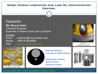
- 1. Diesel Engine Lubrication And Lube Oil Contamination Control Prepared By Md. Moynul Islam Chemical Engineer Expertise on Marine Fuels and Lubricants Contact Email : engineer@moynulislam.com Mobile : +8801816449869 Web : www.moynulislam.com Last Modified On: February 05, 2015A downloadable “pdf “ version is available on author’s website
- 2. Diesel Engine Lubrication And Lube Oil Contamination Control Identify contamination Identify wear and its possible sources Deploy appropriate contamination control guards Move your maintenance practices toward a more condition-based-approach
- 3. Introduction Lubricating oil is imperative for the correct function of an engine. It forms a separating oil film between adjacent moving parts to prevent their direct contact, decrease friction-induced heat and reduce wear. Therefore it protects the engine. One of the most important characteristics of lubricating oil is its viscosity. This has to be high enough to maintain the lubricating oil film and low enough to enable the flow of oil around the engine. During engine operation the characteristics of the oil change. Soot particles generated in the combustion process, contaminate the oil along with small metallic particles caused by mechanical abrasion. These contaminants increase the viscosity of the oil and as a result the oil can no longer completely carry out its protective function. This leads to increased fuel consumption, a loss of engine performance and increased wear or damage to engine components. In order to exclude these risks, the lubricating oil has to be effectively treated. The focus of the treatment is the maintenance of the oil quality and protection of the engine which are two equally important requirements.
- 4. Friction and Purpose of Lubrication To understand lubrication you have to understand friction and also about following things. how friction causes damage How operating conditions can increase damage How lubricants help to prevent damage Reducing friction between moving parts is critical to increasing vehicle/equipment life. Purpose of Lubrication: Protect critical components Provide reliable operation Lower maintenance costs Decrease downtime Increase equipment life Main Functions of Lubricants: Reduces friction in engines Controls friction in transmissions Acts as a heat transfer agent Inhibits corrosion and oxidation Removes contaminants Lessens the effect of temperature extremes on viscosity Noise Reduction
- 5. Engine Parts Lubrication and Engine Oils Functions of Engine Oils Provision of stable oil film between moving surfaces Provision of reliable engine operation in a wide temperature range Rust / Corrosion protection in engine components Cleaning the engine components from sludge Sealing Piston Ring- Cylinder Gap Prevention of Foaming Cooling the Engine Parts Piston Motion in Cylinder Crankshaft Rotation in Engine Bearings (Main Bearings and Big End Bearings) Piston Pin Rotation in the Bush of Small End of the Connecting Rod Camshaft Rotation in Camshaft Bearings Cams Sliding Over the Valves Rods Intermediate Gears Turbocharger Bearings Pedestal Bearing Reciprocating Motion of Valve Stems Engine Parts Lubricated by Engine Oils
- 6. Functions of Engine Oil Provision of stable oil film between moving surfaces It prevents direct metal to metal contact by creating a continuous oil film (hydrodynamic lubrication regime functions as a hydraulic lifters) between two moving surfaces like rotation of crank shaft and engine bearings, reciprocating motion of piston rings over cylinder liner inner wall, various gears arrangements, etc. It reduces the coefficient of friction as the oil film keeps moving surfaces away from each other and that ease the movements of moving parts producing less heat. It helps to evenly distribute load applied bearing over its surface, cools down the sliding parts. It takes foreign particles away from the friction region Provision of reliable engine operation in a wide temperature range Viscosity of oils strongly depends on its temperature. Again the oil film thickness depends on oil viscosity. When an engine starts at low temperature the oil is viscous (Thick). If the viscosity is too high the oil will not be able to flow to the sliding parts and the non-lubricated engine will not run. On the other hand oil viscosity in an heated engine is low. The oil flows easily, however the oil film thickness of hot oil is low, and it may become less than the roughness of the sliding surfaces. In this case hydrodynamic lubrication regime is broken and direct metal to metal contact between the surfaces occurs. Metal to metal contact causes excessive wear, overheating and even fatigue of the sliding surfaces. Hence, lubrication is formulated considering the requirement in both cases.
- 7. Functions of Engine Oil >> Rust / Corrosion protection in engine components Combustion gases containing water vapors and other chemically active gases partially penetrate to the crankcase and may cause corrosion. In addition to this some constituents of combustion gases dissolve in the oil and increase acidity. Such oil may become aggressive to the metal parts contacting with it. Corrosion inhibitors are added to engine oils in order to provide protection of metallic (both ferrous and non-ferrous) parts. >> Cleaning the engine components from sludge Combustion gases past through the piston rings to the crankcase contain some amount of not burnt carbon which may deposit on the rings, valves and cylinders, forming sludge. The sludge clogs oil passages and clearances decreasing lubrication of the engine parts. In order to remove the sludge from the surface, detergents are added to the engine oils. Dispersants, which are also added to the engine oils, help to maintain maintained removed sludge and other contaminants (both ferrous and non-ferrous) in form of fine suspension permitting engine functioning between the oil changes. >> Sealing Piston Ring- Cylinder Gap Imperfection on the surfaces of the piston rings and cylinders walls result in penetration of combustion gases in to the crankcase, which decreases the engine efficiency and cause contamination of the oil. Engine oil fills these microscopic passages and seal the ingression of combustion gases.
- 8. Functions of Engine Oil >> Prevention of Foaming Engine oil circulating in an engine may entrap air and form foams. Foamed oils are less effective in their important functions (oil film formation, heat removal, cleaning). In order to diminish foam formation special additives anti-foaming agents are added to the engine oils. >> Cooling the Engine Parts Combustion heat and friction energy must be removed from the engine in order to prevent its overheating. Most of heat energy is taken by the engine oil. Clean oil passages, proper viscosity and low contamination provide sufficient flow rate of the engine oil and effective cooling.
- 9. Surface Roughness, Friction and Lubrication To understand the working principle of lubricants, first of all you have to be familiar with the nature of the two surfaces to be lubricated. Whenever a surface is machined (no matter how sophisticated tools are being used) there will be tiny microscopic irregularities in the machined surface. The nature of these irregularities will vary depending upon the materials, machining process (i.e. rolling, turning, grinding, milling or plateau honing, lapping, but the net effect is the same. Under microscopic examination, the surface is anything but smooth. When two such surfaces are forced to slide over each other, opposing high spots (known as asperities) will contact, resisting any sliding motion. The contact invariably alters the surface of the mating parts due to distortion, scuffing, micro-welding and subsequent tearing. An engine or any machine operated under such conditions would not last long without corrective maintenance Figure: Surface roughness in different machining operation
- 10. Surface Roughness, Friction and Lubrication Figure: Microstructure of polished liner surfaceFigure: Polished (by honing) liner surface Visual Appearance of cylinder liner surface Microscopic Appearance of cylinder liner surface
- 11. Surface Roughness, Friction and Lubrication Video Clip To Illustrate Friction and Lubrication
- 12. Types of Metal Contacts Rolling contact takes place in ball and roller bearings and in gear drives. As shown in figure , large compressive forces act between the component surfaces. The lubricant is swept into the contact zone by the rolling motion. Particles larger than the thickness of the lubricant film separating the opposing surfaces indent and pit the surfaces. Figure: Schematic Diagram of Rolling Contact There are three types of relative motion which can take place between diesel engine component surfaces. >> Rolling Contact >> Sliding Contact >> Squeeze Contact
- 13. Sliding Contact Sliding Contact takes place in journal bearings and ring-cylinder contacts. During sliding contact the lubricant is swept into the contact zone by the relative motion of the two surfaces. The presence of particles larger than the dynamic film thickness leads to severe abrasive wear. Hard particles cut away material from the component surfaces, with the simultaneous generation and release of new contaminant particles into the fluid.
- 14. Squeeze Contact Squeeze Contact takes place because of linear forces and vibration. The valve-to-cam follower contact is a good example. In squeeze contact, motion perpendicular to the opposing surfaces forcing lubricant in and out of the contact zone. Particles caught between the surfaces will roughen and dent the components. This leads to abrasive removal of material, fretting, and fatigue.
- 15. Dynamic Clearances and Critical Film Thickness In lubricated contacts, dynamic clearances are maintained by oil films between moving surfaces. The lubricant film thickness, as shown in Figure , is the distance between the two moving surfaces. Compressive forces (the load) act to push the moving surfaces together. Tangential forces (shear) tend to displace the surfaces horizontally. A film of oil supports the load between the opposing surfaces and keeps them separated. The thickness of the oil film is related to the mode of lubrication that we will discuss in subsequent slides.
- 16. Particle Size Distribution in Used Diesel Engine Oil Figure: Particle Size Distribution in Used Engine Oil Based on above figure, more than 99% of these particles are less than 20 micron in size
- 17. ISO 4406:1999 Cleanliness Rating Number What is the meaning of “micron” in particle size? Below figure can help your perception about micron size The cleanliness rating of engine oils is measured via the lube oil particle count. Most particle counter reports results at six particle diameter size ranges: 4µ, 6µ, 14µ, 21µ, 38µ and 70µm. An ISO Cleanliness rating number is derived from the results of three smallest sizes, therefore the minimum particle count test should furnish results at 4µ, 6µ, 14µm. Before discussing about particle size we need to refocus our perception about micron size.
- 18. ISO 4406:1999 Cleanliness Rating Number What Actually The Code Represents?
- 19. Chain Reaction of Wear Breaking The Chain Reaction Of Wear: In a study by Dr. E. Rabiniwicz of M.I.T., the observation was made that 70% of component replacements or "loss of usefulness" is due to surface degradation. In hydraulic and lubricating systems, 20% of these replacements result from corrosion, with 50% resulting from mechanical wear. Particles generated as a result of abrasive wear are work hardened; thus they become harder than the parent surface. If these particles are not removed by proper filtration, they will recirculate and cause additional wear. This "chain reaction of wear" will continue and result in premature system component failure unless high-performance filtration is applied to break the chain. 92U235 + 0n1 → 3 0n1 + 36Kr92 + 56Ba141 + ENERGY Uncontrolled Fission Chain Reaction Controlled Fission Chain Reaction Most reactors are controlled by means of control rods that are made of a strongly neutron-absorbent material such as boron or cadmium
- 20. Lubrication Methods Types of Lubrication Methods Boundary Lubrication Hydrodynamic Lubrication Elastohydrodynamic Lubrication Engine Parts Lubricated By Engine Oils Piston Motion in Cylinder Crankshaft Rotation in Engine Bearings (Main Bearings and Big End Bearings) Piston Pin Rotation in the Bush of Small End of the Connecting Rod Camshaft Rotation in Camshaft Bearings Cams Sliding Over the Valves Rods Intermediate Gears Turbocharger Bearings Pedestal Bearing Reciprocating Motion of Valve Stems
- 21. Coefficient of Friction and Types of Lubrication The relationship between friction, pressure, speed and lubrication is expressed as the coefficient of friction. The coefficient of friction is found by dividing the force required to move a body over a horizontal surface at constant speed by the force holding the body against the surface. Coefficient of Friction (F) = Lubricant Viscosity (Z) x Speed (N)/ Perpendicular Load (P) Against Surface The lubricant viscosity is a measure of its resistance to flow. As the number of asperities on the surface increases the coefficient of friction increases. Higher the coefficient of friction means more force is required to move parts over another surface because of the increase in frictional drag force. The additional power required to overcome this frictional drag is wasted resulting an inefficient operation and wastage of additional energy. Excessive friction increases heat, wear and component damage depending on the severity of operating conditions. Streibeck Curve shows the effects of viscosity, speed and load on friction.
- 22. Fluid Film or Hydrodynamic Lubrication Under conditions of fluid film or hydrodynamic lubrication the oil is swept into the contact zone by the relative motion of opposing surfaces. The lubricant film, usually larger than 2 microns, develops up to 50,000 psi pressure in the contact zone. This pressurized film supports the load between component surfaces. There is little or no deformation of the component surfaces in the contact zone. Studies show that wear rates and particle generation are less when the ratio of film thickness to surface roughness (average height of asperities) is greater than three to one. Under these circumstances, mechanical surface wear is negligible unless solid particles the size of or larger than the oil film thickness are present.
- 23. Boundary Lubrication Figure, illustrates the conditions that exist during boundary lubrication. Low speeds, high loads, and squeeze contact between component surfaces can starve ,the contact zone of lubricant. In addition, start up, shutdown, and high temperature thinning of the oil are duty cycle conditions that can lead to oil starvation. The remaining lubricant film between the surfaces is 0.001 to 0.05 microns thick. High stress or heat at the asperity contact sites may displace this boundary layer of lubricant, leading to adhesive wear. Because of the extremely thin film, very fine particles can cause surface damage. It is important to note that a component can shift between the three modes of lubrication several times during a single duty cycle. The EP additive is active under heat and pressure. This EP additive reacts with metal surfaces to form a protective film. This film coats the microscopic peaks on the interacting surfaces. This film has low shear strength but high solid to liquid transition temperature. It acts as a sacrificial wear layer reducing friction between interacting components and protecting them from excessive wear.
- 24. Elastohydrodynamic or EHD Lubrication Under conditions of elastohydrodynamic lubrication the oil is swept into a highly loaded concentrated contact where lubricating film thickness varies between 0.05 and 2 microns. In the contact zone there is considerable elastic deformation of the surfaces. The fluid film at the contact zone develops as much as 350,000 psi pressure. This extreme pressure greatly increases the viscosity of the oil within the contact zone. The high pressure in the contact zone causes solid particles the size of or larger than the lubricant film to indent or furrow deeply into the component surface. Two things happen in EHD lubrication; first the surfaces in contacting parts deformed elastically spreading the load over a wide area; second the viscosity of lubricant in this area momentarily increases dramatically increasing its load carrying ability in the contact zone. The combined effect is to trap a thin but very dense oil film between interacting surfaces. As viscosity increases, sufficient hydrodynamic force is generated to form a full fluid film and separate the surfaces.
- 25. Different Lubrication Regimes Video Clip To Illustrate Different Lubrication Regimes
- 26. Types of Contaminants Lubricant contaminants degrade the life and performance of diesel engines. These contaminants fall into three categories: 1. Solid particles, including wear debris, which damage mechanical components and catalyze lubricant breakdown. 2. Liquid contaminants, including fuel and water, which hinder the proper operation of the lubricant and its additives. 3. Gaseous contaminants, including combustion products, which corrode component surfaces and break down the oil. The predominant types of diesel engine oil contaminants, along with primary sources and major problems these impurities cause, are listed in next slide
- 27. Contamination of Diesel Lube Oil
- 28. How Contaminants Enter in Lubricant? Contamination enters the engine lube system by four routes: 1 ) built-in from manufacture and assembly, 2) Maintenance Activities 3) External Ingression, and 4) Internal Generation Built-in Contamination: Diesel engine manufacturers take great care during the manufacture and assembly processes to ensure high quality control. However, casting materials, machining swarf, abrasives, polishing compounds, and even lint remain after manufacture and overhaul. These built-in contaminants can rapidly damage moving engine parts. Maintenance Activities: During maintenance activities contaminants are introduced into the lubrication system. Opening rocker covers, the engine head, even the oil filler cap allows entrance of dust and water. Simply making and breaking a fitting generates tens of thousands of damaging particles. In addition, new oil contains contaminant particles
- 29. Ingression of Lubricant Contaminants External Ingression: External ingression is a major source of hard particle contamination. Airborne particles, in the form of sand, salt, and other minerals, enter through the engine intake system and mix with the atomized fuel, which is compressed and then burned. Since most of these particles have melting points considerably above the temperatures reached in the diesel combustion process, they remain hard abrasive solids. Air-borne contamination has been shown to be the greatest cause of ring-to-cylinder wear . The strong pressure shock wave created during combustion forces gases through the piston ring clearances. This process, known as blowby, carries particles into the engine oil. Particles may also be retained in the oil film. They are then wiped by the rings into the oil sump on the next down stroke of the piston. Exhaust gases are similarly driven into the lube oil as blowby gases. These exhaust gases include unburned fuel, water, nitrous oxide, soot, and other partially burned hydrocarbons. Other paths for external ingression of contaminants into the engine oil include crankcase breathers, which can admit large quantities of dust and water directly into the oil sump, and diesel fuels contaminated with particles. In addition, water combined with anti-freeze compounds such as glycol can be forced into the oil cavity under pressure through defective head gaskets, or, occasionally, through a crack in the block.
- 30. Ingression of Lubricant Contaminants Internal Generation: Internal generation of contaminants is by wear of mechanical component parts and by lubricant breakdown. Mechanical component wear from abrasion, fatigue, adhesion, and corrosion releases harmful particles into the oil. The wear debris is in the form of hard metal particles and of abrasive metal oxides. Wear debris particles of sizes not controlled by standard filtration can build up to grossly contaminate the lube oil. Lubricant breakdown is the loss of important properties of the oil plus accumulation of harmful materials derived from the oil. These materials include acids, sludges, gels, and additive precipitates. These contaminants can wear moving component parts as well as clog flow passages and heat exchange surfaces. If wear debris and materials from lubricant breakdown accumulate in the oil, the result is more wear, generating more contaminants. The process of particles wearing surfaces and generating new particles that in turn cause more wear is known as the chain-reaction-of-wear.
- 31. Contaminant Particle Size and Engine Component Wear There is an important relationship between the size of contaminant particles and the thickness of dynamic lubricant films separating opposing surfaces. Particles the size of and larger than the lubricant film thickness cause wear of component surfaces. These particles bridge the gap maintained by the oil film, making simultaneous contact with both surfaces. This focuses the force between the surfaces, causing damage and resulting in component wear. An extensive survey of the technical literature for oil film thicknesses in diesel engine components is summarized in Table 2. Most of these dynamic clearances are between 0 and 20 microns. Contaminant particles the size of or larger than these dynamic clearances produce a major portion of the wear experienced by diesel engine oil wetted components. Based on above data, particle size 0 – 10 micron are more damaging than larger particles.
- 32. Mechanism of Wear There are five forms of wear that occur in diesel engine components: abrasion, fatigue, adhesion, corrosion, and lubricant breakdown. Abrasion, fatigue, and adhesion involve mechanical damaging of surfaces; corrosion and lubricant breakdown involve chemical reactions. Abrasion: Abrasive wear by contaminant particles involves the rapid cutting away of component material an abrasive particle abutting one surface slides along and ploughs through the opposing surface. Material is cut away in a single pass. The rate of abrasive wear is proportional to the number of contaminant particles the size of or larger than the dynamic lubricant film. The results of abrasive wear are: roughened surfaces, loss of clearance, misalignment, and generation of fresh wear debris. Particles generated from this process are similar to microscopic machine chips. These particles add to the oil contamination and accelerate the chain-reaction-of-wear
- 33. Mechanism of Wear Mechanism of Abrasive Wear: Abrasive wear is the primary wear mechanism. Particles enter the clearance between two moving surfaces, burry themselves in one of the surfaces, and act like cutting tools to remove materials from opposing surface. The size of particles causing the most damage are those equal to and slightly larger than the clearance. Most diesel engine components have dynamic clearances less than 20 micrometers. To protect opposing surfaces from abrasive wear and fatigue, particles of approximately this clearance size range must be removed deploying appropriate equipments.
- 34. Mechanism of Wear Fatigue: Fatigue of a component surface is due to an accumulation of microscopic cracks at or just below the component surface. These cracks accumulate over an operating period, eventually combining to form voids which undermine the surface. Large quantities of material then break away, leaving a cratered surface and releasing work hardened particles into the oil which continue the chain reaction-of-wear. As shown in Figure, by focusing the force between loaded surfaces, particles larger than the lubricant film dent and crack the surfaces. For component surfaces in rolling or squeeze contact, surface fatigue caused by particles may be the primary wear mechanism. Particle is caught Surfaces dented, cracking initiated After fatigue cycles, cracks spread Surface fails, particles released
- 35. Mechanism of Wear Adhesion: Adhesive wear occurs when the boundary layer lubricant film between the asperities of two opposing surfaces is displaced. This is shown in the Figure. Metal-to-metal contact between surfaces can lead to spot welding of these asperities. As the asperities of the moving surfaces part, the microscopic spot welds often break asymmetrically, removing material from the surface with the lower yield strength. The result is high friction, wear, and heat generation. If a large number of spot welds are produced simultaneously, the surfaces can no longer move apart and seizure occurs. Degradation of surfaces by particles, such as roughening and misalignment, can lead to surface-to- surface contact and adhesive wear.
- 36. Mechanism of Wear Corrosion: Corrosion is a reaction between aggressive chemicals and component surfaces. Aggressive chemicals include water, dissolved oxygen, and NOx, SOx from the combustion gases. Two mechanisms by which corrosion degrades surfaces are: 1) the reaction products dissolve in, and are removed by the lubricant, and 2) the reaction products form a brittle crust, often of abrasive metal oxides, which breaks away from the surface. Particles from these corrosion crusts add to the lubricant contamination, accelerating the chain-reaction of- wear. Corrosion is often accelerated on surfaces damaged by contaminant particles. These worn surfaces have cracks that allow corrosive chemicals to penetrate through protective surface films and react with the underlying material Lubricant Breakdown: Lubricant breakdown is the loss of important oil properties, such as viscosity, and the build-up of harmful materials derived from the lubricant. Lubricant breakdown can be caused by several mechanisms. Fuel and water can mix with the lubricating oil to form precipitates and gels. Soot particles, carried into the lubricant with blowby gases along with wiping of the piston-rings, can combine with anti-wear and viscosity additives in the oil to reduce wear tolerances(5) and increase viscosity(6). It has been shown that particles of fresh wear debris have catalytic surfaces that accelerate oil oxidation. Oxidation of the oil leads to varnishes, sludges, and increased oil acidity.
- 37. Diesel Engine Component Wear Piston Rings/Cylinder Wear: The piston-rings have a reciprocal sliding motion. The outside of most piston-rings is rounded and chrome-plated to produce the best oil film thickness and wear resistance. As the pistons start to move in the cylinders, a hydrodynamic oil film is formed between the ring and cylinder surfaces which helps to prevent wear
- 38. Diesel Engine Component Wear Piston Rings/Cylinder Wear (Cont’d): When there is little or no relative motion between the rings and the cylinder (e.g. prior to start and at TDC and BDC), the fluid film is thin. This is when wear will most likely occur, since the oil is being squeezed from the contact area. When the piston reaches the bottom of its travel, the walls of the cylinder are completely exposed to the high temperatures and products of combustion, as well as to contaminant particles ingressed with the air and fuel. The thin layer of lube oil left by the previous pass of the piston may also become partially oxidized. Deposits formed are either expelled in the exhaust on the upstroke or are swept into the oil sump by the piston rings on the downstroke. When the piston reaches the top of its stroke, new oil is splashed or sprayed onto the walls of the cylinders washing a portion of the previously contaminated oil film into the sump. If the combustion by-products and particulate contamination drawn in with the air and fuel bridge the oil film between the ring and cylinder, wear occurs. Wear particles can also be supplied to the contact areas by contaminants already present in the oil. The major sources of these contaminants are prior blowby, lubricant breakdown, and component wear. Particles generated by wear between piston-ring and cylinder range up to 30 microns in size and are work-hardened. These particles are abrasive to other engine components as well as to the rings and cylinders
- 39. Diesel Engine Component Wear Piston Skirt/Cylinder Wear: Contact between the piston skirt and the cylinder or liner is often overlooked as a form of wear. Scuffing can occur between these two parts during cold starts and other severe operating conditions. Particles generated by this type of contact are quite abrasive as a result of work hardening and can range in size from silt to 60 microns and larger. These metal particles contribute to the chain reaction-of-wear, causing extensive damage if not controlled
- 40. Diesel Engine Component Wear Plain Bearings: Plain bearings are used to support the cam and main drive shafts and to transmit the power delivered to the drive shaft by the piston and rods. Average oil film thicknesses are approximately 4-5 microns.
- 41. Diesel Engine Component Wear Plain Bearing Wear: Plain bearings are also used on many accessories, such as turbochargers and oil pumps. Another form of plain bearing is the thrust bearing used in turbo-chargers. This sliding contact bearing absorbs the high axial loads generated by the turbocharger compressors. Most plain bearings have a soft running surface applied by the manufacturer to absorb particulate contamination while supplying a good cold start self-lubricating surface. Because of their softness, these surfaces depend on the lube oil film thickness to prevent wear. Hard contaminant particles can embed in the soft liner of the bearing If securely embedded in the bearing and large enough to bridge the oil film thickness between surfaces, this hard particle contamination causes wear of the journal. If the particles are larger than the oil film thickness but are not securely embedded in the soft bearing surface, they can score both the bearing and journal by a tumbling abrasive action. As shown in Slide XXX, test data indicate that a majority of wear on diesel engine plain bearings is caused by particles 10 microns and smaller.
- 42. Diesel Engine Component Wear Wear in Valve Train: The valve train functions to open and close the intake and exhaust ports to the combustion area at a specified time. The rotational sliding speed and high lifting loads between the cam lobes and follower cause lubrication problems. In many diesel engines, this cam-to-follower interface receives the heaviest wear because of low oil film thicknesses. Extremely small particles circulating in the lube oil can bridge the space between the surfaces and cause wear. Location of the valve train at the top of the engine also generates extensive carbon deposits due to heat. These carbon deposits have been shown to adversely affect the anti-wear additives in the oil. Stiction of the valve in the valve guide can lead to extensive power loss. Stiction is produced by carbon deposits and hard particles lodged between the valve and guide. This causes the timing of the port openings and closings to vary, causing incomplete combustion in the cylinder as well as combustion in the exhaust manifold (backfiring). Even if stiction is temporary, permanent power loss can result from a burnt valve seat. Rocker arms and followers are often supported by plain bearings. These bearings are lightly loaded and have restricted movement. However, high temperatures and poor lubrication produce small lubricant film thickness and lead to severe abrasive wear problems (scoring). Under cold start conditions, the lube oil can take several minutes to reach these rocker arm bearings, further reducing film thickness.
- 43. Diesel Engine Component Wear Wear in Accessory Drives: Many diesel engine accessories are gear driven. These gears shift from sliding to rolling contact and back to sliding contact as the teeth mesh and then separate. While driving relatively light loads, the contact area of these gears is quite small so contact pressure is high. With lubricant contamination larger than one micron, scoring abrasive wear occurs in the sliding contact areas and fatigue and abrasive wear occur under rolling contact. Oil pumps are also subject to wear between the housing and sides of the gears, which have a circular sliding friction contact with a typical clearance of approximately twenty-five microns
- 44. Key Parameters Strongly Related with Engine Health Viscosity: The lubricant viscosity is a measure of its resistance to flow. As the number of asperities on the surface increases the coefficient of friction increases. Higher the coefficient of friction means more force is required to move parts over another surface because of the increase in frictional drag force. The additional power required to overcome this frictional drag is wasted resulting an inefficient operation and wastage of additional energy. Excessive friction increases heat, wear and component damage, lubricant breakdown depending on the severity of operating conditions,
- 45. Key Parameters Strongly Related with Engine Health Total Base Number - TBN: This TBN is only relevant to diesel engine lubricants. It is not relevant for gear oils or hydraulic oils. Alkaline additives are present to neutralize acids derived from both combustion (mainly strong Sulphuric and Nitric acids) and those weaker, organic acids resulting from oxidation of the oil as occurs during ageing. TBN is a measurement of the capacity of engine oil for neutralizing strong acids from combustion of fuel oil. It is not a measure of how alkaline an oil is (the alkalinity is more akin to soapiness than strong alkali) but it instead measures the alkaline reserve of the oil or its ability to neutralize acids. The TBN of trunk piston diesel engines (high and medium speed) will fall due to exposure to combustion products but generally reaches a stable level as consumption of TBN by neutralization is matched with replenishment by fresh oil top-up. TBN of system oils in large 2 stroke cross head type engines may rise due to contamination of the oil with very high TBN cylinder oil draining, via the stuffing boxes or from top-up with incorrect oil grades. A drop of around 50% of fresh oil TBN indicates that the oil is almost at the end of its useful life. Another useful indicator is a minimum TBN equal to 7 times the sulphur content of the fuel in use. Oil suppliers usually recommend a change or partial replacement at this level in order to optimize the acid neutralizing properties of the oil. This recommendation is mostly based on engine manufacturer’s advice. Low TBN reserves provide insufficient neutralization capacity leading to corrosion of engine components particularly around the piston ring pack, piston ring lands and top end bearing. Fouling of the engine internals and under piston cooling ways may also increase.
- 46. Key Parameters Strongly Related with Engine Health Total Base Number – TBN (Continued): TBN in gas-fuelled engines is often achieved using a very low ash additive pack. Additives are often based on automotive practice using magnesium in preference to calcium salts. Low ash properties are specified, as hot ash on combustion components can result in pre-ignition of the gas during the induction or compression strokes. TBN in these applications can fall very rapidly due to high operating temperatures and, if using land fill gas, contaminants in the fuel itself. Causes of rapid TBN depletion Low oil consumption Small sump volumes High fuel sulphur levels Another silent reason for rapid TBN depletion is excessive lube oil contamination especially by Soot and Wear Debris. These two contaminants acts as a catalyst to break down the lubricant in the presence of elevated temperature and high pressure and produces various organic acids which are also responsible for rapid TBN depletion. Hence, efficient removal of contaminants from lube oil will definitely increase oil service hours, minimizes lube oil consumption and ensure better protection to engine components.
- 47. Key Parameters Strongly Related with Engine Health Abrasives – Soot/Wear Metals/Dirt: Soot, sub-micron sized particles produced from incomplete combustion of fuels in diesel engines. How Soot(a sub-micron sized particle)/Wear Metals/Dirt Particles Affect Your Engine Performance 1. They act as a catalyst to breakdown lube oil followed by destroying the effectiveness of lubricating oil 2. They Actively Participates in Rapid Filter Clogging 3. They Reduces Oil Service Life and Indirectly Equipment Service Life. 4. They Play an Active Role in TBN Depletion. 5. Existing MDC Type Lube Oil Separators are quite inefficient to remove soot (a sub-micron sized particle) and other particles sized below 5 microns. But Pressure Powered Centrifugal Oil Filters are very effective in removing such types of sub-micron sized particles. In subsequent slides we will discuss in detail about the performance of different fluid filtration system.
- 48. Lube Oil System in Large Diesel Engine Lube Oil Separator Unit Full Flow Filters Engine Driven LO Pump Electric Driven LO Pump HP Relief Valve Lube Oil Cooler
- 49. Full flow filters Full Flow Filtration Full flow filters are the most common type, and receive all, or nearly all the oil pumped around the engine. They provide essential engine protection for maximum cold flow performance and filter life. Full flow filters need to be able to provide good filtration, handle the required flow rate even when the oil is cold, and provide adequate dirt holding capacity. The use of synthetic media or cellulose media filters are very common. By-pass (secondary) Filtration Sometimes referred to as a secondary filter, a by-pass filter is usually fitted to a separate line where a small portion, usually of about 5 – 10% of the total oil flow, passes through them and is then diverted back to the sump. A bypass filter is usually a much finer filter to capture smaller particles than the full flow. Because it has a higher efficiency, it will have a much lower flow rate than a full flow filter; especially when the oil is cold. It is designed to improve the overall cleanliness of the oil without compromising the flow rate to the engine. Two-stage Filtration A two-stage filter design attempts to combine the features of both a full flow and a by-pass filter. The two-in-one design significantly increases restriction, causing shorter filter life and decreased cold flow performance. Poor cold flow performance starves the engine of oil during start up, leaving the engine temporarily unprotected. This will lead to increased engine wear that may result in premature repairs or even engine replacement.
- 50. Lube Oil System in Diesel Engine Lube Oil Separator Unit SEPARATORINLET SEPARATOROUTLET SLUDGE
- 51. Typical Full Flow Filter Elements Stainless steel wire mesh, wedge wire profiles Filtration Grades: 3 µm - 50 µm, Paper, Polyester, Fiber glass made disposable cartridge used for flushing liquid treatment
- 52. Reverse Flush Self Cleaning Filter (RFSCF) (Automatic Filter) Mud Box Filter: Filtration Grades: 3 µm - 50 µm, Paper, Polyester, Fiber glass made disposable cartridge used for flushing liquid treatment Automatic Filter: Filtration Grade: 35 µm , Stainless steel wire mesh, wedge wire profiles Internal Candle ElementsBOLL & KIRCH Filterbau Automatic Filter Mud Box Filter
- 53. Lube Oil Safety Filters (Once Through Duplex Type) Duplex Type Once Through Lube Oil Safety Filter: Filtration Grade: 60 µm , Stainless steel wire mesh, wedge wire profiles Candle Elements for Lube Oil Safety Filter: Filtration Grade: 60 µm , Stainless steel wire mesh, wedge wire profiles
- 54. Expectation on Full Flow Filters •It will permit sufficient flow of Lube Oil to the system •It will ensure pressure drop as minimum as possible •It will ensure removal of suspended particles as maximum as possible to protect engine components •It will provide extended service life followed by minimizing downtime •It will be easily cleanable We have seen various full flow filters present in diesel engines. What we expect from a full flow filters? Based on our expectation, Providing Maximum Removal of Particles with Less Pressure Drop is Two Opposite Constraints for a Full Flow Filters To provide sufficient flow, pressure drop to be as low as possible. So the mesh size must be quite large. Again, to remove contaminants from lube oil as maximum as possible, the mesh size must be as small as possible to protect engine components. Hence both opposing constraints to be optimized. To optimize opposing constraints, some contaminants have to allow through full flow filters. So, introducing a bypass filter/lube oil separator is vital for removal of those particles which are not possible to separate by full flow filters.
- 55. Engine Manufacturer’s Recommendations For Lube Oil System Filters in Internal Lubricating Oil System: For Example WARTSILA 18V46 Engine Lube Oil System As a standard the engine is equipped with a built-on side stream centrifugal filter and starting-up/running-in filter(s) Centrifugal filter: The centrifugal filter in by-pass is used as an indicator filter. • Capacity per filter 3.5 m³/h • Filtering properties down to 1m Starting-up or running-in filter: All engines are provided with a full-flow paper cartridge filter in the oil inlet line to each main bearing. The cartridge is used only during running-in and at the first starting- up of the installation Is your engine equipped with Centrifugal Filter?
- 56. Engine Manufacturer’s Recommendations For Lube Oil System Filters in External Lubricating Oil System: For Example WARTSILA 18V46 Engine Lube Oil System Suction strainer >> Fineness 0.5 - 2.0 mm Automatic filter An automatic self-cleaning filter must be installed. Design data: Lubricating oil viscosity : SAE 40 Operating pressure : max. 8 bar Test pressure : min. 12 bar Operating temperature : max. 100°C Fineness 90% separation : above 20 micron) (absolute mesh width : max. 35 micron) Max. permitted pressure drop for normal filters: – clean filter : 0.3 bar – alarm : 0.8 bar Automatic Filter: Filtration Grade: 35 µm , Stainless steel wire mesh, wedge wire profiles
- 57. Engine Manufacturer’s Recommendations For Lube Oil System Lubricating oil safety filter The lubricating oil safety filter is a duplex filter with steelnet filter elements. Design data: Lubricating oil viscosity : SAE40 Operating pressure :max. 8 bar Test pressure : min. 12 bar Operating temperature : max. 100°C Fineness 90% separation above 50 m at once through flow (absolute mesh width max. 60 m) Max. permitted pressure drop for normal filters: – clean filter 0.3 bar – alarm 0.8 bar Duplex Type Once Through Lube Oil Safety Filter: Filtration Grade: 60 µm , Stainless steel wire mesh, wedge wire profiles Candle Elements for Lube Oil Safety Filter: Filtration Grade: 60 µm , Stainless steel wire mesh, wedge wire profiles
- 58. Engine Manufacturer’s Recommendations For Lube Oil System Lube Oil Separator Lube Oil Separator The separator should be dimensioned for continuous centrifuging. Each lubricating oil system should have a separator of its own. Design data: Lubricating oil viscosity : SAE 40 Lubricating oil density : 880 kg/m3 Centrifuging temperature : 90 - 95°C The following rule, based on a separation time of 23 h/day, can be used for estimating the nominal capacity of the separator:
- 59. What is Centrifuge Turn Rate? Separator Turn Rate is the ratio of total hourly centrifuge flow rate divided by total engine lube Turn Rate TR = Total Hourly Flow Rate / Total Sump Oil Volume For an example the Turn Rate of a Pressure Powered Centrifuge: Engine : Cat D399 Engine Speed : 1200 rpm Lube Pump Flow : 163 gpm Crankcase & Accessory Capacity : 135 gallons Centrifuge Flowrate : 8 gpm Turn Rate : 3.5 turns per hour For an example the Turn Rate of a Motor Driven Centrifuge: Engine : WARTSILA 18V46 Engine Speed : 500 rpm Engine Output : 16.3 MW Lube Pump Flow : 289 m3/h Crankcase & Accessory Capacity : 14.0 m3 Centrifuge Hourly Flow Rate : 4.763 m3/h Turn Rate : 0.34 turns per hour
- 60. Filter Ratings Beta Ratio (ß) How Many Particles of a Given Size Will Pass Through the Filter? Actual Filter Efficiency 2 1 out of every 2 particles 50% 10 1 out of every 10 particles 90% 20 1 out of every 20 particles 95% 75 1 out of every 75 particles 98.67% 100 1 out of every 100 particles 99% 200 1 out of every 200 particles 99.5% 1000 1 out of every 1000 particles 99.9% 2000 1 out of every 2000 particles 99.95% The efficiency of a liquid filter on a given particle size is frequently described as either a Beta ratio (ß), or as a percentage (%). Both the Beta ratio and percentages of efficiency compare the amount of contamination before and after the filter. The table below provides the efficiency percentages of the commonly used Beta Ratios. Generally, efficiencies are not provided for micron ratings or particle sizes smaller than 3 micron. When looking at the different fuel filters, it is important to compare apples with apples when considering filtration performance.
- 61. PART 2 CONTAMINATION CONTROL GUARDS IN DIESEL ENGINES This Part in Under Construction