SlideShare une entreprise Scribd logo
1  sur  11
Télécharger pour lire hors ligne
WHEELS
                                  INTRODUCTION

                                  Wheels are most critical part of rolling stock. Utmost care
                                  is taken right from the manufacture to its last use on the
                                  trains. Wheels are most stressed components of railway
                                  vehicles. They carry axle load of up to 25 tonnes and more.
                                  They guide the train on the tracks through curves and
                                  switches and are subjected to constant wear process.

                                      Different functional parts of the wheel (as shown in Fig 1
                                      below) such as flange (4), rim (3), centre (2) or hub (1)
fulfill different task and have therefore different material
properties. Railway wheel is high safety part and special
attention is given during production process of wheel to
the reliability, availability, and safety of the product.

Railway wheels are usually made of unalloyed or low
alloyed steels with a high degree of purity. Tight tolerances
for the single alloying elements are desired in order to
assure a low variation of material properties from heat to
heat.

 European standard EN 13262 defines four different steel grades which mainly consist of up
to 0.6wt% of carbon, up to 0.8 wt% of manganese and up to 0.4wt% silicon. National and
international standards such as UIC 812-3V, GOST 10791, AAR M107-84, EN 13262 define
the wheel steel grades and partly their manufacturing.


                                                                                         Page 1
MANUFACTURING PROCESS

     STEEL MAKING PROCESS
        Steel for the production of railway wheels is
        melted in the electric furnace at 3200deg F with
        the charge of 250 tonnes and tapping in two
        ladles. High quality characteristic of steel is
        provided by the subsequent processing at the
        out of furnace complex of steel treatment. The
        ladles with metal are delivered in turn to the
        unit furnace-ladle, where the metal finishing
        and refining takes place. Steel blowing in the
        ladle by argon along with the refining process
        provide for the sculpture content in the finished metal equal to 0.010% phosphorus –
        0.015% and less, and uniform distribution of another elements. Degassing process is
        affected by means of removing the hydrogen, nitrogen, oxygen dissolved in metal at the
        vacuum degassing set simultaneously with argon blowing. Hydrogen content in steel is
        within the limits up to 2 ppm.
     WHEEL MANUFACTURING
        From electric furnace molten metal is transferred to ladle which pours metal in graphite
        moulds to make ingots. Each ingot is approximately 20 feet long. Ingots are then cut into
        small pieces called billets. Each weight around about 1000 pounds.
        Billets are then transferred to rotary furnace where they are heated to 2400 deg F. From
        other end of furnace machine transfer these billets to scaling unit where their outer
        most layers are removed. After that these billets are subjected to pressure of
        9000tonnes in a press which forge these billets to rough shape of a wheel. The train
        wheel increases 20% in diameter when it rolled on rolling mill. Then it goes to final
        shaping press where centre hole is punched in it. After heat treatment, machine sprays
        cold water to harden the steel. Wheels are machined to correct shape of rim, axle hole
        and imbalance checking. Various Non destructive tests like magnetic particle and
        ultrasonic tests are carried out to check any abnormalities in the wheel. The chemical
        composition of steel is checked by spectrometer. Automated brinell is used for
        measuring hardness.


                                                                                          Page 2
The Technology of the Production of Railway Wheels


  Open-hearth furnace                Ladle                 Ladle-furnace         Vacuum degassing set


 Notching and breaking Billets inspection      Billets heating in   Hydroscaling of   Open forging on the
of ingot into initial billets and repairing   the rotary furnace        cinder           press 20MN


  Closed forging on the      Punching on the press      Wheel rolling on the    Wheel calibration on the
       press 50MN                   100MN                  rolling mill           press 35/8 MN and
                                                                                piercing of central hole


  Intermediate cooling       Cooling of the wheel            Machining                Wheels heating
    and anti-flocking             in open air
    isometric holding


     Rim quenching             Tempering in pit          Adjustable cooling         CNC machining,
                                in the furnaces                                   imbalance checking


    Automated non-           Wheels inspection and     Testing of mechanical             Storage
       destructive           measuring, hardness        and other properties
 control (ultrasonic test,      determination             on the samples
    magnetic particle
     inspection etc.)


                                                                                                   Page 3
MAJOR WHEEL DEFECTS IN RAILWAY INDUSTRY
New designs and modern equipment have culminated in a shift in the mechanisms of
wheel damage over the last 15 years. In 1992 when the last metallurgical survey was
carried out by BR Research, about 80% of wheels were reprofiled due to thermal
damage, largely as a result of inefficient wheel slide protection (WSP) systems. The other
causes of premature wheel turning were identified as wear, including flange wear and
thermal damage caused by wheel slide and tread braking. Today it is estimated that up
to 80% of wheels are reprofiled due to rolling contact fatigue (RCF), and although an
increase in total wheel life has been achieved, improvements are still sought.

The British Standard and European specifications for railway wheels describe classes of
heat treated wheels. The choice of the class of wheel to be used for any particular type
of rolling stock and service is based on the conditions to be met.
WEAR
Wheel life depends largely on the resistance of the wheel to wear and its immunity to
tread failures caused by thermal cracking and shelling as a result of RCF.
Wear of wheels occurs on the wheel tread and flange. This can be minimized by
Correct alignment of the wheels, flange lubrication, material of wheel and rail being
similar and equipment in proper mechanical condition. Every effort should be made to
avoid the abnormal loss of tread metal caused by thermal cracking and shelling. The
most effective form of flange wear reduction is by flange lubrication, which can reduce
wear by at least six times. Where this is cost prohibitive or not practical, wear can be
improved by increasing the carbon content of the steel, and by promoting the
morphology of the pearlite microstructure by altering the quench rate. A typical wear
profile is shown in Figure given below


                              EXAMPLE OF FLANGE WEAR


                                                                                  Page 4
HOLLOW WHEEL OR DEEP FLANGE

While the wheel moves there is constant wear on the tread and thus the diameter of wheels at tread
start reducing. Due to which wheel flange height increases. Deep flange is dangerous because it
starts damaging fish plate, fish plate bolts, distance blocks, points and crossings etc. Moreover
inclination of 1 in 2.5 and 1 in 20 (1in 50 in Dubai Metro trains ) practically vanishes which results in
higher friction and there is every possibility of wheels to derail on curves for two wheels on same
side cannot be suitably converted with different diameters to suit longer outer and shorter inner
rails automatically.


                             HOLLOW WHEEL OR DEEP FLANGE

RADIUS TOO SMALL AT THE ROOT OF FLANGE

Root radius in Dubai Metro trains is R15. In service radius at the root of flange is subjected to
maximum wear on curves and by snaking effect of the wheels. When it is reduced to R13 gauge will
fit properly as shown in fig below.

Defect results in to increased friction between rail and flanges because of reduction in taper of 1 in
2.5 given on wheel flange which affects hauling capacity of the train besides wearing effect on the
rails also.


                 FIGURE SHOWING RADIUS TOO SMALL AT ROOT OF THE FLANGE.

                                                                                                 Page 5
THIN FLANGE

Flanges are subjected too severe side thrusts during the run and as such the strength of the flanges
ought to be adequate to sustain all the severest side thrusts and maintain smooth running. When
they wear thin they become weaker and there are cases when flanges could not sustain side thrusts
and broke causing mid section accidents. Besides thin flanges cut through the partly opened facing
points due to any signal or permanent way or other defect causing two roads under same train and
serious accidents follow thereafter.


THIN WHEEL

Wheels become thinner because of continuous wear and metal removal in wheel reprofiling. Thin
wheels are considered unsafe because it can further be thinned due to hammering impact at rail
joints resulting into cracks and breakages etc.

SHARP FLANGE

Tip of the flange is not square but given the radius R10 and R18. Flange wears sharp when
continuously wheel negotiates curves and during snaking effect of the wheels. When top radius at
the corner towards tread reduces beyond tolerable limit (5mm in IR) is called sharp flange also
known as knife edged flange. It is highly dangerous as it mounts the rails at points and nose and heel
of the switch rails and crossing. It also mounts rail on the curves and easily cause accidents if
happens to negotiate outer rail.


                                                                                              Page 6
WHEEL FLAT

Jamming of brakes or seizure of wheels cause skidding of wheels continuous for some distance thus
damaging tread which wears excessively at the point of contact with rail and becomes flat to certain
length and depth. In such cases wheel starts rolling but with unpleasant noise one like we hear on
rail joints. This defect also irks passengers and add to their discomfort. This cause hot axles, journal
breakage, derailments and skidding if allowed for long. It also cause false flanges on tread which is
highly detrimental to safe running of train

Tread Damage occurs from a number of mechanisms including severe tread braking at high speeds
or high speed slip, caused for example by faulty WSP systems or WSP activity combined with low
adhesion conditions, resulting in a heat input into the wheel tread. This locally heated metal then
quenches rapidly due to the ‘colder’ bulk material of the wheel, which acts a heat sink. This phase is
typically 20-30mm wide and 1mm deep. A typical example is shown in Figure below.

This damage on the wheel tread may develop into larger cracks through rolling contact and thermal
input and must be turned out. Resistance to thermal damage can be improved by lowering the
carbon content of the steel. There are also other tread damage mechanisms such as thermal fatigue,
which is associated with tread braking, but would generally be worn away due to the action of
scraping whilst braking on the tread. Low speed slide can induce local heating below the
transformation temperature and at an increased depth. The temperature is high enough, however,
to overload the wheel due to loss of strength as the temperature increases which leads to
mechanical     damage       of    the     wheel      tread   in   the   form      of    a     ‘flat.


                           WHEEL SLIP /SLIDE DAMAGE ON TREAD

ROLLING CONTACT FATIGUE

Rolling Contact Fatigue is the failure of the wheel tread due to cyclic fatigue. In Britain, there are two
notions of rolling contact fatigue;

a) Generally fatigue of the tread contact area due to high loads leading to shelling of the surface, an
example is shown in Figure1 below. This surface breakdown can be greatly accelerated if abnormal
conditions exist and may occur under relatively light static loads.


                                                                                                  Page 7
b) Curving forces experience by the wheel will also cause rolling contact fatigue of the wheel tread; it
is generally seen off centre of the tread towards the field side. This type of rolling contact fatigue is
generally associated with the low of an axle in a curve and leads to chevron type indications on the
field side of the tread, as shown in Figure2 below. It can occasionally be seen towards the flange root
on some wheels and is attributed to the action of the high wheel in curves.


                FIGURE 1                                             FIGURE 2


Fatigue failures of wheels can be surface induced, where initiation is due to gross plastic
deformation of the wheel close to the running surface. This is normally due to high loading and/or
low material strength, and leads to cracks that grow some millimeters into the wheel before
deviating back to the surface and leading to small sections falling away from the tread. This is a
progression from the initial RCF crack initiation shown in Figure 1 and 2 above. Sub surface fatigue
failures occur below the running surface and initiate on a macroscopic defect, although they can
occur in a virtually defect free material if the stresses are too high. These defects can typically grow
to 30mm below the tread before deviating back to the surface, so larger sections of the tread can
break loose. This type of failure is therefore potentially very serious as can be seen in Figure 3 below.


                                          Figure 3


                                                                                                 Page 8
The following factors are found to be detrimental to wheel fatigue life:

High wheel loads

High impurity levels

Small wheel diameters

Small rail radius

Tensile residual stresses

Other damage mechanisms related to premature wheel tread turning are local tread collapse;
indentation damage, rim face bulging, and tread roll over.

High strength and higher carbon content are required for maximum resistance to shelling. On the
other hand, thermal cracking is minimized by lowering the carbon content. These two causes of
failure, thermal cracking and shelling, call for remedies which are the opposites of each other.

For this reason, it is not possible to precisely specify the appropriate class of wheel for the severity
of service which develops under various conditions. The following five factors have an important
influence on the wheel life:

• Static stress in the wheel treads

• Maximum train speed

• Braking requirements

• Track conditions

• Design and condition of equipment


Bibliography
       Wheel Steel Handbook By Rail Safety and Standards Board
       The Journal of Rail wheel interaction
       KLW Wheelco, Ukraine
       The Book of Railway Engineering By PC Gupta , Carriage and Wagon inspector, HQ N.
        Railway, New Delhi
       European Railway Review


                                                           Prepared By      Nishan Singh
                                                                            Rolling stock Technician
                                                                            Date 30/06/2010


                                                                                                   Page 9
Page 10
Page 11

Contenu connexe

Tendances

Maintenance and Manufacturing of Railways
Maintenance and Manufacturing of RailwaysMaintenance and Manufacturing of Railways
Maintenance and Manufacturing of RailwaysSwapnil Pawar
 
Railway workshop jhansi
Railway workshop jhansiRailway workshop jhansi
Railway workshop jhansiAnkur Savita
 
Indian railways mechanical vocational training report 1 haxxo24 i~i
Indian railways mechanical vocational training report 1 haxxo24 i~iIndian railways mechanical vocational training report 1 haxxo24 i~i
Indian railways mechanical vocational training report 1 haxxo24 i~ihaxxo24
 
Lhb coach documentation
Lhb coach  documentationLhb coach  documentation
Lhb coach documentationTURENDARSAHU
 
G 80. inspection and maintenance of centre buffer couplers ( for workshop sta...
G 80. inspection and maintenance of centre buffer couplers ( for workshop sta...G 80. inspection and maintenance of centre buffer couplers ( for workshop sta...
G 80. inspection and maintenance of centre buffer couplers ( for workshop sta...SrinivasaRao Guduru
 
Indian Railways Training on Coach Care Centre
Indian Railways Training on Coach Care CentreIndian Railways Training on Coach Care Centre
Indian Railways Training on Coach Care CentreRao Khola
 
Air suspension in Railway coaches
Air suspension in Railway coachesAir suspension in Railway coaches
Air suspension in Railway coachesSrinivasaRao Guduru
 
Indian railway report main
Indian railway report mainIndian railway report main
Indian railway report mainVicky Gupta
 
central railway internship report
central railway internship reportcentral railway internship report
central railway internship reportrahul waghmare
 
Railway carriage workshop Ajmer
Railway carriage workshop AjmerRailway carriage workshop Ajmer
Railway carriage workshop AjmerBhupesh Jangid
 
Indian Railways - Rail Wheel Factory Report
Indian Railways - Rail Wheel Factory ReportIndian Railways - Rail Wheel Factory Report
Indian Railways - Rail Wheel Factory ReportSameer Shah
 
A project on buffer
A project on bufferA project on buffer
A project on bufferRitesh Rohan
 
Roller bearing used in railway coaches
Roller bearing used in railway coachesRoller bearing used in railway coaches
Roller bearing used in railway coachessachin deora
 

Tendances (20)

Bogie
BogieBogie
Bogie
 
cbc part1.pptx
cbc part1.pptxcbc part1.pptx
cbc part1.pptx
 
Maintenance and Manufacturing of Railways
Maintenance and Manufacturing of RailwaysMaintenance and Manufacturing of Railways
Maintenance and Manufacturing of Railways
 
Railway workshop jhansi
Railway workshop jhansiRailway workshop jhansi
Railway workshop jhansi
 
Wheel Defects
Wheel DefectsWheel Defects
Wheel Defects
 
Modified Fiat Bogie
Modified Fiat BogieModified Fiat Bogie
Modified Fiat Bogie
 
ICF Bogie
ICF BogieICF Bogie
ICF Bogie
 
Indian railways mechanical vocational training report 1 haxxo24 i~i
Indian railways mechanical vocational training report 1 haxxo24 i~iIndian railways mechanical vocational training report 1 haxxo24 i~i
Indian railways mechanical vocational training report 1 haxxo24 i~i
 
Lhb coach documentation
Lhb coach  documentationLhb coach  documentation
Lhb coach documentation
 
G 80. inspection and maintenance of centre buffer couplers ( for workshop sta...
G 80. inspection and maintenance of centre buffer couplers ( for workshop sta...G 80. inspection and maintenance of centre buffer couplers ( for workshop sta...
G 80. inspection and maintenance of centre buffer couplers ( for workshop sta...
 
Indian Railways Training on Coach Care Centre
Indian Railways Training on Coach Care CentreIndian Railways Training on Coach Care Centre
Indian Railways Training on Coach Care Centre
 
Air suspension in Railway coaches
Air suspension in Railway coachesAir suspension in Railway coaches
Air suspension in Railway coaches
 
Indian railway report main
Indian railway report mainIndian railway report main
Indian railway report main
 
central railway internship report
central railway internship reportcentral railway internship report
central railway internship report
 
Fiat bogie
Fiat bogieFiat bogie
Fiat bogie
 
Railway carriage workshop Ajmer
Railway carriage workshop AjmerRailway carriage workshop Ajmer
Railway carriage workshop Ajmer
 
Indian Railways - Rail Wheel Factory Report
Indian Railways - Rail Wheel Factory ReportIndian Railways - Rail Wheel Factory Report
Indian Railways - Rail Wheel Factory Report
 
A project on buffer
A project on bufferA project on buffer
A project on buffer
 
Maintenace manual for wagons
Maintenace manual for wagonsMaintenace manual for wagons
Maintenace manual for wagons
 
Roller bearing used in railway coaches
Roller bearing used in railway coachesRoller bearing used in railway coaches
Roller bearing used in railway coaches
 

Similaire à Wheel Defects

407647493-Manufacturing-of-Rims.pptx
407647493-Manufacturing-of-Rims.pptx407647493-Manufacturing-of-Rims.pptx
407647493-Manufacturing-of-Rims.pptxHenryTinocoCordova
 
Wringer_roll_Position_control_final(edited)
Wringer_roll_Position_control_final(edited)Wringer_roll_Position_control_final(edited)
Wringer_roll_Position_control_final(edited)SHASHANK KUMAR
 
M.tech ppt presentation engine block
M.tech ppt presentation engine blockM.tech ppt presentation engine block
M.tech ppt presentation engine blockPAVAN RAI
 
walkson-presentation-r1.pdf
walkson-presentation-r1.pdfwalkson-presentation-r1.pdf
walkson-presentation-r1.pdfwalkson1
 
turbine and its construction
turbine and its constructionturbine and its construction
turbine and its constructionMayur Ekhande
 
Advance manufacturing report
Advance manufacturing reportAdvance manufacturing report
Advance manufacturing reportSohailAkbar14
 
Aluminium technologies week 12
Aluminium technologies week 12Aluminium technologies week 12
Aluminium technologies week 12rizuwan96
 
A Review on Optimization of the Process Parameters in Friction Stir Welding o...
A Review on Optimization of the Process Parameters in Friction Stir Welding o...A Review on Optimization of the Process Parameters in Friction Stir Welding o...
A Review on Optimization of the Process Parameters in Friction Stir Welding o...IJAEMSJORNAL
 
Production of sheet steel for refrigerator body
Production of sheet steel for refrigerator bodyProduction of sheet steel for refrigerator body
Production of sheet steel for refrigerator bodyJubair Likhon
 
International Journal of Computational Engineering Research(IJCER)
International Journal of Computational Engineering Research(IJCER)International Journal of Computational Engineering Research(IJCER)
International Journal of Computational Engineering Research(IJCER)ijceronline
 
Manufacturing Processes
Manufacturing ProcessesManufacturing Processes
Manufacturing ProcessesAnsar Mulla
 
Aluminium + Ticp Matrix Composite Parting-Off Wheel-Production
Aluminium + Ticp Matrix Composite Parting-Off Wheel-ProductionAluminium + Ticp Matrix Composite Parting-Off Wheel-Production
Aluminium + Ticp Matrix Composite Parting-Off Wheel-ProductionIOSR Journals
 
IRJET- Experimental Study on the Effect of Axial Loading on Light Gauge Steel...
IRJET- Experimental Study on the Effect of Axial Loading on Light Gauge Steel...IRJET- Experimental Study on the Effect of Axial Loading on Light Gauge Steel...
IRJET- Experimental Study on the Effect of Axial Loading on Light Gauge Steel...IRJET Journal
 
Studies on aluminium silicon eutectic alloy casting and design approach of it...
Studies on aluminium silicon eutectic alloy casting and design approach of it...Studies on aluminium silicon eutectic alloy casting and design approach of it...
Studies on aluminium silicon eutectic alloy casting and design approach of it...IAEME Publication
 
International Journal of Computational Engineering Research(IJCER)
International Journal of Computational Engineering Research(IJCER)International Journal of Computational Engineering Research(IJCER)
International Journal of Computational Engineering Research(IJCER)ijceronline
 

Similaire à Wheel Defects (20)

Final pdf report
Final pdf reportFinal pdf report
Final pdf report
 
407647493-Manufacturing-of-Rims.pptx
407647493-Manufacturing-of-Rims.pptx407647493-Manufacturing-of-Rims.pptx
407647493-Manufacturing-of-Rims.pptx
 
Wringer_roll_Position_control_final(edited)
Wringer_roll_Position_control_final(edited)Wringer_roll_Position_control_final(edited)
Wringer_roll_Position_control_final(edited)
 
M.tech ppt presentation engine block
M.tech ppt presentation engine blockM.tech ppt presentation engine block
M.tech ppt presentation engine block
 
walkson-presentation-r1.pdf
walkson-presentation-r1.pdfwalkson-presentation-r1.pdf
walkson-presentation-r1.pdf
 
mmp.pdf
mmp.pdfmmp.pdf
mmp.pdf
 
turbine and its construction
turbine and its constructionturbine and its construction
turbine and its construction
 
Advance manufacturing report
Advance manufacturing reportAdvance manufacturing report
Advance manufacturing report
 
Aluminium technologies week 12
Aluminium technologies week 12Aluminium technologies week 12
Aluminium technologies week 12
 
Training Report
Training ReportTraining Report
Training Report
 
Report_2
Report_2Report_2
Report_2
 
A Review on Optimization of the Process Parameters in Friction Stir Welding o...
A Review on Optimization of the Process Parameters in Friction Stir Welding o...A Review on Optimization of the Process Parameters in Friction Stir Welding o...
A Review on Optimization of the Process Parameters in Friction Stir Welding o...
 
Production of sheet steel for refrigerator body
Production of sheet steel for refrigerator bodyProduction of sheet steel for refrigerator body
Production of sheet steel for refrigerator body
 
International Journal of Computational Engineering Research(IJCER)
International Journal of Computational Engineering Research(IJCER)International Journal of Computational Engineering Research(IJCER)
International Journal of Computational Engineering Research(IJCER)
 
Manufacturing Processes
Manufacturing ProcessesManufacturing Processes
Manufacturing Processes
 
Reading 1
Reading 1Reading 1
Reading 1
 
Aluminium + Ticp Matrix Composite Parting-Off Wheel-Production
Aluminium + Ticp Matrix Composite Parting-Off Wheel-ProductionAluminium + Ticp Matrix Composite Parting-Off Wheel-Production
Aluminium + Ticp Matrix Composite Parting-Off Wheel-Production
 
IRJET- Experimental Study on the Effect of Axial Loading on Light Gauge Steel...
IRJET- Experimental Study on the Effect of Axial Loading on Light Gauge Steel...IRJET- Experimental Study on the Effect of Axial Loading on Light Gauge Steel...
IRJET- Experimental Study on the Effect of Axial Loading on Light Gauge Steel...
 
Studies on aluminium silicon eutectic alloy casting and design approach of it...
Studies on aluminium silicon eutectic alloy casting and design approach of it...Studies on aluminium silicon eutectic alloy casting and design approach of it...
Studies on aluminium silicon eutectic alloy casting and design approach of it...
 
International Journal of Computational Engineering Research(IJCER)
International Journal of Computational Engineering Research(IJCER)International Journal of Computational Engineering Research(IJCER)
International Journal of Computational Engineering Research(IJCER)
 

Wheel Defects

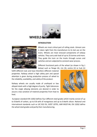
  • 1. WHEELS INTRODUCTION Wheels are most critical part of rolling stock. Utmost care is taken right from the manufacture to its last use on the trains. Wheels are most stressed components of railway vehicles. They carry axle load of up to 25 tonnes and more. They guide the train on the tracks through curves and switches and are subjected to constant wear process. Different functional parts of the wheel (as shown in Fig 1 below) such as flange (4), rim (3), centre (2) or hub (1) fulfill different task and have therefore different material properties. Railway wheel is high safety part and special attention is given during production process of wheel to the reliability, availability, and safety of the product. Railway wheels are usually made of unalloyed or low alloyed steels with a high degree of purity. Tight tolerances for the single alloying elements are desired in order to assure a low variation of material properties from heat to heat. European standard EN 13262 defines four different steel grades which mainly consist of up to 0.6wt% of carbon, up to 0.8 wt% of manganese and up to 0.4wt% silicon. National and international standards such as UIC 812-3V, GOST 10791, AAR M107-84, EN 13262 define the wheel steel grades and partly their manufacturing. Page 1
  • 2. MANUFACTURING PROCESS  STEEL MAKING PROCESS Steel for the production of railway wheels is melted in the electric furnace at 3200deg F with the charge of 250 tonnes and tapping in two ladles. High quality characteristic of steel is provided by the subsequent processing at the out of furnace complex of steel treatment. The ladles with metal are delivered in turn to the unit furnace-ladle, where the metal finishing and refining takes place. Steel blowing in the ladle by argon along with the refining process provide for the sculpture content in the finished metal equal to 0.010% phosphorus – 0.015% and less, and uniform distribution of another elements. Degassing process is affected by means of removing the hydrogen, nitrogen, oxygen dissolved in metal at the vacuum degassing set simultaneously with argon blowing. Hydrogen content in steel is within the limits up to 2 ppm.  WHEEL MANUFACTURING From electric furnace molten metal is transferred to ladle which pours metal in graphite moulds to make ingots. Each ingot is approximately 20 feet long. Ingots are then cut into small pieces called billets. Each weight around about 1000 pounds. Billets are then transferred to rotary furnace where they are heated to 2400 deg F. From other end of furnace machine transfer these billets to scaling unit where their outer most layers are removed. After that these billets are subjected to pressure of 9000tonnes in a press which forge these billets to rough shape of a wheel. The train wheel increases 20% in diameter when it rolled on rolling mill. Then it goes to final shaping press where centre hole is punched in it. After heat treatment, machine sprays cold water to harden the steel. Wheels are machined to correct shape of rim, axle hole and imbalance checking. Various Non destructive tests like magnetic particle and ultrasonic tests are carried out to check any abnormalities in the wheel. The chemical composition of steel is checked by spectrometer. Automated brinell is used for measuring hardness. Page 2
  • 3. The Technology of the Production of Railway Wheels Open-hearth furnace Ladle Ladle-furnace Vacuum degassing set Notching and breaking Billets inspection Billets heating in Hydroscaling of Open forging on the of ingot into initial billets and repairing the rotary furnace cinder press 20MN Closed forging on the Punching on the press Wheel rolling on the Wheel calibration on the press 50MN 100MN rolling mill press 35/8 MN and piercing of central hole Intermediate cooling Cooling of the wheel Machining Wheels heating and anti-flocking in open air isometric holding Rim quenching Tempering in pit Adjustable cooling CNC machining, in the furnaces imbalance checking Automated non- Wheels inspection and Testing of mechanical Storage destructive measuring, hardness and other properties control (ultrasonic test, determination on the samples magnetic particle inspection etc.) Page 3
  • 4. MAJOR WHEEL DEFECTS IN RAILWAY INDUSTRY New designs and modern equipment have culminated in a shift in the mechanisms of wheel damage over the last 15 years. In 1992 when the last metallurgical survey was carried out by BR Research, about 80% of wheels were reprofiled due to thermal damage, largely as a result of inefficient wheel slide protection (WSP) systems. The other causes of premature wheel turning were identified as wear, including flange wear and thermal damage caused by wheel slide and tread braking. Today it is estimated that up to 80% of wheels are reprofiled due to rolling contact fatigue (RCF), and although an increase in total wheel life has been achieved, improvements are still sought. The British Standard and European specifications for railway wheels describe classes of heat treated wheels. The choice of the class of wheel to be used for any particular type of rolling stock and service is based on the conditions to be met. WEAR Wheel life depends largely on the resistance of the wheel to wear and its immunity to tread failures caused by thermal cracking and shelling as a result of RCF. Wear of wheels occurs on the wheel tread and flange. This can be minimized by Correct alignment of the wheels, flange lubrication, material of wheel and rail being similar and equipment in proper mechanical condition. Every effort should be made to avoid the abnormal loss of tread metal caused by thermal cracking and shelling. The most effective form of flange wear reduction is by flange lubrication, which can reduce wear by at least six times. Where this is cost prohibitive or not practical, wear can be improved by increasing the carbon content of the steel, and by promoting the morphology of the pearlite microstructure by altering the quench rate. A typical wear profile is shown in Figure given below EXAMPLE OF FLANGE WEAR Page 4
  • 5. HOLLOW WHEEL OR DEEP FLANGE While the wheel moves there is constant wear on the tread and thus the diameter of wheels at tread start reducing. Due to which wheel flange height increases. Deep flange is dangerous because it starts damaging fish plate, fish plate bolts, distance blocks, points and crossings etc. Moreover inclination of 1 in 2.5 and 1 in 20 (1in 50 in Dubai Metro trains ) practically vanishes which results in higher friction and there is every possibility of wheels to derail on curves for two wheels on same side cannot be suitably converted with different diameters to suit longer outer and shorter inner rails automatically. HOLLOW WHEEL OR DEEP FLANGE RADIUS TOO SMALL AT THE ROOT OF FLANGE Root radius in Dubai Metro trains is R15. In service radius at the root of flange is subjected to maximum wear on curves and by snaking effect of the wheels. When it is reduced to R13 gauge will fit properly as shown in fig below. Defect results in to increased friction between rail and flanges because of reduction in taper of 1 in 2.5 given on wheel flange which affects hauling capacity of the train besides wearing effect on the rails also. FIGURE SHOWING RADIUS TOO SMALL AT ROOT OF THE FLANGE. Page 5
  • 6. THIN FLANGE Flanges are subjected too severe side thrusts during the run and as such the strength of the flanges ought to be adequate to sustain all the severest side thrusts and maintain smooth running. When they wear thin they become weaker and there are cases when flanges could not sustain side thrusts and broke causing mid section accidents. Besides thin flanges cut through the partly opened facing points due to any signal or permanent way or other defect causing two roads under same train and serious accidents follow thereafter. THIN WHEEL Wheels become thinner because of continuous wear and metal removal in wheel reprofiling. Thin wheels are considered unsafe because it can further be thinned due to hammering impact at rail joints resulting into cracks and breakages etc. SHARP FLANGE Tip of the flange is not square but given the radius R10 and R18. Flange wears sharp when continuously wheel negotiates curves and during snaking effect of the wheels. When top radius at the corner towards tread reduces beyond tolerable limit (5mm in IR) is called sharp flange also known as knife edged flange. It is highly dangerous as it mounts the rails at points and nose and heel of the switch rails and crossing. It also mounts rail on the curves and easily cause accidents if happens to negotiate outer rail. Page 6
  • 7. WHEEL FLAT Jamming of brakes or seizure of wheels cause skidding of wheels continuous for some distance thus damaging tread which wears excessively at the point of contact with rail and becomes flat to certain length and depth. In such cases wheel starts rolling but with unpleasant noise one like we hear on rail joints. This defect also irks passengers and add to their discomfort. This cause hot axles, journal breakage, derailments and skidding if allowed for long. It also cause false flanges on tread which is highly detrimental to safe running of train Tread Damage occurs from a number of mechanisms including severe tread braking at high speeds or high speed slip, caused for example by faulty WSP systems or WSP activity combined with low adhesion conditions, resulting in a heat input into the wheel tread. This locally heated metal then quenches rapidly due to the ‘colder’ bulk material of the wheel, which acts a heat sink. This phase is typically 20-30mm wide and 1mm deep. A typical example is shown in Figure below. This damage on the wheel tread may develop into larger cracks through rolling contact and thermal input and must be turned out. Resistance to thermal damage can be improved by lowering the carbon content of the steel. There are also other tread damage mechanisms such as thermal fatigue, which is associated with tread braking, but would generally be worn away due to the action of scraping whilst braking on the tread. Low speed slide can induce local heating below the transformation temperature and at an increased depth. The temperature is high enough, however, to overload the wheel due to loss of strength as the temperature increases which leads to mechanical damage of the wheel tread in the form of a ‘flat. WHEEL SLIP /SLIDE DAMAGE ON TREAD ROLLING CONTACT FATIGUE Rolling Contact Fatigue is the failure of the wheel tread due to cyclic fatigue. In Britain, there are two notions of rolling contact fatigue; a) Generally fatigue of the tread contact area due to high loads leading to shelling of the surface, an example is shown in Figure1 below. This surface breakdown can be greatly accelerated if abnormal conditions exist and may occur under relatively light static loads. Page 7
  • 8. b) Curving forces experience by the wheel will also cause rolling contact fatigue of the wheel tread; it is generally seen off centre of the tread towards the field side. This type of rolling contact fatigue is generally associated with the low of an axle in a curve and leads to chevron type indications on the field side of the tread, as shown in Figure2 below. It can occasionally be seen towards the flange root on some wheels and is attributed to the action of the high wheel in curves. FIGURE 1 FIGURE 2 Fatigue failures of wheels can be surface induced, where initiation is due to gross plastic deformation of the wheel close to the running surface. This is normally due to high loading and/or low material strength, and leads to cracks that grow some millimeters into the wheel before deviating back to the surface and leading to small sections falling away from the tread. This is a progression from the initial RCF crack initiation shown in Figure 1 and 2 above. Sub surface fatigue failures occur below the running surface and initiate on a macroscopic defect, although they can occur in a virtually defect free material if the stresses are too high. These defects can typically grow to 30mm below the tread before deviating back to the surface, so larger sections of the tread can break loose. This type of failure is therefore potentially very serious as can be seen in Figure 3 below. Figure 3 Page 8
  • 9. The following factors are found to be detrimental to wheel fatigue life: High wheel loads High impurity levels Small wheel diameters Small rail radius Tensile residual stresses Other damage mechanisms related to premature wheel tread turning are local tread collapse; indentation damage, rim face bulging, and tread roll over. High strength and higher carbon content are required for maximum resistance to shelling. On the other hand, thermal cracking is minimized by lowering the carbon content. These two causes of failure, thermal cracking and shelling, call for remedies which are the opposites of each other. For this reason, it is not possible to precisely specify the appropriate class of wheel for the severity of service which develops under various conditions. The following five factors have an important influence on the wheel life: • Static stress in the wheel treads • Maximum train speed • Braking requirements • Track conditions • Design and condition of equipment Bibliography  Wheel Steel Handbook By Rail Safety and Standards Board  The Journal of Rail wheel interaction  KLW Wheelco, Ukraine  The Book of Railway Engineering By PC Gupta , Carriage and Wagon inspector, HQ N. Railway, New Delhi  European Railway Review Prepared By Nishan Singh Rolling stock Technician Date 30/06/2010 Page 9