

Recommandé
Contenu connexe
Tendances
Tendances (20)
Similaire à Water distribution
Similaire à Water distribution (20)
Plus de Muhammad Nouman
Dernier
Dernier (20)
Water distribution
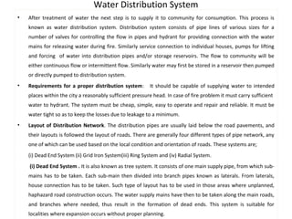
- 1. Water Distribution System • After treatment of water the next step is to supply it to community for consumption. This process is known as water distribution system. Distribution system consists of pipe lines of various sizes for a number of valves for controlling the flow in pipes and hydrant for providing connection with the water mains for releasing water during fire. Similarly service connection to individual houses, pumps for lifting and forcing of water into distribution pipes and/or storage reservoirs. The flow to community will be either continuous flow or intermittent flow. Similarly water may first be stored in a reservoir then pumped or directly pumped to distribution system. • Requirements for a proper distribution system: It should be capable of supplying water to intended places within the city a reasonably sufficient pressure head. In case of fire problem it must carry sufficient water to hydrant. The system must be cheap, simple, easy to operate and repair and reliable. It must be water tight so as to keep the losses due to leakage to a minimum. • Layout of Distribution Network. The distribution pipes are usually laid below the road pavements, and their layouts is followed the layout of roads. There are generally four different types of pipe network, any one of which can be used based on the local condition and orientation of roads. These systems are; (i) Dead End System (ii) Grid Iron System(iii) Ring System and (iv) Radial System. (i) Dead End System . It is also known as tree system. It consists of one main supply pipe, from which sub-mains has to be taken. Each sub-main then divided into branch pipes known as laterals. From laterals, house connection has to be taken. Such type of layout has to be used in those areas where unplanned, haphazard road construction occurs. The water supply mains have then to be taken along the main roads, and branches where needed, thus result in the formation of dead ends. This system is suitable for localities where expansion occurs without proper planning.
- 2. Layouts of Distribution Networks • The benefit of this system is i. The distribution network can be solved easily and accurately. The calculation of discharges and pressures at different points in the system is easy. ii. Lesser number of valves are required to control and regulate the flow of water. iii. The length of pipes needed are less iv. It is cheap and simple, and can be expanded easily. The disadvantages of the system are; i. As the water is reached through one route, any damage or repair in pipe line will completely stop the water supply in the area being fed by that pipe. ii. This system having a number of dead ends, that prevent the free circulation of water. The stagnant water may degrade the quality of water.. Thus the stale water must be removed periodically which result the wastage of potable water. iii. As the flow is from one direction. During emergency water can not be diverted from other side. Grid iron or interlaced or Reticulation system. In this system the mains, sub-mains, and branches are inter connected with each other. As in a well planned city the roads are generally developed in a grid iron pattern, and the pipelines in such places can follow them easily. This system is hence more suitable for well planned cities. Advantages of the system. i. As the flow of water is more than one route, the discharge to be carried by each pipe, the friction loss, and the size of pipe is therefore reduced. ii. In case of repairs, very small area will be deprived of supply, as some supply will reach from other routes.
- 3. Layouts of Distribution Networks iii. During fire more water can be diverted towards the affected point from various directions by closing and manipulating the various cutoff valves. iv. Due to interlinked connection, the dead ends are completely eliminated. Disadvantages . The system requires more length of pipelines, and other accessories. Construction is costly. The design is difficult, the calculation for finding the exact pipe size and the pressure at various points is a tedious job and may require the services of design experts. Ring or Circular system. In this system a closed ring, either circular or rectangular, of the main pipes is formed around the area to be served. The distribution area is divided into rectangular or circular blocks. This system is suitable for well planned roads. Ring system is used as a looped feeder placed centrally around a high demand area. Its advantages and disadvantages are like grid system. Radial System. If a city having a system of radial roads emerging from different centers, the pipe lines can be best laid in a radial method by placing the distribution reservoirs at these centers. In this system water is therefore taken from the water mains, and pumped into the distribution reservoirs placed at different centers. The water is then supplied through radially laid distribution pipes. This method ensures high pressures and efficient water distribution. The calculations for design of sizes are also simple.
- 4. Layouts of Distribution Networks
- 5. • Water Distribution methods: Water can be distributed to consumes by gravity, by pumping without storage or by combination of gravity and pumping to fulfilled the community water demand. Gravity distribution is used only when source of water supply is located at elevation from the city so that sufficient pressure is to be maintained . This type of water distribution is most dependable method, if proper control of pressure arrangements are made. For fire protection work pumping stations may be required to increase the pressure. In low lying portion of the city control valves and / or storage structures are to be used to prevent excessive pressure. Pumping without storage is the least desirable method of water distribution. In this method there will be no storage facilities, water will be lifted up by pumping and be directly flow for consumption. As consumption of water varies, the pressure fluctuates, so need several pumps to cope with the variation of demand. In case of such pumping system for fire protection high pressure is required, so individual users must be protected by pressure reducing valves. Power failure completely interruption in water supply. Also an expensive method. Pumping with storage is a common method of water distribution and is used in plain area. Water is pumped to elevated storage tanks. The excess water is stored in tanks and be consumed at maximum demand. This method helps in equalizing the pumping rate and maintain uniform pressure in the system. The stored water provides a source for fire flow and ensures a reliable general purpose when power failure occurs.. Storage tank. Water is stored to equalize pumping rate, supply and demand and to fulfilled the demand of emergencies. Elevated storage tanks are to be constructed to minimize pressure variations. Capacities of tanks depends on flow demand. In areas of maximum demand usually these tanks are to be filled at night time when demand is low. At more demand tanks provide water to the system. These tanks having automatic valve which close when tank is full and open when pressure in the mains falls below certain level.
- 6. Pressure requirement and Design of distribution system • The minimum pressure needed for distribution system also known as residual pressure is from 150 to300 KPa in residential area with four stories or less to 400-500 KPa in commercial area. Pressure in the range of 150 to 300 KPa are sufficient for normal use and fire supply. High pressure caused failure of plumbing work in houses or even in mains. In case of high valued area dual line is required, one for residential and other for fire protection at a pressure upto2100 KPa. In normal cases a motor pumper trucks is used which take water from hydrant and boost the pressure to the level necessary for the purpose. For very tall buildings fire protection may be provided by internal pumping system and stand pipes connected to external wall hydrants. • DESIGN OF DISTRIBUTION SYSTEM. Design of distribution system means using proper size of pipelines keeping in mind the proper internal and external pressure in pipe line, topography and providing proper residual pressure in the pipe lines. Design of distribution must be safe from environmental point of view. A number of methods used for design purposes some of them are. • HAZEN –WILLIAMS EQUATION. According to this equation V = KCR0.63 S0.54 where V = Flow velocity in pipe line (m/s) ; K Unit constant = 0.85 ; C= coefficient of hydraulic capacity or relative roughness of pipe. Its value is 100 to 140. High value for smooth pipe and low for rough pipe; R = Hydraulic mean depth of pipe (A/P) = d / 4 for circular pipe flowing full (m); S= Hydraulic gradient (slope); As S = hL/L where hL is the head loss and L is the length of pipe According to continuity equation Q =AV for circular pipe A = ( π/4) d2 then Q = ( π/4) d2 * V Or Q = ( π/4) d2 * (KCR0.63 S0.54 ) = ( π/4) d2 * (KC (d / 4) 0.63 (hL/L)0.54 After simplification hL = 10.68 (Q/C) 1.85 (L / d)4.87
- 7. Manning's EQUATION can also be used for pipeline discharge and head loss. According to this equation V = (R2/3 S1/2/n) As S1/2 = (hL / L)1/2 =nV / R2/3 or hL= n2 V2 L / R4/3 As R = d/4 for circular pipe; therefore hL/ L = n2 V2 L /( d/4) 1.333 or hL= 6.36 n2 V2 L / d1.333 . This equation is used when the flow is by gravity and not pressurized. DARCY WEISBACH EQUATION. According to this equation hL/ L = f’ V2 /( d 2 g) or hL = ( f’ * L / d) * (V2 /2 g) Where hL = head loss in meter: L= length of pipes (m): V = mean velocity of water in pipe (m/s) g = acceleration due to gravity: f’ = dimensionless friction factor 0.015 for new smooth pipe to 0.075 for old rough pipe: f’ = 64/ NR where NR is Reynolds number. Pipelines and appurtenances: Pipelines (closed conduit) are used where topographic conditions are not favorable for the use of channels (open conduits). pipelines may be laid above or below ground surface or partially or fully buried. Usually pressure conduits are built of concrete, steel, cast iron or polyvinyl chloride (PVC) plastics. Pipe lines required a number of gate valves, check valves, air relief valves, drains, surge control equipments, expansion joints, manholes and pumping stations. The appurtenances are provides to ensure safe and efficient operation, provide for easy inspection and facilitates maintenance. Gate valves or sluice valves. Gate valves are used to regulate the flow of water through pipelines. In large pipelines if water is conveying from a source to treatment plant the interval between gate valves should be 3 to 5 km. In case of distribution system it must not be more than 300 meters. Gate valves divide a pipelines into different segments so that if repair is required, then valve can be closed so as not to disturb the system.
- 8. • Check valves or non return valves. Check valve prevent water to flow in the opposite direction. They may be installed at the delivery side of the pumping set, so as to prevent the back flow of the stored or pumped water, when pump is stopped. Valve only allows flow in one direction. The valve automatically closes when flow begins to reverse. • Air release Valves. Air release valves are placed along the pipe line at ”summits” on both sides of the sluice value. The main purpose of air release value is to remove the accumulated air, so that free flow of water occurs. If air is present in pipe then air locked occurs and flow of water will be obstructed. • Drain values or blow off values: The values that is provided at lower level points for completely emptying the pipe for inspection or maintenance are known as drain valve. When the valve is open, water comes out quickly under gravity and pipe line is ready for maintenance. • Pressure Relief Valve. valve will begin to open when pressure in the pipeline exceed a set pressure (determined by force on the spring). Where high pressure could cause an explosion or caused to damage pipeline. • Pressure Regulating Valve. Valve will begin to open when the greater pressure is upstream than the sets-point pressure. • Expansion joints. Expansion joints are provided at suitable intervals in the pipelines to counteract the thermal stresses produced due to temperature variations. A socket and a spigot is made in such a way that one of their end is enlarged, where the other end is normal. When the pipes expands the socket moves forward and the gap left just gets closed. Similarly, when the pipes contract the socket moves backward creating the gap. All the time, the annular ring follows the movements of the socket and maintains the gasket in position , thus keeping the joint water tight.