HOA1&2 - Module 3 - PREHISTORCI ARCHITECTURE OF KERALA.pptx
communication networks
1. i
Contents
CHAPTER ONE ........................................................................................................................... 1
1.1 PDH NETWORKS (E1 - E4, T1 - T4, SONET/SDH (STS-N, STM-N, OC-N, PACKET
FORMATS/PAYLOAD.............................................................................................................. 1
1.1.1 Evolution of PDH Networks........................................................................................... 1
1.1.2 PDH IMPLEMENTATION............................................................................................ 1
1.2 SONET (SYNCHRONOUS OPTICAL NETWORK) /SDH (SYNCHRONOUS
DIGITAL HIERACHY) TECHNOLOGIES .............................................................................. 2
1.2.1 SONET/SDH EVOLUTION ....................................................................................... 2
takes place over SONE T systems. .......................................................................................... 2
1.2.2 SDH/SONET: SDH/SONET .......................................................................................... 3
1.2.4 THE BASIC UNIT OF TRANSMISSION.................................................................... 3
1.2.5 SDH FRAMING........................................................................................................... 4
1.2.6 SONET/SDH INTERLEAVING.................................................................................... 6
1.2.7 THE DIFFRENCE BETWEEN PDH AND SONET/SDH............................................ 6
1.2.8 SONET/SDH Network Management Protocols ............................................................. 7
1.2.9 Network Architectures................................................................................................ 7
1.2.10 Next-generation SONET/SDH ................................................................................... 8
CHAPTER TWO .......................................................................................................................... 9
2.1 MODEMS ............................................................................................................................. 9
2.1.1 BUILDING BLOCK OF A MODEM ............................................................................ 9
2.1.2 TYPES OF MODEMS ................................................................................................. 10
2.2.1 TYPES OF MULTIPLEXING SCHEMES ................................................................ 11
2.2.2 Time Division Multiplexing ....................................................................................... 11
2.2.3 TIME DIVISION MULTIPLEXING:.......................................................................... 12
2.2.4 COMPARISON OF FDM AND TDM................................................................... 13
2.2.5 STDM (statistical time division multiplexing) ........................................................... 14
CHATPER THREE .................................................................................................................... 15
3.1 INTRODUCTION TO MPLS (MULTIPROTOCOL LABEL SWITCHING) .............. 15
3.1.1 THE EVOLUTION OF MPLS (MULTIPROTOCOL LABEL SWITCHING) ........ 15
2. ii
3.1.2 What Is MPLS?............................................................................................................. 15
3.1.3 BENEFITS OF MPLS ................................................................................................ 16
3.1.4 MPLS AND THE INTERNET ARCHITECTURE ................................................... 17
3.1.5 MPLS NODE ARCHITECTUTRE.............................................................................. 17
4. 1
CHAPTER ONE
1.1 PDH NETWORKS (E1 - E4, T1 - T4, SONET/SDH (STS-N, STM-N, OC-N, PACKET
FORMATS/PAYLOAD
1.1.1 Evolution of PDH Networks
Until 1990s the backbone transmission networks of digital telephone networks were bases on a
technology called plesiochronous digital hierarchy (PDH).
The plesiochronous digital hierarchy (PDH) is a technology used in telecommunications
networks to transport large quantities of data over digital transport equipment such as fibre optic
and microwave radio systems. The term plesiochronous is derived from Greek plēsios, meaning
near, and chronos, time, and refers to the fact that PDH networks run in a state where different
parts of the network are nearly, but not quite perfectly, synchronized.
PDH allows transmission of data streams that are nominally running at the same rate, but
allowing some variation on the speed around a nominal rate. By analogy, any two watches are
nominally running at the same rate, clocking up 60 seconds every minute. However, there is no
link between watches to guarantee that they run at exactly the same rate, and it is highly likely
that one is running slightly faster than the other.
1.1.2 PDH IMPLEMENTATION
The European E-carrier system is described below. The basic data-transfer rate is a data stream
of 2048 kbit/s (which approximately corresponds to 2 Mbit/s if a megabit is considered as 1024
kilobits). For speech transmission, this is broken down into thirty 64 kbit/s channels plus two 64
kbit/s channels used for signaling and synchronization. Alternatively, the whole 2 Mbit/s mabe
used for non-speech purposes, for example, data transmission. The exact data rate of the 2 Mbit/s
data stream is controlled by a clock in the equipment generating the data. The exact rate is
allowed to vary by some small amount ( +5 10—5) on either side of an exact 2.048 Mbit/s. This
means that multiple 2 Mbit/s data streams can be running at slightly different rates. In order to
move several 2 Mbit/s data streams from one place to another, they are combined that is,
multiplexed in groups of four. This is done by taking one bit from stream number 1, followed by
one bit from stream number 2, then number 3, then number 4. The transmitting multiplexer also
adds additional bits in order to allow the far-end receiving demultiplexer to distinguish which
bits belong to which 2 Mbit/s data stream, and so correctly reconstruct the original data streams.
These additional bits are called justification or stuffing bits. Because each of the four 2 Mbit/s
data streams is not necessarily running at the same rate, some compensation has to be made. The
transmitting multiplexer combines the four data streams assuming that they are running at their
maximum allowed rate. This means that occasionally (unless the 2 Mbit/s is is really running at
the maximum rate) the multiplexer will look for the next bit but this will not yet have arrived. In
this case, the multiplexer signals to the receiving multiplexer that a bit is missing. This allows the
receiving multiplexer to correctly reconstruct the original data for each of the four 2 Mbit/s data
streams, and at the correct, different, plesiochronous rates. The resulting data stream from the
5. 2
above process runs at 8448 kbit/s (about 8 Mbit/s). Similar techniques are used to combine four 8
Mbit/s plus bit stuffing, giving 34 Mbit/s.
Table 1.1 below shows the details of these hierarchies.
PDH LEVEL AND BIT RATES
Carrier level North America Europe Japan
Voice/data channel 64 kbps (DS0) 64 kbps (E0) 64 kbps
First level 1.544 Mbps (DS1)
24 channels
2.048 Mbps (E1)
32 channels
1.544 Mbps
24 channels
Intermediate level 3.152 Mbps (DS1C)
48 channels
N/A N/A
Second level 6.312 Mbps (DS2)
96 channels
8.448 Mbps (E2)
128 channels
6.312 Mbps
96 channels
or
7.786 Mbps
120 channels
Third level 44.736 Mbps (DS3)
672 channels
34.368 Mbps (E3)
512 channels
32.064 Mbps
480 channels
Fourth level 274.176 Mbps (DS4)
4032 channels
139.264 Mbps (E4)
2048 channels
97.728 Mbps
1440 channels
Fifth level 400.352 Mbps (DS5)
5760 channels
565.148 Mbps (E5)
8192 channels
565.148 Mbps
8192 channels
1.2 SONET (SYNCHRONOUS OPTICAL NETWORK) /SDH (SYNCHRONOUS
DIGITAL HIERACHY) TECHNOLOGIES
1.2.1 SONET/SDH EVOLUTION
Although evolving technologies of the optical fiber due to it mass advantages like high speed,
low cost transmission, higher bandwidth, immune to electrical interference has led to the
expansion SONET and SDH. The technologies for communications services at the present time
and for the near-term future. Given the large embedded-base of these technologies in the United
States, Europe, and Asia,. Effectively, all communication in the United States between DS-3 and
OC—48 takes place over SONE T systems.
SONET was developed in the United States via the ANSI TlX1.5 committee. ANSI work
commenced in 1985 with the CCITT (now IT U) initiating a standardization effort in 1986. From
the very beginning, conflict arose between the U.S. proposals and the IT U. The United States
6. 3
wanted a data rate close to 50 Mbps in order to carry DS-I (1.544- Mbps) and DS-3 (44.736-
Mbps) signals. The Europeans needed a specifi- cation that would carry their El (2.048-Mbps),
E3 (34.368-Mbps), and 139.264-Mbps signals efficiently. The Europeans rejected the 50-Mbps
proposal as bandwidth wasteful and demanded a base signal rate close to 150 Mbps. Eventually a
compromise was reached that allowed the U.S. data rates to be a subset of the ITU specification,
known formally as SDH.
1.2.2 SDH/SONET: SDH/SONET
Synchronous optical networking (SONET) and Synchronous Digital Hierarchy (SDH), are two
closely related multiplexing protocols for transferring multiple digital bit streams using lasers
or light-emitting diodes (LEDs) over the same optical fiber . The method was developed to
replace the Plesiochronous Digital Hierarchy (PDH) system for transporting larger amounts
of telephone calls and data traffic over the same fiber wire without synchronization problems
SONET and SDH were originally designed to transport circuit mode communications (eg, T1,
T3) from variety of different sources. The primary difficulty in doing this prior to SONET was
that the synchronization source of these different circuits were different, meaning each circuit
was actually operating at a slightly different rate and with different phase. SONET allowed for
the simultaneous transport of many different circuits of differing origin within one single
framing protocol. In a sense, then, SONET is not itself a communications protocol per se, but a
transport protocol. Due to SONET's essential protocol neutrality and transport-oriented features,
SONET was the obvious choice for transporting ATM (Asynchronous Transfer Mode) frames,
and so quickly evolved mapping structures and concatenated payload containers so as to
transport ATM connections.
The two protocols are standardized according to the following
SDH or Synchronous Digital Hierarchy standard developed by the International
Telecommunication Union(ITU), documented in standard G.707 and its extension G.708
SONET or Synchronous Optical Networking standard as defined by GR-253-CORE from
Telcordia andT1.105fromAmerican National Standards Institute1.2.3 STRUCTURE
OF SONET/SDH SIGNALS
SONET and SDH often different terms to describe identical features or functions, sometimes
leading to confusion that exaggerates their diffrences.with a few exceptions. SDH can be thought
of as a superset of SONET.
The two main differences between SDH and SONET are
SONET can use either of two basic units for framing while SDH has one
SDH has additional mapping options which are not available in SONET
STS-1 frame transmitted every 125us: this a transmission rate of 52.84Mbps
1.2.4 THE BASIC UNIT OF TRANSMISSION
The basic unit of framing in SDH is a STM-1 (Synchronous Transport Module, level 1), which
operates at 155.52 megabits per second (Mbit/s). SONET refers to this basic unit as an STS-3c
(Synchronous Transport Signal 3, concatenated) or OC-3c, depending on whether the signal is
carried electrically (STS) or optically (OC), but its high-level functionality, frame size, and bit-
7. 4
rate are the same as STM-1.SONET offers an additional basic unit of transmission, the STS-1
(Synchronous Transport Signal 1) or , operating at 51.84 Mbit/s—exactly one third of an STM-
1/STS-3c/OC-3c carrier.
This speed is dictated by the bandwidth requirements for PCM-encoded telephonic voice signals:
at this rate, an STS-1/OC-1 circuit can carry the bandwidth equivalent of a standard DS-3
channel, which can carry 672 64-Kbit/s voice channels.
In SONET, the STS-3c/OC-3c signal is composed of three multiplexed STS-1 signals; the STS-
3C/OC-3c may be carried on an OC-3 signal. Some manufacturers also support the SDH
equivalent of the STS-1/OC-1, known as STM-0.
1.2.5 SDH FRAMING
In the case of an STS-1, the frame is 810 octets in size, while the STM-1/STS-3c frame is 2,430
octets in size. For STS-1, the frame is transmitted as three octets of overhead, followed by 87
octets of payload. This is repeated nine times, until 810 octets have been transmitted, taking
125 µs. In the case of an STS-3c/STM-1, which operates three times faster than an STS-1, nine
octets of overhead are transmitted, followed by 261 octets of payload.
This is also repeated nine times until 2,430 octets have been transmitted, also taking 125 µs. For
both SONET and SDH, this is often represented by displaying the frame graphically: as a block
of 90 columns and nine rows for STS-1, and 270 columns and nine rows for STM1/STS-3c. This
representation aligns all the overhead columns, so the overhead appears as a contiguous block, as
does the payload.
The internal structure of the overhead and payload within the frame differs slightly between
SONET and SDH, and different terms are used in the standards to describe these structures.
Their standards are extremely similar in implementation, making it easy to interoperate between
SDH and SONET at any given bandwidth.
8. 5
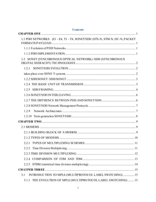
SDH FRAME
FIG 1.2
Source: Retrieved September 28, 2016, from
http://www.pcc.qub.ac.uk/tec/courses/network/SDH-SONET/sdh-sonetV1.1a_5.html
Basic frame STM-1 format consist of
270x9=2430octet
9x9=81octet section overhead
2349 octets payload
Higher rate frames are derived from multiples of STM-1 according to value of N
FIG 1.3 SDH STM-N FRAME FORMAT
Source: Retrieved September 28, 2016, from
http://www.pcc.qub.ac.uk/tec/courses/network/SDH-SONET/sdh-sonetV1.1a_5.html
9. 6
1.2.6 SONET/SDH INTERLEAVING
An STS-3 can be thought of as three STS-I bit streams transmitted in the same channel so that
the resulting channel rate is three times the rate of an STS-I. And when multiple streams of STS-
I are transmitted in the same channel, the data are octet multiplexed 131. For example, an STS-3
signal will transmit octet Al of stream 1, then octet Al of stream 2, then octet Al of stream 3, then
octet A2 of stream 1, octet A2 of stream 2, and so on .This multiplexing is carried out for all
levels of SONET and SDH, including STS-192 and STS-768. Because of this, SONET/SDH
maintains a frame time of 125 AS.
SONET/SDH DATA RATES
Table 1.2
SONET Optical Carrier
level
SONET
frame
format
SDH level
and frame
format
Payload
bandwidth(kbit/s)
Line rate
(kbit/s)
OC-1 STS-1 STM-0 50,112 51,840
OC-3 STS-3 STM-1 150,336 155,520
OC-12 STS-12 STM-4 601,344 622,080
OC-24 STS-24 STM-8 1,202,688 1,244,160
OC-48 STS-48 STM-16 2,405,376 2,488,320
OC-192 STS-192 STM-64 9,621,504 9,953,280
OC-768 STS-768 STM-256 38,486,016 39,813,120
User throughput must also deduct path overhead from the payload bandwidth, but path-overhead
bandwidth is variable based on the types of cross-connects built across the optical system.
Note that the data-rate progression starts at 155 Mbit/s and increases by multiples of four. The
only exception is OC-24, which is standardized in ANSI T1.105, but not a SDH standard rate in
ITU-T G.707.Other rates, such as OC-9, OC-18, OC-36, OC-96, and OC-1536, are defined but
not commonly deployed; most are considered orphaned rates.
1.2.7 THE DIFFRENCE BETWEEN PDH AND SONET/SDH
Synchronous networkings (SONET/SDH) differ from PDH because the exact rate that is
used to transport the data are tightly synchronized across the entire network made
possible by atomic clocks. This synchronizing system allows the entire inter-country
network to operate synchronously to reduce the amount of buffer required between
element in the network
10. 7
Both SONET/SDH can be used to encapsulate earlier digital transmission standard such
as PDH standards or used directly to support ATM or packet over SONET/SDH
networking
The basic format of SDH signal allows it to carry many different services in its virtual
container because it is bandwidth flexible
1.2.8 SONET/SDH Network Management Protocols
Network management systems are used to configure and monitor SDH and SONET equipment
either locally or remotely.
The systems consist of three essential parts, covered later in more detail:
Software running on a 'network management system terminal' e.g. workstation, dumb
terminal or laptop housed in an exchange/ central office.
Transport of network management data between the 'network management system
terminal' and the SONET/ SDH equipment e.g. using TL1/ Q3 protocols.
Transport of network management data between SDH/ SONET equipment using
'dedicated embedded data communication channels' (DCCs) within the section and line
overhead.
THE MAIN FUNCTIONS OF NETWORK MANAGEMENT THEREBY INCLUDE:
Network and network-element provisioning: In order to allocate bandwidth throughout
a network, each network element must be configured. Although this can be done locally,
through a craft interface, it is normally done through a network management system
(sitting at a higher layer) that in turn operates through the SONET/SDH network
management network.
Software upgrade: Network-element software upgrades are done mostly through the
SONET/SDH management network in modern equipment.
Performance management: Network elements have a very large set of standards for
performance management. The performance-management criteria allow not only
monitoring the health of individual network elements, but isolating and identifying most
network defects or outages.
1.2.9 Network Architectures
SONET and SDH have a limited number of architectures defined. These architectures
allow for efficient bandwidth usage as well as protection (i.e. the ability to transmit traffic
even when part of the network has failed), and are fundamental to the worldwide
deployment of SONET and SDH for moving digital traffic.
Three main architectures are:
Linear Automatic Protection Switching
Linear Automatic Protection Switching (APS), also known as 1+1, involves four fibers: two
working fibers (one in each direction), and two protection fibers. Switching is based on the line
state, and may be unidirectional (with each direction switching independently), or bidirectional
11. 8
(where the network elements at each end negotiate so that both directions are generally carried
on the same pair of fibers).
Unidirectional path-switched ring
In unidirectional path-switched rings (UPSRs), two redundant (path-level) copies of protected
traffic are sent in either direction around a ring. A selector at the egress node determines which
copy has the highest quality, and uses that copy, thus coping if one copy deteriorates due to a
broken fiber or other failure. UPSRs tend to sit nearer to the edge of a network, and as such are
sometimes called collector rings.The SDH equivalent of UPSR is subnetwork connection
protection (SNCP); SNCP does not impose a ring topology, but may also be used in mesh
topologies.
Bidirectional line-switched ring
Bidirectional line-switched ring (BLSR) comes in two varieties: two-fiber BLSR and four-fiber
BLSR. BLSRs switch at the line layer. Unlike UPSR, BLSR does not send redundant copies
from ingress to egress. Rather, the ring nodes adjacent to the failure reroute the traffic "the long
way" around the ring on the protection fibers. BLSRs trade cost and complexity for bandwidth
efficiency, as well as the ability to support "extra traffic" that can be pre-empted when a
protection switching event occurs. fiber connecting two nodes to be used rather than looping it
around the ring.The SDH equivalent of BLSR is called Multiplex Section-Shared Protection
Ring (MS-SPRING).
1.2.10 Next-generation SONET/SDH
SONET/SDH development was originally driven by the need to transport multiple PDH
signals—like DS1, E1, DS3, and E3—along with other groups of multiplexed 64 kbit/s pulse-
code modulated voice traffic. The ability to transport ATM traffic was another early application.
In order to support large ATM bandwidths, concatenation was developed, whereby smaller
multiplexing containers (e.g., STS-1) are inversely multiplexed to build up a larger container
(e.g., STS-3c) to support large data-oriented pipes.
One problem with traditional concatenation, however, is inflexibility. This problem was
overcome with the introduction of Virtual Concatenation.
Virtual concatenation (VCAT) allows for a more arbitrary assembly of lower-order
multiplexing containers, building larger containers of fairly arbitrary size (e.g., 100 Mbit/s)
without the need for intermediate network elements to support this particular form of
concatenation.
The Link Capacity Adjustment Scheme (LCAS) allows for dynamically changing the
bandwidth via dynamic virtual concatenation, multiplexing containers based on the short-term
bandwidth needs in the network.
12. 9
CHAPTER TWO
2.1 MODEMS
Modem is abbreviation for Modulator – Demodulator. Modems are used for data transfer
from one computer network to another computer network through telephone lines. The computer
network works in digital mode, while analog technology is used for carrying massages across
phone lines.
Modulator converts information from digital mode to analog mode at the transmitting end and
demodulator converts the same from analog to digital at receiving end. The process of converting
analog signals of one computer network into digital signals of another computer network so they
can be processed by a receiving computer is referred to as digitizing.
When an analog facility is used for data communication between two digital devices called Data
Terminal Equipment (DTE), modems are used at each end. DTE can be a terminal or a computer.
FIG 2.1
Source: Retrieved September 28, 2016, from
http://ecomputernotes.com/images/Modulation-and-Demodulation.jpg
The modem at the transmitting end converts the digital signal generated by DTE into an analog
signal by modulating a carrier. This modem at the receiving end demodulates the carrier and
hand over the demodulated digital signal to the DTE.
2.1.1 BUILDING BLOCK OF A MODEM
The transmission medium between the two modems can be dedicated circuit or a switched
telephone circuit. If a switched telephone circuit is used, then the modems are connected to the
13. 10
local telephone exchanges. Whenever data transmission is required connection between the
modems is established through telephone exchanges.
FIG 2.2
Source: Retrieved September 28, 2016, from http://ecomputernotes.com/images/Building-
Blocks-of-a-Modem.jpg
2.1.2 TYPES OF MODEMS
Wireless Modems
Wireless modems transmit the data signals through the air instead of by using a cable. They
sometimes are called radio frequency modem. This type of modem is designed to work with
cellular technology, and wireless local area networks. Wireless modems use two types of
transmission to transfer their data; radio transceivers and infrared (IR). Radio transceiver
modems have three ways of transmitting data; transceiver-transceiver, transceiver-satellite-
transceiver, and cellular phone. Radio transceiver-transceiver can be used as point-point or point-
multipoint operation and generally transmit at the frequency of 900 MHz. Radio transceiver
modems have advantages and disadvantages when compared with a wired modem
Fax Modems: These allow you to send and receive faxes. The fax part of the modem
sends/receives data that is interpreted as a picture. One can create documents on a computer
(resumes, papers, thesis proposals) and send them directly from the application to a fax machine
or a computer with a fax modem. Instead of sending the print job to the printer you're sending it
to the fax modem.
Standard Modems: An internal modem is used inside of the computer and connects directly to
the I/O BUS. The internal modem does not require a separate power supply as it gets it's power
from the computer's internal BUS nor does an internal modem require a serial port or connecting
cables to that port. An internal modem will contain a 16550A UART or equivalent circuitry,
which will aid in fast data throughput to the computer. Internal modems are usually cheaper
14. 11
2.2 MULTIPLEXING
In telecommunications and computer networks, multiplexing (sometimes contracted to
muxing) is a method by which multiple analog or digital signals are combined into one signal
over a shared medium. The aim is to share an expensive resource. For example, in
telecommunications, several telephone calls may be carried using one wire. The device that
performs multiplexing is called multiplexer.
In electronics, a multiplexer (or mux) is a device that selects one of several analog or digital
input signals and forwards the selected input into a single line. A multiplexer of 2n inputs has n
select lines, which are used to select which input line to send to the output. Multiplexers are
mainly used to increase the amount of data that can be sent over the network within a certain
amount of time and bandwidth. A multiplexer is also called a data selector. Multiplexers can
also be used to implement Boolean functions of multiple variables.
Conversely, a demultiplexer (or demux) is a device taking a single input signal and selecting
one of many data-output-lines, which is connected to the single input. A multiplexer is often
used with a complementary multiplexer on the receiving end.
2.2.1 TYPES OF MULTIPLEXING SCHEMES
2.2.2 Time Division Multiplexing: Frequency Division Multiplexing (FDM) : In FDM, many
signals are transmitted simultaneously where each signal occupies a different frequency slot
within a common bandwidth. Usually, FDM systems are used in analog communication.
Frequency Division Multiplexing (FDM) Multiplexing requires that the signals be kept apart so
that they do not interfere with each other, and thus they can be separated at the receiving end.
This is accomplished by separating the signal either in frequency or time. The technique of
separating the signals in frequency is referred to as frequency division multiplexing (FDM),
whereas the technique of separating the signals in time is called time division multiplexing. In
this section, we discuss frequency division multiplexing systems, referred hereafter as FDM.
FIG 2.3 shows the block diagram of FDM system. As shown in the Fig 2.3 input message
signals, assumed to be of the low-pass type are passed through input low-pass filters. This
filtering action removes high-frequency components that do not contribute significantly to signal
representation but may disturb other message signals that share the common channel. The
filtered message signals are then modulated with necessary carrier frequencies with the help of
modulators. The most commonly method of modulation in FDM is single sideband modulation
which requires a bandwidth that is approximately equal to that of original message signal. The
band pass filters following the modulators are used to restrict the band of each modulated wave
to its prescribed range. The outputs of band-pass filters are combined in parallel which form the
input to the common channel
15. 12
BLOCK DIAGRAM OF FDM SYSTEM
FIG 2.2
Source: A.P.Godse, U. A. B. (2010). Analog communication. Retrieved from
https://books.google.com.gh/books.
The outputs of band-pass filters are combined in parallel which form the input to the common
channel. At the receiving end, bandpass filters connected to the common channel separate the
message signals on the frequency occupancy basis. Finally, the original message signals are
recovered by individual demodulators.
Advantages of FMM
Number of signals can be transmitted simultaneously.
Only a single channel gets affected due to slow narrow band fading.
Do not require synchronization between transmitter and receiver
Disadvantages of FDM
Requires larger bandwidth of communication channel.
More number of modulators and filters are required
Requires complex circuitry at transmitter and receiver
Suffers from crosstalk problem due to imperfect bandpass filter
Requires larger bandwidth of communication channel.
Applications of FDM
In radio broadcasting using AM (Amplitude Modulation) and FM (Frequency Modulation).
In TV broadcasting
2.2.3 TIME DIVISION MULTIPLEXING:
Time Division Multiplexing (TDM) : In TDM, the signals are. Not transmitted at a time;
however, they are transmitted in different time slots. Usually, TDM systems are used in digital
communication.
16. 13
BLOCK DIAGRAM OF TDM SYSTEM
FIG 2.3
Source: A.P.Godse, U. A. B. (2010). Analog communication. Retrieved from
https://books.google.com.gh/books
As the number of messages to be transmitted increases, the frequency division technique presents
problems. The number of subcarriers needed increases, and stability problems can arise.
Additional circuitry is required, both at transmitting and receiving ends to handle each added
channel. The bandwidth requirements increase directly with the number of channels. These
problems are eliminated to a great extent by using Time Division Multiplexing (TDMI, together
with pulse modulation. In TDM, each intelligence signal to be transmitted (voice or telemetry
data) is sampled sequentially and the resulting pulse code is used to modulate the carrier. The
same carrier frequency is used to transmit different pulses sequentially, one after other, thus each
intelligence, to be transmitted, has been allotted a given time slot. Since only one signal
modulates the carrier at any time, no added equipment and no increase in bandwidth is needed
when multiplexing. The number of sequential channels that can be handled is limited by the time
span required by any one channel pulse and the interval between samples.
2.2.4 COMPARISON OF FDM AND TDM
The FDM and TDM, being multiplexing techniques, accomplish the same goal, i.e. transmitting
more than one message, on the same channel. Thus they are dual techniques. Frequency Division
Multiplexing requires modulators, filters, demodulators ; while Time Division Multiplexing
require commutator at the transmitting end and a distributor, working in perfect synchronism
with commutator at the receiving end. A perfect synchronism between transmitter and receiver is
absolutely essential for proper operation of T DM system. Thus TDM synchronization is more
demanding than that of FDM with suppressed-carrier modulation. For demodulating the SSB
signal used in FI)M: the carrier is locally generated in the receiver.
.
Advantages of TDM
1. Entire channel bandwidth can be utilized for each channel.
2. In TDM, intermodulation distortion is absent.
3. Crosstalk problem is not severe in TDM.
17. 14
4. Does not require very complex circuitry.
Disadvantages of TDM
1. Perfect synchronization between transmitter and receiver is required.
2. All T DM channels may get affected due to slow narrow fading.
2.2.5 STDM (statistical time division multiplexing)
STDM, or statistical time division multiplexing, is one method for transmitting several types of
data simultaneously across a single transmission cable or line (such as a T1 or T3 line). STDM is
often used for managing data being transmitted via a local area network (LAN) or a wide area
network (WAN). In these situations, the data is often simultaneously transmitted from any
number of input devices attached to the network, including computers, printers, or fax
machines.STDM can also be used in telephone switchboard settings to manage the simultaneous
calls going to or coming from multiple, internal telephone lines.
BLOCK DIAGRAM OF STDM
FIG 2.5
Source: A.P.Godse, U. A. B. (2010). Analog communication. Retrievedfrom
https://books.google.com.gh/books.
The concept behind STDM is similar to TDM, or time division multiplexing. TDM allows
multiple users or input devices to transmit or receive data simultaneously by assigning each
device the same, fixed amount of time on one of many "channels" available on the cable or line.
The TDM method works well in many cases, but does not always account for the varying data
transmission needs of different devices or users
Disadvantages of STDM
1. The channel capacity cannot be fully utilized. Some of the slots go empty in certain frames. 2.
2. The capacity of single communication line that is used to carry the various transmissions
should be greater than the total speed of input lines.
18. 15
CHATPER THREE
3.1 INTRODUCTION TO MPLS (MULTIPROTOCOL LABEL SWITCHING)
MPLS is introduced as a technology that is driving future IP networks including the Internet. It
describes MPLS as providing a new forwarding paradigm for the Internet, which has affected its
traffic engineering, quality of service as well as the implementation of Virtual Private Networks.
It also details the various other benefits obtained by implementing MPLS in core backbone
networks.
3.1.1 THE EVOLUTION OF MPLS (MULTIPROTOCOL LABEL SWITCHING)
The initial goal of label-based switching was to bring the speed of Layer 2 switching to Layer 3.
This initial justification for technologies such as MPLS is no longer perceived as the main
benefit, because newer Layer switches using application-specific integrated circuit (ASIC)-based
technology can perform route lookups at sufficient speeds to support most interface types.
The widespread interest in label switching initiated the formation of the IETF MPLS working
group in 1997.
MPLS has evolved from numerous prior technologies, including proprietary versions of label-
switching implementations such as Cisco's Tag Switching, IBM's Aggregate Route- Based IP
Switching (ARIS), Toshiba's Cell-Switched Router (CSR), Ipsilon's IP Switching, and Lucent's
IP Navigator. Tag Switching, invented by Cisco, was first shipped to users in March 1998. Since
the inception of Tag Switching, Cisco has been working within the IETF to develop and ratify
the MPLS standard, which has incorporated most of the features and benefits of Tag
Switching.
Cisco currently offers MPLS support in its version 12-r releases of IOS.
3.1.2 What Is MPLS?
MPLS is an improved method for forwarding packets through a network using information
contained in labels attached to IP packets. The labels are inserted between the Layer 3 header
and the Layer 2 header in the case of frame-based Layer 2 technologies, and they are contained
in the virtual path identifier (VPI) and virtual channel identifier (VCI) fields in the case of cell-
based technologies such as ATM. MPLS combines Layer 2 switching technologies with Layer 3
routing technologies. The primary objective of MPLS is to create a flexible networking fabric
that provides increased performance and stability. This includes traffic engineering and VPN
capabilities. Which
offer quality of service (QoS) with multiple classes of service (COS). In an MPLS network (see
Figure I-I ), incoming packets are assigned a label by an Edge Label-Switched Router. Packets
are forwarded along a Label-Switched Path (LSP) where each Label-Switched Router (LSR)
makes forwarding decisions based solely on the label's contents. At each hop, the LSR strip off
19. 16
the existing label and applies a new label. This tells the next hop how to forward the packet. The
label is stripped at the egress Edge LSR. and the packet is forwarded to its destination.
The MPLS Network Topology
NOTE: The term multiprotocol means MPLS techniques are applicable to any network layer
protocol
FIG 3.1 MPLS Network Topology
Source: Alwayn, V. (2001). Advanced MPLS design and implementation. Retrieved from
https://books.google.com.gh/books?
3.1.3 BENEFITS OF MPLS
VPNs—Using MPLS: service providers can create Layer 3 VPNs across their backbone network
for multiple customers, using a common infrastructure, without the need for encryption or end-
user applications.
Traffic engineering: Provides the ability to explicitly set single or multiple paths that the traffic
will take through the network. Also provides the ability to set performance characteristics for a
class of traffic. This feature optimizes bandwidth utilization of underutilized paths.
Quality of service: Using MPLS quality of service (QOS), service providers can
provide multiple classes of service with hard QoS guarantees to their VPN customers.
Integration of IP and ATM: Most carrier networks employ an overlay model in
which ATM is used at Layer 2 and IP is used at Layer 3. Such implementations have major
20. 17
scalability issues. Using MPLS, carriers can migrate many of the functions of the ATM control
plane to Layer 3, thereby simplifying network provisioning, and network complexity .
3.1.4 MPLS AND THE INTERNET ARCHITECTURE
Ever since the deployment of ARPANET. The forerunner of the present-day Internet, the
architecture of the Internet has been constantly changing. It has evolved in response to
advances in technology, growth, and offerings of new services. The most recent change to the
Internet architecture is the addition of MPLS.
It must be noted that the forwarding mechanism of the Internet, which is based on destination
based routing has not changed since the days of ARPANET. The major changes have been the
migration to Border Gateway Protocol Version 4 (BGP4) from Exterior Gateway Protocol
(EGP). The implementations of classless inter domain routing (CIDR), and the constant upgrade
of bandwidth and termination equipment such as more powerful routers.
MPLS has impacted both the forwarding mechanism of IP packets and path determination (the
path the packets should take while transiting the Internet). This has resulted in a fundamental
architecture of the Internet.
MPLS can simplify the deployment of IPv6 because the forwarding algorithms used by MPLS
for IPv4 can be applied to IPv6 with the use of routing protocols that support IPv6 addresses.
MPLS is being deployed because it has an immediate and direct benefit to the Internet. The most
immediate benefit of MPLS with respect to an Internet service provider's backbone network is
the ability to perform traffic engineering.
Traffic engineering allows the service provider to offload congested links and engineer the load
sharing over underutilized links. This results in a much higher degree of resource utilization that
translates into efficiency and cost savings. Internet VPNs are currently implemented as IP
Security (IPSec) tunnels over the public Internet. Such VPNs, although they do work, have a
very high overhead and are slow. MPLS VPNs over the Internet let service providers offer
customers Internet-based VPNs with bandwidth and service levels comparable to traditional
ATM and Frame Relay services
Another disadvantage of GRE and IPSec tunnels is that they are not scalable. MPLS VPNs can
be implemented over private IP networks. IP VPN services over MPLS backbone networks can
be offered at a lower cost to customers than traditional Frame Relay or ATM VPN services due
to the lower cost of provisioning, operating, and maintaining MPLS VPN services. MPLS traffic
engineering can optimize the bandwidth usage of underutilized paths. ms can also result in cost
savings that can be passed on to the customer
MPLS QoS gives the service provider the ability to offer multiple classes of service to
customers, which can be priced according to bandwidth and other parameter
3.1.5 MPLS NODE ARCHITECTUTRE
The MPLS have two architectural planes:
MPLS Forward Plane
MPLS Control Plane
MPLS planes can perform layer 3routing or layer 2 switching in addition to switching labels
packet
21. 18
FIG 3.2 MPLS Node Architecture
Source: Alwayn, V. (2001). Advanced MPLS design and implementation. Retrieved from
https://books.google.com.gh/books
The MPLS forwarding plane is responsible for forwarding packets based on values contained
in attached labels.
The forwarding plane uses a label forwarding information base (LFIB) maintained by the MPLS
node to forward labeled packets. The algorithm used by the label switching forwarding
component uses information contained in the LFIB as well as the information contained in the
label value. Each MPLS node maintains two tables relevant to MPLS forwarding: the label
information base (LIB) and the LFIB. The LIB contains all the labels assigned by the local
MPLS node and the mappings of these labels to labels received from its MPLS neighbors. The
LFIB uses a subset of the labels contained in the LIB for actual packet forwarding.
The MPLS control plane: The MPLS control plane is responsible for populating and
maintaining the LFIB. All MPLS nodes must run an IP routing protocol to exchange IP routing
information with all other MPLS nodes in the network. MPLS enabled ATM nodes would use an
external Label Switch Controller (LSC) such as a 7200 or 7500 router or use a Built-in Route
Processor Module (RPM) in order to participate in the IP routing process. Link-state routing
protocols such as OSPF and IS-IS are the protocols of choice, because they provide each MPLS
node with a view of the entire network. In conventional routers, the IP routing table is used to
build the Fast Switching cache or the Forwarding Information Base (FIB) used by Cisco Express
Forwarding (CEF). However, in MPLS, the IP routing table provides information on destination
network and subnet prefixes used for label binding.