Engineering Services RFP - PEC VDOT Rappahannock Fish-Passage Pilot Project - Piney River
•
0 j'aime•407 vues

June 26, 2020 -- PEC seeks to secure contracted professional engineering services to complete (1) a Geotechnical Report and (2) a Final Design for fish-friendly and flood-resilient structures to replace culverts at ONLY the Piney River (VA Rt. 653) pilot project site in Rappahannock County, VA.

Recommandé
Recommandé
Contenu connexe
Tendances
Tendances (20)
Similaire à Engineering Services RFP - PEC VDOT Rappahannock Fish-Passage Pilot Project - Piney River
Similaire à Engineering Services RFP - PEC VDOT Rappahannock Fish-Passage Pilot Project - Piney River (20)
Plus de The Piedmont Environmental Council
Plus de The Piedmont Environmental Council (20)
Dernier
Dernier (20)
Engineering Services RFP - PEC VDOT Rappahannock Fish-Passage Pilot Project - Piney River
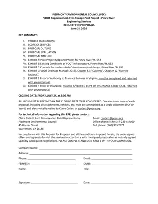
- 1. PIEDMONT ENVIRONMENTAL COUNCIL (PEC) VDOT Rappahannock Fish-Passage Pilot Project - Piney River Engineering Services REQUEST FOR PROPOSALS June 26, 2020 RFP SUMMARY: I. PROJECT BACKGROUND II. SCOPE OF SERVICES III. PROPOSAL OUTLINE IV. PROPOSAL EVALUATION V. PROPOSAL TIMELINE VI. EXHIBIT A: Pilot Project Map and Photos for Piney River/Rt. 653 VII. EXHIBIT B: Existing Conditions of VDOT infrastructure, Piney River/Rt. 653 VIII.EXHIBIT C: Contech Bottomless Arch Culvert conceptual design, Piney River/Rt. 653 IX. EXHIBIT D: VDOT Drainage Manual (2019), Chapter 8.3 “Culverts”, Chapter 12 “Riverine Analysis” X. EXHIBIT E, Proof of Authority to Transact Business in Virginia, must be completed and returned with your proposal. XI. EXHIBIT F, Proof of Insurance, must be A VERIFIED COPY OF INSURANCE CERTIFICATE, returned with your proposal. CLOSING DATE: FRIDAY, JULY 24, at 5:00 PM ALL BIDS MUST BE RECEIVED BY THE CLOSING DATE TO BE CONSIDERED. One electronic copy of each proposal, including all attachments, exhibits, etc. must be summarized as a single document (PDF or Word) and electronically mailed to Claire Catlett at ccatlett@pecva.org For technical information regarding this RFP, please contact: Claire Catlett, Land Conservation Field Representative Email: ccatlett@pecva.org Piedmont Environmental Council Office phone: (540) 347-2334 x7060 45 Horner Street Cell phone: (540) 935-7677 Warrenton, VA 20186 In compliance with this Request for Proposal and all the conditions imposed herein, the undersigned offers and agrees to furnish the services in accordance with the signed proposal or as mutually agreed upon by subsequent negotiations. PLEASE COMPLETE AND SIGN PAGE 1 WITH YOUR SUBMISSION. Company Name: __________________________________________________________________ Address: _________________________________________________________________________ Phone: __________________________________ Email: _____________________________ FEIN/SSN: ________________________________ DUNS: _____________________________ Name: ___________________________________ Title: ______________________________ Signature: _________________________________ Date: ______________________________
- 2. 2 I. PROJECT BACKGROUND PEC is one of the most effective community-based environmental groups in the country that has worked since 1972 to promote and protect the natural resources, rural economy, history and beauty of the Virginia Piedmont. As a 501-C(3) non-profit and accredited land trust, our work empowers citizens and their communities of our nine-county region to conserve land, strengthen rural economies, celebrate historic resources, protect air and water quality, build smart transportation networks, promote sustainable energy choices, restore wildlife habitat, and improve people’s access to nature. PEC believes that the most important resource that our communities share is clean water. PEC is restoring trout streams in Virginia’s Piedmont to connect fish passage and restore water quality. Eastern brook trout are an indicator species for water quality because they need cold, clean water to survive, and also have become a charismatic species for headwater stream health. As a land trust and non-profit, PEC uniquely works on collaborative initiatives with public and private landowners as conservation partners, and has extended our work for trout stream restoration in the Upper Rappahannock watershed (includes Rappahannock, Orange, Madison, and Greene County). As of 2019, PEC, VDOT and U.S. Fish and Wildlife Service (USFWS) are working together to complete two pilot projects for trout stream restoration in Rappahannock County. VDOT and PEC have selected two pilot projects at public road-stream crossing locations at Piney River (VA Rt. 653) and Bolton Branch (VA Rt. 631) during the project timeline of 2020-2021. PEC has secured the projects’ funds through several federal grants, and will rely on VDOT and USFWS to lead the project’s scope of work with their expertise and technical assistance. II. SCOPE OF SERVICES PEC seeks to secure contracted professional engineering services to complete (1) a Geotechnical Report and (2) a Final Design for fish-friendly and flood-resilient structures to replace culverts at ONLY the Piney River (VA Rt. 653) pilot project site in Rappahannock County, VA. The selected engineering firm will have experience in stream restoration and VDOT transportation engineering, as well as hold an engineering license in Virginia. This RFP will ensure competitive costs for PEC and all partners, and meet federal funding guidance, as given by the OMB Circular. The pilot project included in the Scope of Services in this RFP will be the stream culvert-crossing replacement located at Piney River, on Sycamore Ridge Rd. (VA Rt. 653), near Sperryville, VA (38.694270, -78.259068). This project is located on VDOT Right-of-Way. A 30% conceptual design, hydraulic analysis, stream surveys, and site mapping has been completed in the first phase of this project by USFWS. The selected engineering firm will complete the final design for Piney River, with targeted construction dates of spring 2021 (see Project Timeline below). The selected engineering contractor will complete the associated tasks (see below). The selected engineering firm will use existing conditions calculations for hydrology and preliminary designs completed by USFWS to recommend a final design for Piney River. PEC and VDOT have developed a MOA to indicate this project’s scope of work, timeline, as well as procedures for payment and exchange of services.
- 3. 3 Please see Exhibit A for project map. Exhibits B details existing conditions of VDOT infrastructure at Piney River. Exhibit C details an example of a fish-friendly, full aquatic organism passage (AOP) structure- - a bottomless-arch culvert-- to replace the existing structure at Piney River. Exhibit D includes VDOT Drainage Manual (2015) sections for countersinking culverts and fish-passage. An Engineering Contract will include the following tasks for a Final Design, Site Plan (as required by VDOT), and an As-Built Survey, but are not limited to: A. Preliminary Design Review: USFWS has completed stream surveys and existing conditions hydraulic analysis at the Piney River project. A USFWS conceptual design has developed a full Aquatic Organism Passage (AOP) solution at Piney River. The selected engineering firm will review these preliminary design documents in preparation of a final design, and/or any design alternatives for Piney River. An example for a full-AOP, bottomless-arch culvert fabrication for Piney River is attached (Exhibit E). The engineering firm will provide the following services as a completed preliminary design review: ● preliminary soils survey and pavement investigation survey ● preliminary roadway approach design - Preliminary Field Inspection/PFI level (ROW and easements labeled, impacts to utilities and property owners defined, etc.) ● concept structure layout and construction phasing with a Stage I Report and preliminary engineers cost estimate ● Preliminary Maintenance of Traffic/MOT plans and time estimate of traffic impacts during construction (maybe alternatives for MOT since on dead end road) ● Preliminary river hydraulic analysis including existing and proposed conditions hydraulic modeling (HEC-RAS) for VDOT review and approval. B. Geotechnical Services & Report: Engineering contractor will secure geotechnical services and a report, inclusive of the following tasks (but not limited to): ● Public and private utility identification ● subsurface exploration, including borings field engineering and soil samples ● groundwater surveys ● recommendations regarding preparation of subgrades ● evaluation of on-site soil, including compaction criteria and excavation techniques ● foundation design ● on-site testing during construction ● a final report that summarizes completed work as a Site Vicinity Map, Location Plan, and Summary of Lab Tests. C. Final Design/ Site Plan: Engineering contractor will provide a 100% set of construction plans including the relevant engineering analyses and calculations at Piney River. The final design issued for the final construction plans will include all information necessary for the successful construction of the proposed practices including: ● right-of-way and construction plans
- 4. 4 ● structure and bridge design (final plans, construction specifications, estimate and special provisions) ● final roadway approach design ● survey, including preliminary and final land acquisition R/W plats ● hydrologic design (including erosion and sediment control design) ● Final river hydraulic analysis (including scour analysis) in a signed and sealed report. ● No adverse impact statement VDOT form LD293 & LD294 (needed for permitting) ● traffic engineering design, (including sign, signal, pavement marking plans) ● geotechnical foundation analysis and design ● traffic management plans (TMP) ● development of live load ratings ● permit sketches ● Contract Time Determination Reviews/CTDR (2 alternatives - 1 for normal work hours and 1 with accelerated or multiple crews working to develop incentive) with specified duration to traffic impacts D. Permitting Compliance: VDOT will apply for all project permits, and the selected engineer will provide associated project coordination to VDOT during all permitting applications, administration, and close-out tasks. E. As-built Survey: After the construction at the Piney River project is completed, the engineering contractor will conduct an as-built survey that may include: ● in-stream features ● road-stream crossing structures ● associated landscaping ● a profile with monumental cross-sections ● load ratings ● and photographic monitoring stations ● As-Built river hydraulic analysis if significant deviations from the design plans are discovered in the roadway profile or the in-stream structure elevations. F. Construction Support Services: The engineer will review all work completed during construction, and document that all project components have been installed according to the final plans. The engineer will additionally provide design support during construction including, but not limited to: ● attending partnering and other construction related meetings ● attending partner presentations showcasing pilot project ● formal plan revisions (not related to design error) ● prompt design reviews and revisions to prevent work order claims, participation in construction value engineering and constructability reviews ● shop drawing reviews, review of contractor’s working drawings and responding to contractor inquiries ● provide as-built plans and load rating
- 5. 5 ● reference points, markers, and offsets to guide construction G. Warranty: PEC will negotiate a warranty for all engineering/design work associated with each project’s final design, and such warranty will be approved by VDOT per terms identified in the PEC-VDOT MOU. III. PROPOSAL OUTLINE The following information and clarification is provided to assist in the preparation of the proposal: a. Qualifications of offeror: The offeror must be fully qualified to perform the described services for the scope of work as described herein. Preference will be given to offerors with demonstrated experience with stream restoration and bridge installation project work. The offeror must submit at least three (3) samples of relevant related work history of similar scope, size and complexity that has been completed in the past two years. Offeror shall submit copies of Professional Engineering Licenses for those individuals responsible for signing and sealing the plans and engineering reports. b. Offerors are to submit written proposals that present the offeror’s qualifications and understanding of the work to be performed. The offeror’s proposal should be prepared simply and economically and should provide all the information which it considers pertinent to its qualifications for the project and which respond to the Project Background and Scope of Services criteria listed herein. Emphasis should be placed on completeness of services offered and clarity of content. c. Any questions related to this Request for Proposal should be submitted in writing or via email to the Point of Contact listed on the first page no later than May 30, 2020. This will allow for adequate time to respond to the question and to notify all bidders of the answer. d. If subcontractors or business partners will be used during the performance of this contract, they must be identified in the proposal. e. The offeror is responsible for all costs incurred in the development and submission of the proposal. f. EXHIBIT G, Proof of Authority to Transact Business in Virginia, must be completed and returned with your proposal. g. EXHIBIT H, Proof of Insurance, must be completed and returned with your proposal. IV. PROPOSAL EVALUATION All qualified proposals will be evaluated by the Piedmont Environmental Council (PEC) and Virginia Department of Transportation (VDOT) using the following criteria: ● Specific plan or methodology to be used to perform the services ● Experience and qualifications of personnel assigned to perform the services: The proposal must identify the project manager, specific names of persons assigned to conduct the tasks, and qualifications of the individuals. Do not include firm accomplishments unless persons assigned to work on this proposal were part of those projects. ● Proposed time frame and ability to perform the services: Offeror should provide a timeline for completion of the project from start to finish within the firm’s existing work load.
- 6. 6 ● Ability to work closely with PEC, USFWS and VDOT’s designated representative: The Offeror will be required to work closely with the PEC’s designated project manager, as well as the project partners, including VDOT and USFWS. ● Understanding of the project: Offeror should include a description of their understanding of the project in the narrative provided as part of their proposal. V. Competitive cost (as a Project Budget): All bids will be comparatively assessed for competitive costs. VI. PROJECT TIMELINE TASK MILESTONE RFP posted JUNE 26, 2020 Deadline for submission of questions about RFP JULY 17, 2020 PROPOSALS DUE/Receive proposals JULY 24, 2020 Award contract JULY 31, 2020 Begin contract AUGUST 7, 2020 Project construction APRIL 2021 (Piney R.) Project completion MAY 1, 2021 Final billing MAY 15, 2021
- 7. EXHIBIT A: Pilot Project Map and Photos for Piney River/Rt. 653
- 8. Structure #306 Shenandoah National Park PickeralRidgeLn Hull School Rd SycamoreRidgeRd Swindler Hollow Rd N o r t h F ork ThorntonRiver P i n e y R i v e r Thompson 56 Nelson 61 Ringer 101 6 6 Atkins 1 Johnston 51 Johnston 6 Snay 2 Rowlett 2 Wilson 2 Kirby 1 Hager 20 Burke 12 Ubelaker 29 Tuttle 49 Lynch 28 Elkins 1 Biby 9 Parsons 3 Clatterbuck 4 Heller 40 Burney 53 Miller 9 Boelte 11 Heller 2 Mathison 85 Stone 89 6 8 4 94 2 1 6 2 9 83 72Piney River 0 500 1,000 Feet q Map created by PEC for presentation purposes only. Data source: County Governments, the Virginia Department of Conservation and Recreation, the Virginia Department of Historic Resources, the Virginia Base Mapping Program, the National Wetland Inventory, American Battlefield Protection Program and the National Hydrology Dataset. Although efforts have been made to verify data, accuracy is not guaranteed. April 20, 2017 | Warrenton | JWR Virginia Scenic Road Wetland Flood Zones FEMA Conservation Easements Publicly Owned Land Historic Districts River / Streams Intermittent Streams ! Warrenton ! Culpeper ! Front Royal !Washington ! Manassas FAUQUIER RAPPAHANNOCK CULPEPER WARREN LOUDOUN PRINCE WILLIAM STAFFORDMADISON FREDERICK FAIRFAX Leesburg ! Madison Area of Detail ! ! Winchester ! Berryville VDOT #306 Sycamore Ridge Rd./ Rt. 653 38.694270, -78.259068
- 9. Piney River – Upstream
- 10. Piney River – Downstream
- 11. EXHIBIT B: Existing Conditions of VDOT infrastructure, Piney River/Rt. 653
- 14. EXHIBIT C: Contech Bottomless Arch Culvert conceptual design, Piney River/Rt. 653
- 15. 9025 Centre Pointe Dr. West Chester, OH 45069 800-338-1122 www.ContechES.com © 2012 Contech Engineered Solutions LLC ENGINEERED SOLUTIONS • Over 7,000 installations since 1976 • Spans to 35 ft • Wide-span, low-rise structures • Ideal for small bridge replacements • Variety of shapes and sizes • Lightweight • Fast, easy, low cost installation • Suitable for rehabilitation • Extensive technical support • Economical solution Aluminum Box Culvert - stream crossing Aluminum Box Culvert - county road bridge Aluminum Box Culvert - multi-cell installation Aluminum Box Culvert - stream crossing Aluminum Box Culvert Aluminum Box Culvert - aesthetic finish Plate
- 16. Contech Engineered Solutions LLC 9025 Centre Pointe Drive, Suite 400 West Chester, OH 45069 Phone: (513) 645-7000 Fax: (513) 645-7993 www.ContechES.com March 16, 2020 Project: Culvert Crossing, Huntly VA (DYOB REFERENCE #216834) Jessica Pica US Fish and Wildlife Service 300 Westgate Center Drive Hadley, MA 01035 As requested, the following is a Contech Aluminum Box Culvert System ENGINEER’S COST ESTIMATE for the above referenced project. This ESTIMATE is intended for preliminary estimating purposes only and should not be interpreted as a final QUOTATION. The information presented is based on the DYOB referenced above. Contech will fabricate and deliver the following described Aluminum Box Culvert System components and appurtenances: DESCRIPTION OF SUPPLIED MATERIALS: § Contech Aluminum Box Culvert Structure Number 82 § 18.25 L.F. of Structure Number 82, 25'-2" Span x 6'-2" Rise Aluminum Box Culvert § Shell Designation = E6 § Two (2) Aluminum headwalls with anchors and connection hardware § Four (4) Aluminum wingwalls with deadman anchors and connection hardware *ESTIMATE - $32,500 Delivered These costs do not include the foundation, or installation costs. As part of the construction process, the contractor is to perform the items listed below in accordance with the installation drawings: § Construct cast-in-place foundations (if applicable) § Unload materials at jobsite location § Assemble the plates § Excavate and backfill the structure Please contact me at *Sender Phone* should you have any questions or need additional information. Thank you for your interest in the Contech Aluminum Box Culvert System. Respectfully, Tom Hennessey 774-402-0312 *Sender Signature* *Estimate assumes production facility is within 434 miles of the jobsite. This estimate was prepared using a number of assumptions for design loads, earth cover, freight and other considerations. Sales tax, if applicable is not included. Contact your local Contech representative to request a formal quotation.
- 19. STRUCTURAL PLATE DRAWING DYOB800-338-1122 513-645-7000 513-645-7993 FAX 9025 Centre Pointe Dr., Suite 400, West Chester, OH 45069 The design and information shown on this drawing is provided as a service to the project owner, engineer and contractor by Contech Engineered Solutions LLC ("Contech"). Neither this drawing, nor any part thereof, may be used, reproduced or modified in any manner without the prior written consent of Contech. Failure to comply is done at the user's own risk and Contech expressly disclaims any liability or responsibility for such use. If discrepancies between the supplied information upon which the drawing is based and actual field conditions are encountered as site work progresses, these discrepancies must be reported to Contech immediately for re-evaluation of the design. Contech accepts no liability for designs based on missing, incomplete or inaccurate information supplied by others. www.ContechES.com ALBC 82, 25'-2" Span x 6'-2" Rise Shell Designation = E6 Culvert Crossing Huntly, Virginia CHECKED: DRAWN:DESIGNED: APPROVED: DATE:PROJECT No.: DYO216834 3/16/2020 DYO DYO DYO DYO PRELIMINARY NOT FOR CONSTRUCTION REVISION DESCRIPTIONDATEMARK BY COVER SHEET CONTECH ALBC DYOB
- 20. 18'-3"(OUT TO OUT) 25'-2"SPAN 9'-0"W W 3 2 PAN EL(S) 45° 9'-0"W W 4 2 PAN EL(S) 45° 31'-6"HEADWALL 9'-0"W W 1 2 PAN EL(S) 45° 9'-0"W W 2 2 PAN EL(S) 45° 31'-6"HEADWALL 0 2' 4' 8' AA C STRUCTUREL BRIDGE PLAN FLOW STRUCTURAL PLATE DRAWING DYOB800-338-1122 513-645-7000 513-645-7993 FAX 9025 Centre Pointe Dr., Suite 400, West Chester, OH 45069 The design and information shown on this drawing is provided as a service to the project owner, engineer and contractor by Contech Engineered Solutions LLC ("Contech"). Neither this drawing, nor any part thereof, may be used, reproduced or modified in any manner without the prior written consent of Contech. Failure to comply is done at the user's own risk and Contech expressly disclaims any liability or responsibility for such use. If discrepancies between the supplied information upon which the drawing is based and actual field conditions are encountered as site work progresses, these discrepancies must be reported to Contech immediately for re-evaluation of the design. Contech accepts no liability for designs based on missing, incomplete or inaccurate information supplied by others. www.ContechES.com ALBC 82, 25'-2" Span x 6'-2" Rise Shell Designation = E6 Culvert Crossing Huntly, Virginia CHECKED: DRAWN:DESIGNED: APPROVED: SHEET NO.: OF DATE:PROJECT No.: 6 DYO216834 3/16/2020 DYO DYO DYO DYO PRELIMINARY NOT FOR CONSTRUCTION REVISION DESCRIPTIONDATEMARK BY 1
- 21. 25'-2" SPAN 6'-21 4" RISE 3'-0" 10'-2" 3'-0" 10'-2" 31'-6" HEADWALL 0 2' 4' 8' INLET END ELEVATION STRUCTURAL PLATE DRAWING DYOB800-338-1122 513-645-7000 513-645-7993 FAX 9025 Centre Pointe Dr., Suite 400, West Chester, OH 45069 The design and information shown on this drawing is provided as a service to the project owner, engineer and contractor by Contech Engineered Solutions LLC ("Contech"). Neither this drawing, nor any part thereof, may be used, reproduced or modified in any manner without the prior written consent of Contech. Failure to comply is done at the user's own risk and Contech expressly disclaims any liability or responsibility for such use. If discrepancies between the supplied information upon which the drawing is based and actual field conditions are encountered as site work progresses, these discrepancies must be reported to Contech immediately for re-evaluation of the design. Contech accepts no liability for designs based on missing, incomplete or inaccurate information supplied by others. www.ContechES.com ALBC 82, 25'-2" Span x 6'-2" Rise Shell Designation = E6 Culvert Crossing Huntly, Virginia CHECKED: DRAWN:DESIGNED: APPROVED: SHEET NO.: OF DATE:PROJECT No.: 6 DYO216834 3/16/2020 DYO DYO DYO DYO 25'-2" SPAN 6'-21 4" RISE 3'-0" 10'-2" 3'-0" 10'-2" 31'-6" HEADWALL 0 2' 4' 8' OUTLET END ELEVATION PRELIMINARY NOT FOR CONSTRUCTION REVISION DESCRIPTIONDATEMARK BY 2
- 22. STRUCTURAL PLATE DRAWING DYOB800-338-1122 513-645-7000 513-645-7993 FAX 9025 Centre Pointe Dr., Suite 400, West Chester, OH 45069 The design and information shown on this drawing is provided as a service to the project owner, engineer and contractor by Contech Engineered Solutions LLC ("Contech"). Neither this drawing, nor any part thereof, may be used, reproduced or modified in any manner without the prior written consent of Contech. Failure to comply is done at the user's own risk and Contech expressly disclaims any liability or responsibility for such use. If discrepancies between the supplied information upon which the drawing is based and actual field conditions are encountered as site work progresses, these discrepancies must be reported to Contech immediately for re-evaluation of the design. Contech accepts no liability for designs based on missing, incomplete or inaccurate information supplied by others. www.ContechES.com ALBC 82, 25'-2" Span x 6'-2" Rise Shell Designation = E6 Culvert Crossing Huntly, Virginia CHECKED: DRAWN:DESIGNED: APPROVED: SHEET NO.: OF DATE:PROJECT No.: 6 DYO216834 3/16/2020 DYO DYO DYO DYO 18'-3"(OUT TO OUT) 3'-0" 10'-2" 3'-0" 10'-2" 0 2' 4' 8' SECTION A-A 25'-2" SPAN 6'-21 4" RISE 0 2' 4' 8' CROSS SECTION PRELIMINARY NOT FOR CONSTRUCTION REVISION DESCRIPTIONDATEMARK BY 3
- 23. ADDITIONAL SELECT GRANULAR STRUCTURAL BACKFILL NOTES: SATISFACTORY BACKFILL MATERIAL, PROPER PLACEMENT, AND COMPACTION ARE KEY FACTORS IN OBTAINING MAXIMUM STRENGTH AND STABILITY. THE BACKFILL MATERIAL SHOULD BE FREE OF ROCKS, FROZEN LUMPS, AND FOREIGN MATERIAL THAT COULD CAUSE HARD SPOTS OR DECOMPOSE TO CREATE VOIDS. BACKFILL MATERIAL SHOULD BE WELL GRADED GRANULAR MATERIAL THAT MEETS THE REQUIREMENTS OF AASHTO M-145 FOR SOIL CLASSIFICATIONS A-1, A-2-4, A-2-5, OR A-3 MODIFIED. SEE THE STRUCTURAL PLATE BACKFILL GROUP CLASSIFICATION TABLE ON THIS SHEET. BACKFILL MUST BE PLACED SYMMETRICALLY ON EACH SIDE OF THE STRUCTURE IN 8" LOOSE LIFTS. EACH LIFT IS TO BE COMPACTED TO A MINIMUM OF 90% DENSITY PER AASHTO T-180. A HIGH PERCENTAGE OF SILT OR FINE SAND IN THE NATIVE SOILS SUGGESTS THE NEED FOR A WELL GRADED GRANULAR BACKFILL MATERIAL TO PREVENT SOIL MIGRATION. IF THE PROPOSED BACKFILL IS NOT A WELL-GRADED MATERIAL, A NON-WOVEN GEOTEXTILE FILTER FABRIC SHALL BE PLACED BETWEEN THE SELECT BACKFILL AND THE IN SITU MATERIAL. DURING BACKFILL, ONLY LIGHTWEIGHT TRACKED VEHICLES (D-4 OR LIGHTER) SHOULD BE NEAR THE STRUCTURE AS FILL PROGRESSES ABOVE THE CROWN AND TO THE FINISHED GRADE. THE ENGINEER AND CONTRACTOR ARE CAUTIONED THAT THE MINIMUM COVER MAY NEED TO BE INCREASED TO HANDLE TEMPORARY CONSTRUCTION VEHICLE LOADS (HEAVIER THAN D-4). SELECT GRANULAR STRUCTURAL BACKFILL LIMITS. INITIAL LIFTS OVER THE CROWN OF STRUCTURE AS INDICATED BY SHADED AREA TO BE COMPACTED TO REQUIRED DENSITY WITH HAND OPERATED EQUIPMENT OR WITH LIGHTWEIGHT(D-4 OR LIGHTER) EQUIPMENT. NOTES: 1. ALL SELECT GRANULAR BACKFILL TO BE PLACED IN A BALANCED FASHION IN THIN LIFTS (8" LOOSE TYPICALLY) AND COMPACTED TO 90 PERCENT DENSITY PER AASHTO T-180. 2. COMPLETE AND REGULAR MONITORING OF THE ALUMINUM BOX CULVERT SHAPE IS NECESSARY DURING ALL BACKFILLING OF THE STRUCTURE. 3. PREVENT DISTORTION OF SHAPE AS NECESSARY BY VARYING COMPACTION METHODS AND EQUIPMENT. 4. TRENCH WIDTH OTHER THAN 3 FEET SHALL BE BY DIRECTION OF THE ENGINEER OF RECORD. 5. SWITCH TO PLACING SELECT GRANULAR BACKFILL NEAR IN RADIAL LIFTS THE MIDDLE OF THE HAUNCH CURVE. GROUP CLASSIFICATION A-1-a A-1-b A-2-4 A-2-5 A-3 Sieve Analysis Percent Passing No. 10 (2.000 mm) 50 max. ---- ---- ---- ---- No. 40 (0.425 mm) 30 max. 50 max. ---- ---- 51 max.* No. 200 (0.075 mm) 15 max. 25 max. 35 max. 35 max. 10 max. Atterberg Limits for Fraction Passing No. 40 (0.425 mm) Liquid Limits ---- ---- 40 max. 41 min. ---- Plasticity Index 6 max. 6 max. 10 max. 10 max. Non Plastic Usual Materials Stone Fragment, Gravel and Sand Silty or Clayey Gravel and Sand Coarse Sand *Modified from M-145. Fine beach sands, windblown sands, stream deposited sands, etc., exhibiting fine, rounded particles and typically Classified by AASHTO M-145 as A-3 materials should not be used. Reference the most current version of ASTM D2487, Standard Practice for Classification of Soils for Engineering Purposes (Unified Soil Classification System), for comparable soil groups. STRUCTURAL PLATE BACKFILL GROUP CLASSIFICATION, REFERENCE AASHTO M-145 1.0 STANDARDS AND DEFINITIONS 1.1 STANDARDS - All standards refer to the current ASTM/AASHTO edition unless otherwise noted. 1.1.1 ASTM B-864 "Standard Specification for Corrugated Aluminum Box Culverts" (AASHTO Designation M-219). 1.1.2 AASHTO Standard Specification for Highway Bridges - Section 12 Division I - Design, AASHTO LRFD Bridge Design Specifications Section 12. 1.1.3 AASHTO Standard Specification for Highway Bridges - Section 26 Division II - Construction, AASHTO LRFD Bridge Construction Specifications - Section 26. ASTM B789, Standard Practice for Installing Corrugated Aluminum Structural Plate Pipe. 1.2 DEFINITIONS 1.2.1 Owner - In these specifications the word "Owner" shall mean . 1.2.2 Engineer - In these specifications the word "Engineer" shall mean the Engineer of Record or Owner's designated engineering representative. 1.2.3 Manufacturer - In these specifications the word "Manufacturer" shall mean CONTECH ENGINEERED SOLUTIONS 800-338-1122 . 1.2.4 Contractor - In these specifications the word "Contractor" shall mean the firm or corporation undertaking the execution of any installation work under the terms of these specifications. 1.2.5 Approved - In these specifications the word "approved" shall refer to the approval of the Engineer or his designated representative. 1.2.6 As Directed - In these specifications the words "as directed" shall refer to the directions to the Contractor from the Owner or his designated representative. 2.0 GENERAL CONDITIONS 2.1 Any installation guidance provided herein shall be endorsed by the engineer; discrepancies herein are governed by the Engineer's plans and specifications. 2.2 The Contractor shall furnish all labor, material and equipment and perform all work and services except those set out and furnished by the Owner, necessary to complete in a satisfactory manner the site preparation, excavation, filling, compaction, grading as shown on the plans and as described therein. This work shall consist of all mobilization clearing and grading, grubbing, stripping, removal of existing material unless otherwise stated, preparation of the land to be filled, filling of the land, spreading and compaction of the fill, and all subsidiary work necessary to complete the grading of the cut and fill areas to conform with the lines, grades, slopes, and specifications. This work is to be accomplished under the observation of the Owner or his designated representative. 2.3 Prior to bidding the work, the Contractor shall examine, investigate and inspect the construction site as to the nature and location of the work, and the general and local conditions at the construction site, including without limitation, the character of surface or subsurface conditions and obstacles to be encountered on and around the construction site and shall make such additional investigation as he may deem necessary for the planning and proper execution of the work. If conditions other than those indicated are discovered by the Contractor, the Owner shall be notified immediately. The material which the Contractor believes to be a changed condition shall not be disturbed so that the owner can investigate the condition. 2.4 The construction shall be performed under the direction of the Engineer. 2.5 All aspects of the structure design and site layout including foundations, backfill, end treatments and necessary scour consideration shall be performed by the Engineer. LIMITSOFCOMPACTED ACCEPTABLEROADFILL SPAN RISE MIN.COVER TRENCH CONDITION MIN. 3 FEET ROADFILL ABOVE MIN. COVER LEVEL EMBANKMENT CONDITION MIN. 3 FEET MINIMUM LIMITS OF COMPACTED SELECT GRANULAR STRUCTURAL BACKFILL 8" LOOSE LIFTS SECTION CL NATURAL UNDISTURBED EMBANKMENT 3.0 ASSEMBLY AND INSTALLATION 3.1 Bolts and nuts shall conform to the requirements of ASTM A-307 and/or ASTM A-449. The box culvert shall be assembled in accordance with the plate layout drawings provided by the manufacturer and per the manufacturer's recommendations. Bolts shall be tightened using an applied torque of between 100 and 150 ft.-lbs. 3.2 The box culvert shall be installed in accordance with the plans and specifications, the manufacturer's recommendations, and AASHTO Standard Specification for Highway Bridges - Section 26 Division II - Construction/AASHTO LRFD Bridge Construction Specifications - Section 26. 3.3 Trench excavation shall be made in embankment material that is structurally adequate. The trench width shall be shown on the plans. Poor quality in situ embankment material must be removed and replaced with suitable backfill as directed by the Engineer. 3.4 Aluminum Box Culvert designs require a minimum allowable soil-bearing pressure of 4,000 psf. Lower bearing capacities may be accommodated with a site specific design for an aluminum foundation or a concrete footing. If the engineer determines the natural foundation is inadequate to support the structure's backfill, the poor material shall be excavated, removed and replaced to a suitable depth with competent material. The specific depth of excavation required may be reduced by utilizing a geosynthetic reinforced foundation as designed by a qualified geotechnical engineer. For additional information contact your local Contech representative. 3.5 When a metal foundation is used, the soil bedding requires a minimum of 6 inches of loose granular material with a maximum particle size of one half the corrugation depth. The proper width of the bedding material required shall conform to the project plans and specifications. Bedding preparation is critical to both structure performance and service life. The bedding should be constructed to uniform line and grade to avoid distortions that may create undesirable stresses in the structure and/or rapid deterioration of the roadway. The bed should be free of rock formations, protruding stones, frozen lumps, roots, and other foreign matter that may cause unequal settlement. 3.6 The structure shall be assembled in accordance with the Manufacturer's instructions. All plates shall be unloaded and handled with reasonable care. Plates shall not be rolled or dragged over gravel rock and shall be prevented from striking rock or other hard objects during placement in trench or on bedding. When installed on a full invert or on flexible footing pads, assembly of the invert or footing pads shall start at the downstream end. Circumferential seam laps shall shingle over the top of the downstream plates as assembly progresses upstream. Whether the box culvert is installed on a concrete footing, full metal invert, or flexible footing pad, assembly of the structure shell shall start at the upstream end. Downstream rings of plates shall be assembled outside of the upstream rings (Circumferential seams are shingled downstream when viewed from the inside of the shell). 3.7 The structure shall be backfilled using clean well graded granular material that meets the requirements for soil classifications A-1, A-2-4, A-2-5, or A-3 modified per AASHTO M-145. See the structural plate backfill group classification table on this sheet. Backfill must be placed symmetrically on each side of the structure in 8 inch loose lifts. Each lift shall be compacted to a minimum of 90 percent density per AASHTO T-180. 3.8 Standard highway loads that meet the permissible design load limits for an Aluminum Box Culvert are not allowed on the structure until it is backfilled completely and pavement is in place. The addition of temporary soil for heavy construction loads is not feasible or permissible for Aluminum Box Culverts. By design, these structures are limited in the range of permissible fill heights and live loads. Heavy construction loads that exceed that of the particular highway live load design limits are not allowed on Aluminum Box Culverts without approval from the Engineer. 3.9 If an aluminum headwall and/or wingwall system is specified, the select granular structural backfill limits shall extend past the deadman anchor system. Contact the Engineer if stiff material or rock is encountered where the wingwalls and deadmen are to be installed. STRUCTURAL PLATE DRAWING DYOB800-338-1122 513-645-7000 513-645-7993 FAX 9025 Centre Pointe Dr., Suite 400, West Chester, OH 45069 The design and information shown on this drawing is provided as a service to the project owner, engineer and contractor by Contech Engineered Solutions LLC ("Contech"). Neither this drawing, nor any part thereof, may be used, reproduced or modified in any manner without the prior written consent of Contech. Failure to comply is done at the user's own risk and Contech expressly disclaims any liability or responsibility for such use. If discrepancies between the supplied information upon which the drawing is based and actual field conditions are encountered as site work progresses, these discrepancies must be reported to Contech immediately for re-evaluation of the design. Contech accepts no liability for designs based on missing, incomplete or inaccurate information supplied by others. www.ContechES.com ALBC 82, 25'-2" Span x 6'-2" Rise Shell Designation = E6 Culvert Crossing Huntly, Virginia CHECKED: DRAWN:DESIGNED: APPROVED: SHEET NO.: OF DATE:PROJECT No.: 6 DYO216834 3/16/2020 DYO DYO DYO DYO REVISION DESCRIPTIONDATEMARK BY 4
- 24. STRUCTURAL PLATE DRAWING DYOB800-338-1122 513-645-7000 513-645-7993 FAX 9025 Centre Pointe Dr., Suite 400, West Chester, OH 45069 The design and information shown on this drawing is provided as a service to the project owner, engineer and contractor by Contech Engineered Solutions LLC ("Contech"). Neither this drawing, nor any part thereof, may be used, reproduced or modified in any manner without the prior written consent of Contech. Failure to comply is done at the user's own risk and Contech expressly disclaims any liability or responsibility for such use. If discrepancies between the supplied information upon which the drawing is based and actual field conditions are encountered as site work progresses, these discrepancies must be reported to Contech immediately for re-evaluation of the design. Contech accepts no liability for designs based on missing, incomplete or inaccurate information supplied by others. www.ContechES.com ALBC 82, 25'-2" Span x 6'-2" Rise Shell Designation = E6 Culvert Crossing Huntly, Virginia CHECKED: DRAWN:DESIGNED: APPROVED: SHEET NO.: OF DATE:PROJECT No.: 6 DYO216834 3/16/2020 DYO DYO DYO DYO SAMPLE PARTIAL FOUNDATION PLAN (NOT PROJECT SPECIFIC) SAMPLEDRAWINGONLY EXPRESS FOUNDATIONS C STRUCTUREL A KEYWAY 1 2" JOINT 6" ADETAIL 1 SECTION RISE SPAN FOUNDATION WIDTH DETAIL 1 FOUNDATIONDEPTH 3"CLR. (NOT PROJECT SPECIFIC) (NOT PROJECT SPECIFIC) 1'-0" (TYP) 4"KEYWAY REVISION DESCRIPTIONDATEMARK BY 5
- 25. STRUCTURAL PLATE DRAWING DYOB800-338-1122 513-645-7000 513-645-7993 FAX 9025 Centre Pointe Dr., Suite 400, West Chester, OH 45069 The design and information shown on this drawing is provided as a service to the project owner, engineer and contractor by Contech Engineered Solutions LLC ("Contech"). Neither this drawing, nor any part thereof, may be used, reproduced or modified in any manner without the prior written consent of Contech. Failure to comply is done at the user's own risk and Contech expressly disclaims any liability or responsibility for such use. If discrepancies between the supplied information upon which the drawing is based and actual field conditions are encountered as site work progresses, these discrepancies must be reported to Contech immediately for re-evaluation of the design. Contech accepts no liability for designs based on missing, incomplete or inaccurate information supplied by others. www.ContechES.com ALBC 82, 25'-2" Span x 6'-2" Rise Shell Designation = E6 Culvert Crossing Huntly, Virginia CHECKED: DRAWN:DESIGNED: APPROVED: SHEET NO.: OF DATE:PROJECT No.: 6 DYO216834 3/16/2020 DYO DYO DYO DYO C B N.T.S. ARMORFLEX PARTIAL INVERT PARTIAL LAYOUT PLAN A A FLOW 2 UNIT MIN. N.T.S. STANDARD TERMINATION C N.T.S. ARMORFLEX WINGWALL TERMINATION B N.T.S. ARMORFLEX STRUCTURE TERMINATION A N.T.S. ARMORFLEX FULL INVERT PARTIAL LAYOUT PLAN C B A A E N.T.S. A-JACKS PARTIAL INVERT PARTIAL LAYOUT PLAN D FLOW N.T.S. A-JACKS STRUCTURE TERMINATION D N.T.S. A-JACKS WINGWALL TERMINATION E FLOW C 6"MIN 6"MIN OPTIONAOPTIONBOPTIONC N.T.S. A-JACKS PARTIAL INVERT SAMPLEDRAWINGONLY REVISION DESCRIPTIONDATEMARK BY 6
- 26. EXHIBIT D: VDOT Drainage Manual (2019), Chapter 8.3 “Culverts”, Chapter 12 “Riverine Analysis”
- 32. EXHIBIT E, Proof of Authority to Transact Business in Virginia, *must be completed and returned with your proposal.
- 33. PROOF OF AUTHORITY TO TRANSACT BUSINESS IN VIRGINIA THIS FORM MUST BE SUBMITTED WITH YOUR BID/PROPOSAL. FAILURE TO INCLUDE THIS FORM SHALL RESULT IN REJECTION OF YOUR BID/PROPOSAL Pursuant to Virginia Code §2.2- 4311.2, a bidder/offeror organized or authorized to transact business in the Commonwealth pursuant to Title 13.1 or Title 50 of the Code of Virginia shall include in its bid/ proposal the identification number issued to it by the State Corporation Commission (“SCC”). Any bidder/offeror that is not required to be authorized to transact business in the Commonwealth as a foreign business entity under Title 13.1 or Title 50 of the Code of Virginia or as otherwise required by law shall include in its bid or proposal a statement describing why the offeror is not required to be so authorized. Any bidder/offeror described herein that fails to provide the required information shall not receive an award unless a waiver of this requirement and the administrative policies and procedures established to implement this section is granted by the Purchasing Agent or his designee. If this bid/proposal for goods or services is accepted by the County of Loudoun, Virginia, the undersigned agrees that the requirements of the Code of Virginia Section 2.2-4311.2 have been met. Please complete the following by checking the appropriate line that applies and providing the requested information. PLEASE NOTE: The SCC number is NOT your federal ID number or business license number. A._____ Bidder/offeror is a Virginia business entity organized and authorized to transact business in Virginia by the SCC and such bidder’s/offeror’s Identification Number issued to it by the SCC is ______________________. B._____ Bidder/offeror is an out-of-state (foreign) business entity that is authorized to transact business in Virginia by the SCC and such bidder’s/offeror’s Identification Number issued to it by the SCC is _____________________. C._____ Bidder/offeror does not have an Identification Number issued to it by the SCC and such bidder/offeror is not required to be authorized to transact business in Virginia by the SCC for the following reason(s): Please attach additional sheets of paper if you need to explain why such bidder/offeror is not required to be authorized to transact business in Virginia. ________________________________________________________________ Legal Name of Company (as listed on W-9) ________________________________________________________________ Legal Name of Bidder/Offeror _______________________________ Date ________________________________________________________________ Authorized Signature ________________________________________________________________ Print or Type Name and Title 45 Horner Street Warrenton, VA 20186 www.pecva.org
- 34. EXHIBIT F: PROOF OF INSURANCE NOTE TO APPLICANTS: A VERIFIED COPY OF INSURANCE CERTIFICATE MUST BE RETURNED WITH YOUR PROPOSAL.