SlideShare une entreprise Scribd logo
1  sur  4
Experiment No: 3
CLASS : BE E &TC SUB : CCN
Title:
Study,designandconfigurationof IEEE802.3 EthernetandIEEE 802.11 WirelessLANs.
Aim:
To studythe designandconfigurationof IEEE 802.3 and IEEE 802.11 standards.
Objectives:
• Idea on IEEE 802 project.
• IEEE 802 project Standards 802.3 and 802.11.
• Their design and configuration.
Relevance:
For configuring the IEEE 802.3 and 802.11 technologies.
Theory:
In 1985, the Computer Society of the IEEE started a project, called Project 802, to set standards to enable
intercommunication among equipment from a variety of manufacturers. It is designed to regulate the
manufacturing and interconnectivity between different LANs. Project 802 does not seek to replace any
part of the OSI or the Internet model. Instead, it is a way of specifying functions of the physical layer and
the data link layer of major LAN protocols. The standard was adopted by the American National
Standards Institute (ANSI). In 1987, the International Organization for Standardization (ISO) also
approved it as an international standard under the designation ISO 8802. The relationship of the 802
Standard to the traditional OSI model is shown in Figure 1. The IEEE has subdivided the data link layer
into two sub-layers: logical link control (LLC) and media access control (MAC). IEEE has also created
several physical layer standards for different LAN protocols. IEEE has defined specifications for Wired
LAN and Wireless LAN, called 802.3 and 802.11 respectively, which covers the physical and data link
layers.
ETHERNET Evolution:
The original Ethernet was created in 1976 at Xerox's Palo Alto Research Center (PARC). Since then, it
has gone through four generations: Standard Ethernet (10 Mbps), Fast Ethernet (100 Mbps), Gigabit
Ethernet (l Gbps), and Ten-Gigabit Ethernet (l0 Gbps).
Figure 1. IEEE standards for LANs
Wired Ethernet Frame Format:
The packet sent in an Ethernet LAN is called a frame. The Ethernet frame contains seven fields:
preamble, SFD, DA, SA, length or type of protocol data unit (PDU), upper-layer data, and the CRC.
Ethernet does not provide any mechanism for acknowledging received frames, making it what is known
as an unreliable medium. Acknowledgments must be implemented at the higher layers. The frame format
of the MAC frame is shown in Figure 2.
Figure 2. 802.3 MAC Frame
Preamble:The firstfieldof the 802.3 frame contains7 bytes(56 bits) of alternatingOsand1s that alerts
the receivingsystemtothe comingframe andenablesittosynchronize itsinputtiming.The pattern
providesonlyanalertanda timingpulse.The 56-bitpatternallowsthe stationstomisssome bitsatthe
beginningof the frame.The preamble isactuallyaddedatthe physical layerandisnot (formally) partof
the frame.
Start frame delimiter(SFD):The secondfield(l byte:10101011) signalsthe beginningof the frame.The
SFD warnsthe stationor stationsthat thisisthe last chance for synchronization.The last2 bitsis 11 and
alertsthe receiverthatthe nextfieldisthe destinationaddress.
Destinationaddress (DA):The DA fieldis6bytesand containsthe physical addressof the destination
stationor stationstoreceive the packet.
Source address(SA): The SA fieldisalso6 bytesandcontainsthe physical addressof the senderof the
packet.
Length or type: Thisfieldisdefinedasatype field orlengthfield.The original Ethernetusedthisfieldas
the type fieldtodefine the upper-layerprotocol usingthe MACframe.The IEEE standarduseditas the
lengthfieldtodefine the numberof bytesinthe data field.Bothusesare commontoday.
Data: Thisfieldcarriesdataencapsulatedfromthe upper-layerprotocols.Itisa minimumof 46 and a
maximumof 1500 bytes.
CRC: The lastfieldcontainserrordetectioninformation,inthiscase a CRC-32.
Wireless Ethernet Frame Format:
The MAC layer frame consists of nine fields, as shown in Figure 3.
FC D Address1 Address 2 Address 3 SC Address 4 Frame
Body
FCS
2bytes 2bytes 6bytes 6bytes 6bytes 2bytes 6bytes 0-2312
bytes
4bytes
Figure 2. Frame Format
Frame control (FC): The FC field is 2 bytes long and defines the type of frame and some control
information.Table 1describesthe subfields.
Field Explanation
Version Current version is 0
Type Type of information: management (00), control (01), or data (10)
Subtype Subtype of each type (RTS, CTS, ATS)
To DS Defined later
From DS Defined later
More flag When set to 1, means more fragments
Retry When set to 1, means retransmitted frame
Pwr mgt When set to 1, means station is in power management mode
More data When set to 1, means station has more data to send
WEP Wired equivalent privacy (encryption implemented)
Rsvd Reserved
Table 1. Sub fields in FC Field.
D: Inall frame typesexceptone,thisfielddefinesthe durationof the transmissionthatisusedtoset the
value of NAY.In one control frame,thisfielddefinesthe IDof the frame.
Addresses:There are four addressfields,each6byteslong.The meaningof eachaddressfielddepends
on the value of the To DS and From DS subfields.
Sequence control:This fielddefinesthe sequence numberof the frame tobe usedinflow control.
Frame body: Thisfield,whichcanbe between0and2312 bytes,containsinformationbasedonthe type
and the subtype definedinthe FCfield.
FCS: The FCS fieldis4 byteslongandcontainsa CRC-32 error detectionsequence.
Frame Types
A wirelessLAN definedbyIEEE802.11 has three categoriesof frames:managementframes,control
frames,anddata frames.
ManagementFrames: Managementframesare usedforthe initial communicationbetweenstations
and accesspoints.
Control Frames:Control framesare usedforaccessingthe channel andacknowledging
frames.
Data Frames: Data framesare usedforcarryingdata and control information.
AddressingMechanism:
The IEEE 802.11 addressingmechanismspecifiesfourcases,definedbythe value of the twoflagsinthe
FC field,ToDSand From DS. Each flagcan be either0or I,resultinginfourdifferentsituations.The
interpretationof the fouraddresses(addressItoaddress4) in the MAC frame dependsonthe value of
these flags,asshowninTable 2.
To DS From DS Address1 Address2 Address3 Address4
0 0 Destination Source BSS ID N/A
0 1 Destination Sending AP Source N/A
1 0 Receiving AP Source Destination N/A
1 1 Receiving AP Sending AP Destination Source
Table 2. Addresses
Note that address1 isalwaysthe addressof the nextdevice.Address2isalwaysthe addressof the
previousdevice.Address3isthe addressof the final destinationstationif itisnotdefinedbyaddressI.
Address4 isthe addressof the original source stationif itisnot the same as address2.
Case 1: 00 Inthiscase, To DS = 0 and From DS = O. Thismeansthat the frame is notgoingto a
distributionsystem(ToDS= 0) andis notcomingfrom a distributionsystem(FromDS=0). The frame is
goingfromone stationin a BSS to anotherwithoutpassingthroughthe distributionsystem.The ACK
frame shouldbe sentto the original sender.
Case 2: 01 Inthiscase, To DS = 0 and From DS = 1. Thismeansthat the frame iscomingfrom a
distributionsystem(From DS= 1). The frame is comingfroman APand goingto a station.The ACK
shouldbe sentto the AP.Note that address3 containsthe original senderof the frame (inanotherBSS).
Case 3: 10 Inthiscase, To DS =1 and FromDS =O. This meansthatthe frame isgoingto a distribution
system(ToDS = 1). The frame is goingfroma stationto an AP.The ACKissentto the original station.
Note that address3 containsthe final destinationof the frame (inanotherBSS).
Case 4:11 In thiscase,To DS =1 andFrom DS =1. Thus isthe case inwhichthe distributionsystemisalso
wireless.The frame isgoingfromone APto anotherAPin a wirelessdistributionsystem.We donot
needtodefine addressesif the distributionsystemisawiredLAN because the frame inthese caseshas
the format of a wiredLAN frame (Ethernet,forexample).Here,we needfouraddressestodefine the
original sender,the finaldestination,andtwointermediate APs.The addressesare showninfigure 3.
Figure 3. Addressing Mechanisms.
Configuration:
Figure 4. Static IP Configuration of Ethernet LAN (Wired and Wireless).
Conclusion:Thuswe understandthe IEEE 802.3 and 802.11 standardsfor WiredandWirelessLANs.

Contenu connexe

Tendances

Chap 03
Chap 03Chap 03
Chap 03IGNOU
 
Introduction to the Data Link Layer
Introduction to the Data Link LayerIntroduction to the Data Link Layer
Introduction to the Data Link LayerMeenakshi Paul
 
Ccn unit-2- data link layer by prof.suresha v
Ccn unit-2- data link layer by prof.suresha vCcn unit-2- data link layer by prof.suresha v
Ccn unit-2- data link layer by prof.suresha vSURESHA V
 
Classful and classless addressing
Classful and classless addressingClassful and classless addressing
Classful and classless addressingSourav Jyoti Das
 
Data Link Layer Numericals
Data Link Layer NumericalsData Link Layer Numericals
Data Link Layer NumericalsManisha Keim
 
Introduction to data link layer
Introduction to data link layerIntroduction to data link layer
Introduction to data link layerShashank HP
 
Chap 02
Chap 02Chap 02
Chap 02IGNOU
 
Fa2c4eb1e3582a1a36255a82b258cb03a7dc
Fa2c4eb1e3582a1a36255a82b258cb03a7dcFa2c4eb1e3582a1a36255a82b258cb03a7dc
Fa2c4eb1e3582a1a36255a82b258cb03a7dcsatriyo aris
 
Ethernet protocol
Ethernet protocolEthernet protocol
Ethernet protocolTom Chou
 
6 ccna (fundamentals of i pv4 addressing and routing)
6  ccna (fundamentals of i pv4 addressing and routing)6  ccna (fundamentals of i pv4 addressing and routing)
6 ccna (fundamentals of i pv4 addressing and routing)Ulaş Ural
 

Tendances (20)

Chap 03
Chap 03Chap 03
Chap 03
 
Framing Protocols
Framing ProtocolsFraming Protocols
Framing Protocols
 
Data link layer
Data link layerData link layer
Data link layer
 
Cs8591 Computer Networks
Cs8591 Computer NetworksCs8591 Computer Networks
Cs8591 Computer Networks
 
IEEE STANDARED 802.5 LAN
IEEE STANDARED 802.5 LANIEEE STANDARED 802.5 LAN
IEEE STANDARED 802.5 LAN
 
Datalinklayer tanenbaum
Datalinklayer tanenbaumDatalinklayer tanenbaum
Datalinklayer tanenbaum
 
Data Link Layer
Data Link LayerData Link Layer
Data Link Layer
 
Introduction to the Data Link Layer
Introduction to the Data Link LayerIntroduction to the Data Link Layer
Introduction to the Data Link Layer
 
Data Link Layer
Data Link LayerData Link Layer
Data Link Layer
 
TCP IP Addressing
TCP IP AddressingTCP IP Addressing
TCP IP Addressing
 
6 Ethernet
6 Ethernet6 Ethernet
6 Ethernet
 
Ccn unit-2- data link layer by prof.suresha v
Ccn unit-2- data link layer by prof.suresha vCcn unit-2- data link layer by prof.suresha v
Ccn unit-2- data link layer by prof.suresha v
 
Classful and classless addressing
Classful and classless addressingClassful and classless addressing
Classful and classless addressing
 
Data Link Layer Numericals
Data Link Layer NumericalsData Link Layer Numericals
Data Link Layer Numericals
 
Introduction to data link layer
Introduction to data link layerIntroduction to data link layer
Introduction to data link layer
 
Chap 02
Chap 02Chap 02
Chap 02
 
Fa2c4eb1e3582a1a36255a82b258cb03a7dc
Fa2c4eb1e3582a1a36255a82b258cb03a7dcFa2c4eb1e3582a1a36255a82b258cb03a7dc
Fa2c4eb1e3582a1a36255a82b258cb03a7dc
 
Ethernet protocol
Ethernet protocolEthernet protocol
Ethernet protocol
 
6 ccna (fundamentals of i pv4 addressing and routing)
6  ccna (fundamentals of i pv4 addressing and routing)6  ccna (fundamentals of i pv4 addressing and routing)
6 ccna (fundamentals of i pv4 addressing and routing)
 
5 IEEE standards
5  IEEE standards5  IEEE standards
5 IEEE standards
 

Similaire à Expt no.3

Introduction to the OSI 7 layer model and Data Link Layer
Introduction to the OSI 7 layer model and Data Link LayerIntroduction to the OSI 7 layer model and Data Link Layer
Introduction to the OSI 7 layer model and Data Link LayerVNIT-ACM Student Chapter
 
Fa2c4eb1e3582a1a36255a82b258cb03a7dc
Fa2c4eb1e3582a1a36255a82b258cb03a7dcFa2c4eb1e3582a1a36255a82b258cb03a7dc
Fa2c4eb1e3582a1a36255a82b258cb03a7dcsatriyo aris
 
The ethernet frame a walkthrough
The ethernet frame a walkthroughThe ethernet frame a walkthrough
The ethernet frame a walkthroughMapYourTech
 
Chapter 11: Data Link Control
Chapter 11: Data Link ControlChapter 11: Data Link Control
Chapter 11: Data Link ControlJeoffnaRuth
 
IT_210_Week06_Forouzan_Chapter_13.ppt
IT_210_Week06_Forouzan_Chapter_13.pptIT_210_Week06_Forouzan_Chapter_13.ppt
IT_210_Week06_Forouzan_Chapter_13.pptشحرة فؤاد
 
813 Ieeestds 090330072026 Phpapp01
813 Ieeestds 090330072026 Phpapp01813 Ieeestds 090330072026 Phpapp01
813 Ieeestds 090330072026 Phpapp01techbed
 
CCNAX 200 120 dumps
CCNAX 200 120 dumpsCCNAX 200 120 dumps
CCNAX 200 120 dumpsabdulquyyum
 
Computer Networks Unit 2 UNIT II DATA-LINK LAYER & MEDIA ACCESS
Computer Networks Unit 2 UNIT II DATA-LINK LAYER & MEDIA ACCESSComputer Networks Unit 2 UNIT II DATA-LINK LAYER & MEDIA ACCESS
Computer Networks Unit 2 UNIT II DATA-LINK LAYER & MEDIA ACCESSDr. SELVAGANESAN S
 
unit2-210710110327.pdf
unit2-210710110327.pdfunit2-210710110327.pdf
unit2-210710110327.pdfssuser3aa461
 
Introduction to networking
Introduction to networkingIntroduction to networking
Introduction to networkingMohsen Sarakbi
 
Training Day Slides
Training Day SlidesTraining Day Slides
Training Day Slidesadam_merritt
 
Provide a full explanation to the below question.1. Summarize the .pdf
Provide a full explanation to the below question.1. Summarize the .pdfProvide a full explanation to the below question.1. Summarize the .pdf
Provide a full explanation to the below question.1. Summarize the .pdfarihantmobileselepun
 

Similaire à Expt no.3 (20)

Introduction to the OSI 7 layer model and Data Link Layer
Introduction to the OSI 7 layer model and Data Link LayerIntroduction to the OSI 7 layer model and Data Link Layer
Introduction to the OSI 7 layer model and Data Link Layer
 
Fa2c4eb1e3582a1a36255a82b258cb03a7dc
Fa2c4eb1e3582a1a36255a82b258cb03a7dcFa2c4eb1e3582a1a36255a82b258cb03a7dc
Fa2c4eb1e3582a1a36255a82b258cb03a7dc
 
The ethernet frame a walkthrough
The ethernet frame a walkthroughThe ethernet frame a walkthrough
The ethernet frame a walkthrough
 
Chapter 11: Data Link Control
Chapter 11: Data Link ControlChapter 11: Data Link Control
Chapter 11: Data Link Control
 
IT_210_Week06_Forouzan_Chapter_13.ppt
IT_210_Week06_Forouzan_Chapter_13.pptIT_210_Week06_Forouzan_Chapter_13.ppt
IT_210_Week06_Forouzan_Chapter_13.ppt
 
813 Ieeestds 090330072026 Phpapp01
813 Ieeestds 090330072026 Phpapp01813 Ieeestds 090330072026 Phpapp01
813 Ieeestds 090330072026 Phpapp01
 
Ethernet_Networks
Ethernet_NetworksEthernet_Networks
Ethernet_Networks
 
CCNAX 200 120 dumps
CCNAX 200 120 dumpsCCNAX 200 120 dumps
CCNAX 200 120 dumps
 
CCNA DUMPS 200-120
CCNA DUMPS 200-120CCNA DUMPS 200-120
CCNA DUMPS 200-120
 
Computer Networks Unit 2 UNIT II DATA-LINK LAYER & MEDIA ACCESS
Computer Networks Unit 2 UNIT II DATA-LINK LAYER & MEDIA ACCESSComputer Networks Unit 2 UNIT II DATA-LINK LAYER & MEDIA ACCESS
Computer Networks Unit 2 UNIT II DATA-LINK LAYER & MEDIA ACCESS
 
unit2-210710110327.pdf
unit2-210710110327.pdfunit2-210710110327.pdf
unit2-210710110327.pdf
 
Introduction to networking
Introduction to networkingIntroduction to networking
Introduction to networking
 
Ethernet
EthernetEthernet
Ethernet
 
Training Day Slides
Training Day SlidesTraining Day Slides
Training Day Slides
 
Unit 3 - Data Link Layer - Part A
Unit 3 - Data Link Layer - Part AUnit 3 - Data Link Layer - Part A
Unit 3 - Data Link Layer - Part A
 
ch02.ppt
ch02.pptch02.ppt
ch02.ppt
 
Mac protocols
Mac protocolsMac protocols
Mac protocols
 
Computer network
Computer networkComputer network
Computer network
 
Provide a full explanation to the below question.1. Summarize the .pdf
Provide a full explanation to the below question.1. Summarize the .pdfProvide a full explanation to the below question.1. Summarize the .pdf
Provide a full explanation to the below question.1. Summarize the .pdf
 
Chapter9
Chapter9Chapter9
Chapter9
 

Dernier

Introduction to Serverless with AWS Lambda
Introduction to Serverless with AWS LambdaIntroduction to Serverless with AWS Lambda
Introduction to Serverless with AWS LambdaOmar Fathy
 
Hostel management system project report..pdf
Hostel management system project report..pdfHostel management system project report..pdf
Hostel management system project report..pdfKamal Acharya
 
S1S2 B.Arch MGU - HOA1&2 Module 3 -Temple Architecture of Kerala.pptx
S1S2 B.Arch MGU - HOA1&2 Module 3 -Temple Architecture of Kerala.pptxS1S2 B.Arch MGU - HOA1&2 Module 3 -Temple Architecture of Kerala.pptx
S1S2 B.Arch MGU - HOA1&2 Module 3 -Temple Architecture of Kerala.pptxSCMS School of Architecture
 
Bhubaneswar🌹Call Girls Bhubaneswar ❤Komal 9777949614 💟 Full Trusted CALL GIRL...
Bhubaneswar🌹Call Girls Bhubaneswar ❤Komal 9777949614 💟 Full Trusted CALL GIRL...Bhubaneswar🌹Call Girls Bhubaneswar ❤Komal 9777949614 💟 Full Trusted CALL GIRL...
Bhubaneswar🌹Call Girls Bhubaneswar ❤Komal 9777949614 💟 Full Trusted CALL GIRL...Call Girls Mumbai
 
Thermal Engineering -unit - III & IV.ppt
Thermal Engineering -unit - III & IV.pptThermal Engineering -unit - III & IV.ppt
Thermal Engineering -unit - III & IV.pptDineshKumar4165
 
Moment Distribution Method For Btech Civil
Moment Distribution Method For Btech CivilMoment Distribution Method For Btech Civil
Moment Distribution Method For Btech CivilVinayVitekari
 
Work-Permit-Receiver-in-Saudi-Aramco.pptx
Work-Permit-Receiver-in-Saudi-Aramco.pptxWork-Permit-Receiver-in-Saudi-Aramco.pptx
Work-Permit-Receiver-in-Saudi-Aramco.pptxJuliansyahHarahap1
 
Tamil Call Girls Bhayandar WhatsApp +91-9930687706, Best Service
Tamil Call Girls Bhayandar WhatsApp +91-9930687706, Best ServiceTamil Call Girls Bhayandar WhatsApp +91-9930687706, Best Service
Tamil Call Girls Bhayandar WhatsApp +91-9930687706, Best Servicemeghakumariji156
 
Engineering Drawing focus on projection of planes
Engineering Drawing focus on projection of planesEngineering Drawing focus on projection of planes
Engineering Drawing focus on projection of planesRAJNEESHKUMAR341697
 
Orlando’s Arnold Palmer Hospital Layout Strategy-1.pptx
Orlando’s Arnold Palmer Hospital Layout Strategy-1.pptxOrlando’s Arnold Palmer Hospital Layout Strategy-1.pptx
Orlando’s Arnold Palmer Hospital Layout Strategy-1.pptxMuhammadAsimMuhammad6
 
Unleashing the Power of the SORA AI lastest leap
Unleashing the Power of the SORA AI lastest leapUnleashing the Power of the SORA AI lastest leap
Unleashing the Power of the SORA AI lastest leapRishantSharmaFr
 
Block diagram reduction techniques in control systems.ppt
Block diagram reduction techniques in control systems.pptBlock diagram reduction techniques in control systems.ppt
Block diagram reduction techniques in control systems.pptNANDHAKUMARA10
 
Online food ordering system project report.pdf
Online food ordering system project report.pdfOnline food ordering system project report.pdf
Online food ordering system project report.pdfKamal Acharya
 
A Study of Urban Area Plan for Pabna Municipality
A Study of Urban Area Plan for Pabna MunicipalityA Study of Urban Area Plan for Pabna Municipality
A Study of Urban Area Plan for Pabna MunicipalityMorshed Ahmed Rahath
 
Generative AI or GenAI technology based PPT
Generative AI or GenAI technology based PPTGenerative AI or GenAI technology based PPT
Generative AI or GenAI technology based PPTbhaskargani46
 
Online electricity billing project report..pdf
Online electricity billing project report..pdfOnline electricity billing project report..pdf
Online electricity billing project report..pdfKamal Acharya
 
Wadi Rum luxhotel lodge Analysis case study.pptx
Wadi Rum luxhotel lodge Analysis case study.pptxWadi Rum luxhotel lodge Analysis case study.pptx
Wadi Rum luxhotel lodge Analysis case study.pptxNadaHaitham1
 
Computer Networks Basics of Network Devices
Computer Networks  Basics of Network DevicesComputer Networks  Basics of Network Devices
Computer Networks Basics of Network DevicesChandrakantDivate1
 
Design For Accessibility: Getting it right from the start
Design For Accessibility: Getting it right from the startDesign For Accessibility: Getting it right from the start
Design For Accessibility: Getting it right from the startQuintin Balsdon
 

Dernier (20)

Introduction to Serverless with AWS Lambda
Introduction to Serverless with AWS LambdaIntroduction to Serverless with AWS Lambda
Introduction to Serverless with AWS Lambda
 
Hostel management system project report..pdf
Hostel management system project report..pdfHostel management system project report..pdf
Hostel management system project report..pdf
 
S1S2 B.Arch MGU - HOA1&2 Module 3 -Temple Architecture of Kerala.pptx
S1S2 B.Arch MGU - HOA1&2 Module 3 -Temple Architecture of Kerala.pptxS1S2 B.Arch MGU - HOA1&2 Module 3 -Temple Architecture of Kerala.pptx
S1S2 B.Arch MGU - HOA1&2 Module 3 -Temple Architecture of Kerala.pptx
 
Bhubaneswar🌹Call Girls Bhubaneswar ❤Komal 9777949614 💟 Full Trusted CALL GIRL...
Bhubaneswar🌹Call Girls Bhubaneswar ❤Komal 9777949614 💟 Full Trusted CALL GIRL...Bhubaneswar🌹Call Girls Bhubaneswar ❤Komal 9777949614 💟 Full Trusted CALL GIRL...
Bhubaneswar🌹Call Girls Bhubaneswar ❤Komal 9777949614 💟 Full Trusted CALL GIRL...
 
Thermal Engineering -unit - III & IV.ppt
Thermal Engineering -unit - III & IV.pptThermal Engineering -unit - III & IV.ppt
Thermal Engineering -unit - III & IV.ppt
 
Moment Distribution Method For Btech Civil
Moment Distribution Method For Btech CivilMoment Distribution Method For Btech Civil
Moment Distribution Method For Btech Civil
 
Work-Permit-Receiver-in-Saudi-Aramco.pptx
Work-Permit-Receiver-in-Saudi-Aramco.pptxWork-Permit-Receiver-in-Saudi-Aramco.pptx
Work-Permit-Receiver-in-Saudi-Aramco.pptx
 
Tamil Call Girls Bhayandar WhatsApp +91-9930687706, Best Service
Tamil Call Girls Bhayandar WhatsApp +91-9930687706, Best ServiceTamil Call Girls Bhayandar WhatsApp +91-9930687706, Best Service
Tamil Call Girls Bhayandar WhatsApp +91-9930687706, Best Service
 
Engineering Drawing focus on projection of planes
Engineering Drawing focus on projection of planesEngineering Drawing focus on projection of planes
Engineering Drawing focus on projection of planes
 
Orlando’s Arnold Palmer Hospital Layout Strategy-1.pptx
Orlando’s Arnold Palmer Hospital Layout Strategy-1.pptxOrlando’s Arnold Palmer Hospital Layout Strategy-1.pptx
Orlando’s Arnold Palmer Hospital Layout Strategy-1.pptx
 
Unleashing the Power of the SORA AI lastest leap
Unleashing the Power of the SORA AI lastest leapUnleashing the Power of the SORA AI lastest leap
Unleashing the Power of the SORA AI lastest leap
 
Block diagram reduction techniques in control systems.ppt
Block diagram reduction techniques in control systems.pptBlock diagram reduction techniques in control systems.ppt
Block diagram reduction techniques in control systems.ppt
 
Online food ordering system project report.pdf
Online food ordering system project report.pdfOnline food ordering system project report.pdf
Online food ordering system project report.pdf
 
A Study of Urban Area Plan for Pabna Municipality
A Study of Urban Area Plan for Pabna MunicipalityA Study of Urban Area Plan for Pabna Municipality
A Study of Urban Area Plan for Pabna Municipality
 
Generative AI or GenAI technology based PPT
Generative AI or GenAI technology based PPTGenerative AI or GenAI technology based PPT
Generative AI or GenAI technology based PPT
 
Online electricity billing project report..pdf
Online electricity billing project report..pdfOnline electricity billing project report..pdf
Online electricity billing project report..pdf
 
Wadi Rum luxhotel lodge Analysis case study.pptx
Wadi Rum luxhotel lodge Analysis case study.pptxWadi Rum luxhotel lodge Analysis case study.pptx
Wadi Rum luxhotel lodge Analysis case study.pptx
 
Call Girls in South Ex (delhi) call me [🔝9953056974🔝] escort service 24X7
Call Girls in South Ex (delhi) call me [🔝9953056974🔝] escort service 24X7Call Girls in South Ex (delhi) call me [🔝9953056974🔝] escort service 24X7
Call Girls in South Ex (delhi) call me [🔝9953056974🔝] escort service 24X7
 
Computer Networks Basics of Network Devices
Computer Networks  Basics of Network DevicesComputer Networks  Basics of Network Devices
Computer Networks Basics of Network Devices
 
Design For Accessibility: Getting it right from the start
Design For Accessibility: Getting it right from the startDesign For Accessibility: Getting it right from the start
Design For Accessibility: Getting it right from the start
 

Expt no.3

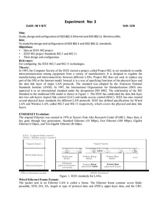
  • 1. Experiment No: 3 CLASS : BE E &TC SUB : CCN Title: Study,designandconfigurationof IEEE802.3 EthernetandIEEE 802.11 WirelessLANs. Aim: To studythe designandconfigurationof IEEE 802.3 and IEEE 802.11 standards. Objectives: • Idea on IEEE 802 project. • IEEE 802 project Standards 802.3 and 802.11. • Their design and configuration. Relevance: For configuring the IEEE 802.3 and 802.11 technologies. Theory: In 1985, the Computer Society of the IEEE started a project, called Project 802, to set standards to enable intercommunication among equipment from a variety of manufacturers. It is designed to regulate the manufacturing and interconnectivity between different LANs. Project 802 does not seek to replace any part of the OSI or the Internet model. Instead, it is a way of specifying functions of the physical layer and the data link layer of major LAN protocols. The standard was adopted by the American National Standards Institute (ANSI). In 1987, the International Organization for Standardization (ISO) also approved it as an international standard under the designation ISO 8802. The relationship of the 802 Standard to the traditional OSI model is shown in Figure 1. The IEEE has subdivided the data link layer into two sub-layers: logical link control (LLC) and media access control (MAC). IEEE has also created several physical layer standards for different LAN protocols. IEEE has defined specifications for Wired LAN and Wireless LAN, called 802.3 and 802.11 respectively, which covers the physical and data link layers. ETHERNET Evolution: The original Ethernet was created in 1976 at Xerox's Palo Alto Research Center (PARC). Since then, it has gone through four generations: Standard Ethernet (10 Mbps), Fast Ethernet (100 Mbps), Gigabit Ethernet (l Gbps), and Ten-Gigabit Ethernet (l0 Gbps). Figure 1. IEEE standards for LANs Wired Ethernet Frame Format: The packet sent in an Ethernet LAN is called a frame. The Ethernet frame contains seven fields: preamble, SFD, DA, SA, length or type of protocol data unit (PDU), upper-layer data, and the CRC.
  • 2. Ethernet does not provide any mechanism for acknowledging received frames, making it what is known as an unreliable medium. Acknowledgments must be implemented at the higher layers. The frame format of the MAC frame is shown in Figure 2. Figure 2. 802.3 MAC Frame Preamble:The firstfieldof the 802.3 frame contains7 bytes(56 bits) of alternatingOsand1s that alerts the receivingsystemtothe comingframe andenablesittosynchronize itsinputtiming.The pattern providesonlyanalertanda timingpulse.The 56-bitpatternallowsthe stationstomisssome bitsatthe beginningof the frame.The preamble isactuallyaddedatthe physical layerandisnot (formally) partof the frame. Start frame delimiter(SFD):The secondfield(l byte:10101011) signalsthe beginningof the frame.The SFD warnsthe stationor stationsthat thisisthe last chance for synchronization.The last2 bitsis 11 and alertsthe receiverthatthe nextfieldisthe destinationaddress. Destinationaddress (DA):The DA fieldis6bytesand containsthe physical addressof the destination stationor stationstoreceive the packet. Source address(SA): The SA fieldisalso6 bytesandcontainsthe physical addressof the senderof the packet. Length or type: Thisfieldisdefinedasatype field orlengthfield.The original Ethernetusedthisfieldas the type fieldtodefine the upper-layerprotocol usingthe MACframe.The IEEE standarduseditas the lengthfieldtodefine the numberof bytesinthe data field.Bothusesare commontoday. Data: Thisfieldcarriesdataencapsulatedfromthe upper-layerprotocols.Itisa minimumof 46 and a maximumof 1500 bytes. CRC: The lastfieldcontainserrordetectioninformation,inthiscase a CRC-32. Wireless Ethernet Frame Format: The MAC layer frame consists of nine fields, as shown in Figure 3. FC D Address1 Address 2 Address 3 SC Address 4 Frame Body FCS 2bytes 2bytes 6bytes 6bytes 6bytes 2bytes 6bytes 0-2312 bytes 4bytes Figure 2. Frame Format Frame control (FC): The FC field is 2 bytes long and defines the type of frame and some control information.Table 1describesthe subfields. Field Explanation
  • 3. Version Current version is 0 Type Type of information: management (00), control (01), or data (10) Subtype Subtype of each type (RTS, CTS, ATS) To DS Defined later From DS Defined later More flag When set to 1, means more fragments Retry When set to 1, means retransmitted frame Pwr mgt When set to 1, means station is in power management mode More data When set to 1, means station has more data to send WEP Wired equivalent privacy (encryption implemented) Rsvd Reserved Table 1. Sub fields in FC Field. D: Inall frame typesexceptone,thisfielddefinesthe durationof the transmissionthatisusedtoset the value of NAY.In one control frame,thisfielddefinesthe IDof the frame. Addresses:There are four addressfields,each6byteslong.The meaningof eachaddressfielddepends on the value of the To DS and From DS subfields. Sequence control:This fielddefinesthe sequence numberof the frame tobe usedinflow control. Frame body: Thisfield,whichcanbe between0and2312 bytes,containsinformationbasedonthe type and the subtype definedinthe FCfield. FCS: The FCS fieldis4 byteslongandcontainsa CRC-32 error detectionsequence. Frame Types A wirelessLAN definedbyIEEE802.11 has three categoriesof frames:managementframes,control frames,anddata frames. ManagementFrames: Managementframesare usedforthe initial communicationbetweenstations and accesspoints. Control Frames:Control framesare usedforaccessingthe channel andacknowledging frames. Data Frames: Data framesare usedforcarryingdata and control information. AddressingMechanism: The IEEE 802.11 addressingmechanismspecifiesfourcases,definedbythe value of the twoflagsinthe FC field,ToDSand From DS. Each flagcan be either0or I,resultinginfourdifferentsituations.The interpretationof the fouraddresses(addressItoaddress4) in the MAC frame dependsonthe value of these flags,asshowninTable 2. To DS From DS Address1 Address2 Address3 Address4 0 0 Destination Source BSS ID N/A 0 1 Destination Sending AP Source N/A 1 0 Receiving AP Source Destination N/A 1 1 Receiving AP Sending AP Destination Source Table 2. Addresses Note that address1 isalwaysthe addressof the nextdevice.Address2isalwaysthe addressof the previousdevice.Address3isthe addressof the final destinationstationif itisnotdefinedbyaddressI. Address4 isthe addressof the original source stationif itisnot the same as address2. Case 1: 00 Inthiscase, To DS = 0 and From DS = O. Thismeansthat the frame is notgoingto a distributionsystem(ToDS= 0) andis notcomingfrom a distributionsystem(FromDS=0). The frame is goingfromone stationin a BSS to anotherwithoutpassingthroughthe distributionsystem.The ACK frame shouldbe sentto the original sender.
  • 4. Case 2: 01 Inthiscase, To DS = 0 and From DS = 1. Thismeansthat the frame iscomingfrom a distributionsystem(From DS= 1). The frame is comingfroman APand goingto a station.The ACK shouldbe sentto the AP.Note that address3 containsthe original senderof the frame (inanotherBSS). Case 3: 10 Inthiscase, To DS =1 and FromDS =O. This meansthatthe frame isgoingto a distribution system(ToDS = 1). The frame is goingfroma stationto an AP.The ACKissentto the original station. Note that address3 containsthe final destinationof the frame (inanotherBSS). Case 4:11 In thiscase,To DS =1 andFrom DS =1. Thus isthe case inwhichthe distributionsystemisalso wireless.The frame isgoingfromone APto anotherAPin a wirelessdistributionsystem.We donot needtodefine addressesif the distributionsystemisawiredLAN because the frame inthese caseshas the format of a wiredLAN frame (Ethernet,forexample).Here,we needfouraddressestodefine the original sender,the finaldestination,andtwointermediate APs.The addressesare showninfigure 3. Figure 3. Addressing Mechanisms. Configuration: Figure 4. Static IP Configuration of Ethernet LAN (Wired and Wireless). Conclusion:Thuswe understandthe IEEE 802.3 and 802.11 standardsfor WiredandWirelessLANs.