SlideShare une entreprise Scribd logo
1  sur  44
Télécharger pour lire hors ligne
DEMCO Butterfly Valves
Quality design and rugged dependability in meeting the rigorous requirements of
industrial, oilfield and drilling applications
1
DEMCO BUTTERFLY VALVES
Introduction........................................................................................... 	2
Features and Benefits ............................................................................ 	3
Styles and Accessories............................................................................ 	6
Series NE-C, NE-I, NE-D, NEI-T................................................................ 	9
Series NF-C............................................................................................ 	10
Base Part Numbers and Weights............................................................ 	12
Marine Series......................................................................................... 	13
Component Parts List............................................................................. 	14
Dimensional Data (Valves)...................................................................... 	16
Handles................................................................................................. 	22
Worm Gear Operators........................................................................... 	23
Stem Extensions..................................................................................... 	25
General Technical Information................................................................ 	26
Torque Data........................................................................................... 	31
Standard Material Data.......................................................................... 	32
Material Selection Guide........................................................................ 	33
Services for Valves and Actuation........................................................... 	39
Trademark Information.......................................................................... 	40
Table of Contents
2
DEMCO Butterfly Valves
Cameron is a leading provider of valves, valve automation, and measurement
systems to the oil and gas industry. Our products are primarily used to control, direct
and measure the flow of oil and gas as it is moved to refineries, petrochemical
plants, and industrial centers for processing.
We provide valve products that are sold through distributor networks worldwide for
use in both oil and gas and industrial applications and include such widely
recognized brands as DEMCO®
, NAVCO®
, NEWCO®
, NUTRON®
, THORNHILL
CRAVER®
, TECHNO™
, TOM WHEATLEY®
, WHEATLEY®
, and WKM®
.
Cameron’s DEMCO butterfly valves are the valves of choice, engineered and proven
for drilling and production industries. Designed for dependable, heavy-duty
performance in abrasive and corrosive service conditions, DEMCO butterfly valves are
commonly selected for a number of oilfield applications.
Oklahoma City,
Okla., USA
3
FEATURES AND BENEFITS
As one of the most durable resilient-seated butterfly valves in
the industry, Cameron’s DEMCO butterfly valve excels in a
variety of applications.
Cast in both wafer and tapped lug patterns in a variety of
material choices, DEMCO butterfly valves feature a one-piece
body for reduced weight and increased strength.
The unique stem hole design in the disc ensures the dry stem
journal, and the hard-backed seat allows ease of installation,
reliable operation and in-field repairability without special
tools. DEMCO butterfly valves are available in sizes 2” to 36”
(50 mm to 900 mm).
Engineered for long-term, reduced-maintenance
performance, DEMCO butterfly valves are commonly
selected for a variety of applications in the following
industries:
•	 Chemical and petrochemical
•	Agriculture
•	 Oil and gas drilling and production
•	 Food and beverage
•	 Water and waste water
•	 Cooling towers (HVAC)
•	Power
•	 Mining and materials
•	 Dry bulk handling
•	 Marine and government
Bi-Directional Sealing
Cameron’s DEMCO butterfly valve provides bi-directional
sealing at full-rated pressure with identical flow from either
direction.
Integral Flange Seal
An integral flange seal molded into the edge of the seat
accommodates ASME weld neck, slip-on, threaded, socket
and stub end type C flanges.
ASME Class 150 Rating
With a body rating of ASME Class 150 (285 psi non-shock),
the wafer body diameters are designed to self-center in the
ASME Class 150 flange pattern.
Flatted Double D
Upper Stem
Large Flange Top for
Ease of Power
Automation
Positive Stem Retention
for Blowout-Proof
Stems
MSS-SP-25 Marking is
Standard
Triple Stem Seal
High-Flow Disc
Bronze Bearings
Positively Oriented Disc
Hard-Backed Cartridge Seat
Wafer Style Shown
One-Piece Body
4
Multiple Pressure Ratings
Three drop-tight pressure ratings are offered for 2” to 12” (50 mm to 300 mm) sizes. The standard shut-off pressure rating is
200 psi, but 285 and 50 psi shut-off ratings are also available. A throttling 0 psi-rated valve is available where drop-tight closure
is not required and minimal torque is desired. Both the 50 psi and throttling ratings allow for smaller actuators, which can
significantly reduce overall installation cost in automated applications. The 14” to 36” (350 mm to 900 mm) size valves are
available in 150 and 50 psi drop-tight shut-off ratings, as well as throttling.
A. Dry Stem Journal Reduces Potential for
Leakage
The DEMCO valve’s disc is uniquely designed with a
continuous annular-raised band around the stem hole and
disc edge, which presses into the seat flat at every angular
position.
The resilient seat presses back with a higher force than the
line pressure, preventing leakage to the stem. In addition,
two O-ring ribs are provided in the seat stem bore, creating a
triple stem seal. In competitive stem seal designs with boot
seats, a seal is accomplished by an interference squeezing on
the stem or an O-ring in the stem journal. The potential for
leakage behind the seat is high for this competitive design.
As the disc wipes the seat, elongation of the stem seal area
allows leakage to collect behind the seat. This condition is
reduced by the DEMCO valve’s dry stem journal and hard-
backed seat.
B. Hard-Backed Cartridge Seat
The DEMCO valve’s cartridge seat is constructed by
permanently bonding a resilient elastomer to a rigid backing
ring. In addition to superior sealing integrity, this design:
•	Makes valve installation easier because no special
precautions are required for disc position. This is
especially advantageous when installing valves with
fail-closed actuators.
•	Reduces high torque and premature failure caused by
elastomer distortion, as found in other non-rigid seat
designs.
•	Simplifies seat replacement because the seat is slip-fitted
into the body with no need for special tools.
Hard-Backed
Seat
BA
FEATURES AND BENEFITS (CONT.)
5
C. Positively Oriented Disc
The rectangular drive ensures the proper orientation of the
stem disc connection. In 2” to 24” (50 mm to 600 mm) size
valves, the disc is permitted to float on the stem to center in
the valve seat. This design enhances drop-tight sealing and
prolongs service life.
Sizes
2” to 36” (50 mm to 900 mm)
Body Type and Style Designations
Long-Neck NE-C and NF-C: 2” to 36” (50 mm to
900 mm) wafer/lug, 36” (900 mm)
Short-Neck NE-I and NE-I Sanitary: 2” to 12“ (50
mm to 300 mm) wafer/lug
NE-IT Teflon: 2” to 10” (50 mm to 250 mm)
wafer/lug
NE-D: 2” to 12” (50 mm to 300 mm) wafer
Marine: 2” to 24” (50 mm to 600 mm) wafer/lug
Pressure Rating
2“ to 12” (50 mm to 300 mm):
0 (throttling); 50, 200 and 285 psi
NEI-T: 2” to 10” (50 mm to 250 mm): 150 psi
14” to 36” (350 mm to 900 mm): 0, 50 and 150 psi
Operating Temperatures
-30º F to 300º F (-34º C to 204º C), depending on
seat material selection and application (see page 32)
Standard Material Options
Bodies: Iron, steel, stainless steel and bronze
Discs: Nickel-plated ductile iron, bronze and stainless
steel
Stems: 416 and 316 stainless steel
Seats: Buna-N, EPDM, FKM and Neoprene
*Many more options available (consult Cameron or
see pages 9, 10 and 11 on how to order).
D. End-of-Line Service
Lug body valves may be used in end-of-line service with
downstream piping removed. Only weld-neck or socket
flanges can be used for this service. Since upstream pressure
is excluded between the flange and the seat face by the
DEMCO flange seal design, there is no effective force to slide
the seat downstream. DEMCO 2” to 12” (50 mm to 300
mm) lug butterfly valves are suitable for liquid service up to
200 psi with downstream piping removed at 150 psi for 14”
to 36” (350 mm to 900 mm) valves.
Lug body valves are recommended for isolation of pumps,
control devices or other system components, which may
need to be removed for repair or replacement. Lug valves
also are suitable for installation at points from which piping
expansion may proceed. Such valves normally are blanked
with blind flanges to protect the exposed seats until new
piping is attached.
Upstream Disc
Disc
Stem
D
C
SPECIFICATIONS
6
STYLES AND ACCESSORIES
The DEMCO butterfly valve comes in a variety of styles to suit a range of applications. In addition, a variety of quality accessories
are available to further enhance its suitability to the application.
Series NE-C
Sizes 2” to 12” (50 mm to 300 mm) are available in both
wafer and lug styles. This series is a general purpose valve
with a neck length designed to provide full clearance for the
valve top over 2” of insulation on ASME Class 150 pipe
flanges.
Series NE-I
Sizes 2” to 12” (50 mm to 300 mm) are suited for a range
of applications in many industries, including food and
beverage utilities and process flowlines. This short neck
design is offered in a variety of body materials. The valves
are designed for installation between ASME Class 125 and
150 flanges.
Series NE-D
The valves in this series can be made in sizes 2” to 12” (50
mm to 300 mm). The Series NE-D valve is a short-neck valve
with body notches to fit popular, lightweight flange
patterns, making it ideal for both the bulk material handling
and the transportation industries. Valves also will center in
ASME Class 125 and 150 flanges.
Series NF-C
Sizes 14” to 36” (350 mm to 900 mm) are available in both
wafer and lug styles. The wafer body has two drilled locator
lugs at the top and bottom for ASME Class 150 flanges.
Bronze bearings are installed on both stems for reduced
operating torque.
7
Series NE-I Sanitary
This series comes in sizes 2” to 12” (50 mm to 300 mm). It
is similar to the Series NE-I valve, but is exclusively designed
to meet the rigorous requirements of sanitary service in the
food and beverage industry. The body is available in bronze,
stainless steel, aluminum or electroless nickel-coated ductile
iron.
FDA-approved materials are used for all wetted parts.
Handle parts are bronze and stainless steel, permitting
caustic washdown.
Other benefits:
•	The DEMCO dry journal stem seal system ensures sanitary
butterfly valve construction.
•	Drilled passageways, a design originated by the DEMCO
brand, vent the entire interior of the disc. No closed
chamber is provided for the culture of undesirable
organisms.
•	Discs are produced from smooth and non-porous
investment castings. Stem bosses are reduced for
increased flow.
•	The mating flange contacts and compresses the
projecting inner surface of the resilient seat to form a
smooth and uninterrupted flow way. This positive seal
between the innermost contact of the seat and flange
ensures aseptic conditions after a piping flush.
Sanitary Features
Series NEI-T Teflon
Because of the inert, aseptic, non-stick character of Teflon®
,
the DEMCO NEI-T Teflon-lined butterfly valve is ideal for
clean lines in food and beverage plants. The Teflon seat
consists of a virgin Teflon liner overlaid and bonded to an
elastomer EPDM cushion, which provides resilience for
sealing. The Teflon liner extends over the seat faces,
completely covering and sealing the resilient material from
contact with line fluids.
Marine
DEMCO marine butterfly valves are available in the NE-C lug,
NE-I lug and wafer, and NE-D wafer styles, and conform to:
•	 Title 46 of the Code of Federal Regulations
•	Part 56 of the US Coast Guard’s Marine Engineering
Regulations
•	The American Bureau of Shipping Standard, including
tagging per MSS-SP-25 and testing per MSS-SP-67
Stem Seal
Vented
Design
High-Flow
Discs
Trap-Free
Flow Way
8
A. Actuators
Consult Cameron or visit www.c-a-m.com/valveautomation
for actuation options.
B. Handles and Stem Extensions
There are three basic handle designs that are compatible
with any 2” to 12” (50 mm to 300 mm) valve: ten-position
locking, two-position locking and memory stop. Memory-
stop handles provide throttling, which is infinitely adjustable
and can be set by a lock nut with a memory-stop setting
(adjustable open stop). Handles are available in basic trim,
corrosion-resistant trim and sanitary trim. Stem extensions
are fabricated from carbon steel parts and contained in a
tubular housing. Gaskets and O-rings seal the stem
extension at the top and bottom. These extensions are
fabricated to specified lengths.
C. Gear Operators
DEMCO weatherproof gear operators are offered with a
choice of handwheel, chainwheel or square nuts. The worm
gear has either self-locking set screws to control open and
closed positioning or an optional adjustable memory-stop
for balance return to a preset open position after closing.
A. DEMCO NE-C Wafer
B. Stem Extension with
Handle on Series NE-I
Butterfly Valve
C. Gear-Operated
STYLES AND ACCESSORIES (CONT.)
9
SERIES NE-C, NE-I, NE-D, NEI-T
2” to 12” (50 mm to 300 mm)
Key No. Qty. Description Material
1 1 Body *
2 1 Seat *
3 1 Disc *
4 1 Upper Stem *
6 1 Lower Stem *
7 2 Spring Pin Stainless Steel
14 1 Retainer Stainless Steel
22 1 Top O-ring Buna-N
23 • Stem O-ring Buna-N
24 2 Bearing Bronze
*	 See How to Order for material choices/styles.
	 Complete material specs on page 32.
•	 Four required for throttling valves only.
HOW TO ORDER
(Example: 6” (150 mm) NE-C, 200 psi, Wafer, Standard Trim
with Handle – 22124-1215311)
*	 Standard coating is green enamel; other coatings are available on request.
**	 17-4 PH SS for 8” to 12” (200 mm to 300 mm) upper stem only.
***	 Except 17-4 PH upper 8” and 10” (200 mm and 250 mm).
1	 200 psi only.
2	 Except 285 psi.
3	Polished – ground to #4 dairy finish; tumbled – vibratory finish to remove as cast surface; unpolished – as cast surface.
4	When these options are used with NE-I sanitary butterfly valves, handles will be bronze with stainless steel (SS) parts and fasteners.
5	 Gear operator recommended for 8” to 12” (200 mm to 300 mm) sizes in all series.
6	 See material trademark note on page 40.
7	 Other seat options available (consult Cameron).
Handle
10 Position Lkg. 14
Throttling Mem./
Stop
24
Square Nut 5
2-Position Lkg. 64
10-Position Sanitary
(NEI-T Only)
8
None 9
10-Position Lkg.
Corrosion-Resistant
K
2-Position Lkg.
Corrosion-Resistant
L
Throttling Mem./
Stop Corrosion-
Resistant
M
Gear Operators5
Handwheel A
Crank 2” to 12” (50
mm to 300 mm)
B
Chainwheel C
Square Nut D
Bare Shaft E
NE-C, NE-I and NE-D7
Buna-N 31
Black Neoprene 32
Hypalon6
33
FKM 34
Peroxide-Cured, EPDM 35
Natural Rubber 36
White Neoprene 37
ETM-30230 01
Fluorosteam 02
Peroxide-Cured
Food Grade, EPDM
03
Peroxide-Cured, Buna-N 04
Sulfur-Cured
Food Grade, EPDM
05
NEI-T
Peroxide-Cured,EPDM/Teflon6
35
Sulfur-Cured, EPDM/Teflon6
05
NE-I Sanitary
All Seats Food Grade
Black Neoprene 32
FKM 34
EPDM 35
White Neoprene 37
Sulfur-Cured, EPDM 05
NE-C, NE-I and NE-D
316 SS 2
Monel6
3
Aluminum
Bronze
4
Ductile Iron,
Nickel-Plated
5
PVF-Coated
Ductile Iron1 6
Alloy 202
7
Hastelloy “C”6
8
NEI-T and
NE-I Sanitary
316 SS Polished3
2
316 SS Tumbled3
5
Alloy 20
(NEI-T Only)
7
Hastelloy “C”6
(NEI-T Only)
8
316 SS Unpolished3
9
NE-C, NE-I
and NE-D
416 SS 1
316 SS** 2
Monel6
3
NEI-T
316 SS
Vented***
2
316 SS
Solid***
9
NEI-Sanitary
316 SS*** 2
NE-C (Long-Neck)
Ductile Iron (Lug) 1
Cast Iron (Wafer) 2
NE-I and NE-I Sanitary
Ductile Iron (NE-I,Wafer Only) 1
Aluminum Bronze 3
Carbon Steel (NE-I Only) 4
Aluminum (NE-I,Wafer Only) 5
ENC-Coated Ductile Iron 6
Stainless Steel 8
NE-D
Ductile Iron 1
NEI-T
Ductile Iron
Wafer – Short-Neck
Lug – Long-Neck
1
Gray Iron (Long-Neck Wafer) 2
Aluminum Bronze 3
Carbon Steel 4
Aluminum (Wafer Only) 5
Stainless Steel 8
NE-C/NE-I/NEI-T
Wafer 1
Lug 5
NE-D
Wafer 1
Based on
valve series
and shut-off
pressure.
See page 12.
X X X X X
Base Part Number
-
X X X X XX X
Body
Configuration
Body Material*
Stem
Material
Disc
Material
Seat Elastomer Actuation
22
24
4
14
24
1
7
23
2
3
1
1
1
1
6
723
Series NE-C
Wafer
Series NE-I
Wafer
Series NE-I
Lug
Series NE-D
Wafer
Series NE-C
Lug
10
SERIES NF-C
14” to 24” (350 mm to 600 mm)
Key No. Qty. Description Material
1 1 Body *
2 1 Seat *
3 1 Disc *
4 1 Upper Stem *
6 1 Lower Stem *
7 2 Spring Pin Stainless Steel
14 1 Retainer (Spacer) + Stainless Steel
22 1 Top O-ring Buna-N
23 • Stem O-ring Buna-N
24 2 Bearing Bronze
HOW TO ORDER
(Example: 18” (450 mm) NF-C, 150 psi Lug, SS Trim, Buna-N Seat, WGO – 23822-512231A)
None 9
Gear Operators
Handwheel A
Chainwheel C
Square Nut D
Bare Shaft E
Buna-N 31
Black Neoprene 32
Hypalon6
33
FKM 34
EPDM 35
316 SS 2
Monel2
3
Aluminum
Bronze
4
Nickel-Plated Iron 5
PVF-Coated
Ductile Iron1 6
416 SS 1
316 SS 2
Monel2
3
Ductile Iron (Lug) 1
Cast Iron (Wafer) 2
Aluminum Bronze (Lug) 3
Steel (Lug) 4
Stainless Steel (Lug) 8
Wafer 1
Lug 5
X X X X X
Base Part Number
-
X X X X XX X
Body
Configuration
Body Material*
Stem
Material
Disc
Material
Seat Elastomer Actuation
Based on
valve series
and shut-off
pressure.
See page 12.
*	 See How to Order for material choices/styles.
	 Complete material specs are on page 32.
•	 Four required for throttling valves only.
+	 14” to 20” (350 mm to 500 mm) spacer.
*	 Standard coating is green enamel; other coatings are available on request.
1	 150 psi only.
2	 See material trademark note on page 40.
1
1
6
7
2
23
3
25
23
23
23
24
4
7
14
24
11
SERIES NF-C
30“ and 36” (750 mm and 900 mm)
Key No. Qty. Description Material
1 1 Body *
2 1 Seat – Hard-Backed *
3 1 Disc *
4 1 Upper Stem *
6 1 Lower Stem *
7 2 Disc Screw 18-8 SS
8 1 Key Stainless Steel
9 2 O-ring Buna-N
14 1 Spacer Steel
24 2 Upper Bearing Bronze
25 1 Lower Bearing Bronze
26 1 Thrust Collar Bronze
27 1 Set Screw 18-8 SS
28 1 Cap Ductile Iron
29 4 Screw Carbon Steel
30 4 Lockwasher Carbon Steel
*	 See How to Order for material choices/styles.
	 Complete material specs on page 32.
HOW TO ORDER
(Example: 36 “ (900 mm), 150 psi, Bronze Disc, EPDM Seat with Gear Op. – 24357-111435A)
*	 Standard coating is green enamel; other coatings are available on request.
1	 See material trademark note on page 40.
Handwheel A
Chainwheel C
Square Nut D
Bare Shaft E
Buna-N 31
FKM 34
EPDM 35
316 SS 2
Monel1
3
Aluminum
Bronze
4
Ductile Iron,	 Nickel-
Plated
5
416 SS 1
316 SS 2
Monel1
3
Ductile Iron
(Wafer or Lug)
1Wafer 1
Lug 5
See page 12.
X X X X X
Base Part Number
-
X X X X XX X
Body
Configuration
Body Material*
Stem
Material
Disc
Material
Seat Elastomer Actuation
4
1
2
3
8
24
14
24
9
27
7
6
25
26
28 29 30
12
BASE PART NUMBERS AND WEIGHTS
Description
in. 2 2-1/2 3 4 5 6 8 10 12
(mm) (50) (65) (80) (100) (125) (150) (200) (250) (300)
200 psi 22119 22120 22121 22122 22123 22124 22125 22126 22127
285 psi 22225 22226 22227 22228 22229 22230 22231 22232 22233
50 psi 22234 22235 22236 22237 22238 22239 22240 22241 22242
Throttling 22243 22244 22245 22246 22247 22248 22249 22250 22251
Weight
(lb – bare stem)
Wafer 5.8 7.0 7.7 11.4 14.7 17.6 28.5 47.9 71.0
Lug 8.0 9.9 10.7 17.0 24.5 28.5 43.5 65.9 98.5
Description
in. 2 2-1/2 3 4 5 6 8 10 12
(mm) (50) (65) (80) (100) (125) (150) (200) (250) (300)
200 psi 22128 22129 22130 22131 22132 22133 22134 22135 22136
285 psi 22252 22253 22254 22255 22256 22257 22258 22259 22260
50 psi 22261 22262 22263 22264 22265 22266 22267 22268 22269
Throttling 22270 22271 22272 22273 22274 22275 22276 22277 22278
Weight
(lb – bare stem)
Wafer
Iron, Steel, SS 4.9 6.4 6.9 10.2 13.7 16.4 28.4 44.8 66.8
Bronze 4.7 6.2 6.7 9.9 13.4 16.0 28.0 44.3 66.3
Aluminum 2.8 3.4 4.1 5.9 8.7 10.8 18.2 30.4 47.2
(lb – bare stem)
Lug
Bronze 6.8 8.7 9.5 15.7 23.1 27.0 42.0 64.4 96.8
Steel, SS 7.0 8.9 9.7 16.0 23.5 27.5 42.5 64.9 97.5
	
Description
in. 2 2-1/2 3 4 6 8 10 12
(mm) (50) (65) (80) (100) (150) (200) (250) (300)
200 psi 23150 23151 23152 23153 23154 23155 23156 23157
Weight See chart above: NE-I, 2” to 12” (50 mm to 300 mm)
Description in. 2 2-1/2 3 4 5 6 8 10 12
(mm) (50) (65) (80) (100) (125) (150) (200) (250) (300)
200 psi 22181 22129 25093 22183 22184 22185 22134 22186 22136
285 psi 22279 22253 25135 22281 22282 22283 22258 22284 22260
50 psi 22285 22262 25132 22287 22288 22289 22267 22290 22269
Throttling 22291 22271 25136 22293 22294 22295 22276 22296 22278
Weight (lb – bare stem) Wafer 4.9 6.4 6.9 10.2 13.7 16.4 28.4 44.8 66.8
Description
in. 2 2-1/2 3 4 6 8 10
(mm) (50) (65) (80) (100) (150) (200) (250)
150 psi 24680 24681 24682 24683 24684 24685 24686
Weight
(lb – bare stem)
Wafer**
Iron, Steel, SS 4.9 6.4 6.9 10.2 16.4 28.4 44.8
Bronze 4.7 6.2 6.7 9.9 16.0 28.0 44.3
Aluminum 2.8 3.4 4.1 5.9 10.8 18.2 30.4
(lb – bare stem)
Lug**
Bronze 6.8 8.7 9.5 15.7 27.0 42.0 64.4
Steel, SS 7.0 8.9 9.7 16.0 27.5 42.5 64.9
Description
in. 14 16 18 20 24
(mm) (350) (400) (450) (500) (600)
150 psi 23820 23821 23822 23823 23824
50 psi 24440 24441 24442 24443 24444
Throttling 24445 24446 24447 24448 24449
Weight
(lb – bare stem)
Wafer 102 166 214 257 401
Lug 116 203 239 332 535
*	 Gear operator recommended for 8” to 12” (200 mm to 300 mm) sizes.
**	 See NE-C chart above for weights of long-neck wafer and lug valves.
Marine valves: consult Cameron for data sheets B-255, B-256 and B-258.
Description
in. 30 36
(mm) (750) (900)
150 psi 24141 24357
50 psi 24924 25061
Weight Wafer 935 1500
Lug 1050 2020
Series NE-C, 2” to 12“ (50 mm to 300 mm)*
Series NE-I, 2” to 12“ (50 mm to 300 mm)*
Series NE-I, Sanitary 2” to 12“ (50 mm to 300 mm)*
Series NE-D, 2” to 12“ (50 mm to 300 mm)*
Series NEI-T, 2” to 10“ (50 mm to 250 mm)*
Series NF-C, 14” to 24“ (350 mm to 600 mm) Series NF-C, 30” to 36“ (750 mm to 900 mm)
13
DEMCO marine butterfly valves meet all the requirements of US Coast Guard’s Marine Engineering Regulations as outlined in
Title 46 of the Code of Federal Regulations, Part 56 and The American Bureau of Shipping Standard, including tagging per
MSS-SP-25 and testing per MSS-SP-67. All valves are shell tested at 1-1/2 times rated working pressure and seat tested at rated
working pressure.
Description
in. 2 2-1/2 3 4 5 6 8 10 12
(mm) (50) (65) (80) (100) (125) (150) (200) (250) (300)
200 psi 22923 22924 22925 22926 22927 22928 22929 22930 22931
50 psi 22932 22933 22934 22935 22936 22937 22938 22939 22940
285 psi 22914 22915 22916 22917 22918 22919 22920 22921 22922
Weight
(lb – bare stem)
NE-C Long-Neck Body
Wafer Gray Iron 5.8 7.0 7.7 11.4 14.7 17.6 28.5 47.9 71.0
Lug Ductile Iron 8.0 9.9 10.7 17.0 24.5 28.5 43.5 65.9 98.5
NE-I Short-Neck Body
Wafer Iron, Steel, SS 4.9 6.4 6.9 10.2 13.7 16.4 28.4 44.8 66.8
Bronze 4.7 6.2 6.7 9.9 13.4 16.0 28.0 44.3 66.3
Lug Bronze 6.8 8.7 9.5 15.7 23.1 27.0 42.0 64.4 96.8
SS, Steel 7.0 8.9 9.7 16.0 23.5 27.5 42.5 64.9 97.5
Description
in. 14 16 18 20 24 30 36
(mm) (350) (400) (450) (500) (600) (750) (900)
150 psi 24611 24612 24613 24614 24615 2227182 2227183
50 psi 24653 24654 24655 24656 24657 2227184 2227185
Weight
(lb – bare stem)
NF-C Long-Neck Body
Lug Ductile Iron 116 203 239 332 535 1050 2020
Bronze 113 199 235 325 525 N/A N/A
HOW TO ORDER
(Example: 6” (150 mm) 200 psi Wafer, Standard Trim with 10-Position Handle – 22928-1114311)
10-Position Handle 1
Throttling
Memory Stop
2
2-Position Locking 6
Worm Gear
Handwheel
A
Buna-N* 31
Black Neoprene 32
Hypalon1
33
FKM 34
EPDM* 35
Natural Rubber 36
White Neoprene 37
Stainless Steel 2
Monel1
3
Aluminum
Bronze*
4
416 SS* 1
316 SS 2
Monel1
3
Ductile Iron 1
Aluminum Bronze 3
Carbon Steel 4
Stainless Steel 8
Wafer 1
Lug 5
X X X X X
Base Part Number
-
X X X X XX X
Body
Configuration
Body Material*
Stem
Material
Disc
Material
Seat
Material
Actuation
Base part no.
of valve
shown above.
*	 Standard base trim options.
**	 Wafer 2” to 12” (50 mm to 300 mm) only.
	 Lug 2” to 36” (50 mm to 900 mm).
Note: 30” and 36” (750 mm to 900 mm) available with ductile iron lug body only.
1	 See material trademark note on page 40.
MARINE SERIES
Marine Series, 2” to 36“ (50 mm to 900 mm)
14
COMPONENT PARTS LIST:
SERIES NE-C, NE-I, NE-D
Key
Description
2” 2-1/2” 3” 4” 5” 6” 8” 10” 12”
No. (50 mm) (65 mm) (80 mm) (100 mm) (125 mm) (150 mm) (200 mm) (250 mm) (300 mm)
1 Body NE-C Wafer
Options
22137-012 22138-012 22139-012 22140-012 22141-012 22142-012 22143-012 22144-012 22145-012
ASTM A48 Gray Iron -012
NE-C Lug 21986-051 21987-051 21988-051 21989-051 21990-051 21991-051 21992-051 21993-051 21994-051
Options ASTM A395 Ductile Iron -051
NE-I Wafer 22681-01x 22682-01x 22683-01x 22684-01x 22685-01x 22686-01x 22687-01x 22688-01x 22689-01x
Options ASTM A395 Ductile Iron -011, ASTM B148 Aluminum Bronze -013, ASTM A216 WCB Steel -014,
ASTM B179 Aluminum -015, DI/ENC -016, ASTM A351 SS -018
NE-I Lug 22695-05x 22696-05x 22697-05x 22698-05x 22699-05x 22700-05x 22701-05x 22702-05x 22703-05x
Options ASTM B148 Aluminum Bronze -053, ASTM A216 WCB Steel -054, ASTM A351 SS -058
NE-D Wafer 22187-021 22682-011 20594-021 22189-021 22190-021 22191-021 22687-011 22192-021 22689-011
Options ASTM A395 Ductile Iron -0x1
2 Seat 1786-xxx 1788-xxx 1790-xxx6
1792-xxx 1794-xxx 1002-xxx 1798-xxx 1815-xxx 1817-xxx
Options Buna-N -031, Black Neoprene -032, Hypalon7
-033, FKM -034, EPDM1
-135, Natural Rubber -036
White Neoprene -037, Peroxide-Cured Buna-N -231, Fluorosteam -244, ETM-30230 -3313” NE-D Seat (See Below6
)
3 Disc 200 psi 22045-0xx 22046-0xx 22047-0xx 22048-0xx 22049-0xx 22050-0xx 22051-0xx 22052-0xx 22053-0xx
285 psi 22196-0xx 22197-0xx 22198-0xx 22199-0xx 22200-0xx 22201-0xx 22202-0xx 22203-0xx 22204-0xx
50 psi 22205-0xx 22206-0xx 22207-0xx 22208-0xx 22209-0xx 22210-0xx 22211-0xx 22212-0xx 22213-0xx
Throttling 22214-0xx 22215-0xx 22216-0xx 22217-0xx 22218-0xx 22219-0xx 22220-0xx 22221-0xx 22222-0xx
Options 316 SS -002, Monel -003, Nickel-Plated Ductile Iron -005, Alloy 202
-007, Hastelloy C7
-008, Aluminum Bronze3
-014
PVF-Coated, 200 psi 22714-001 22715-001 22716-001 22717-001 22718-001 22719-001 22720-001 22721-001 22722-001
4 Upper Stem NE-C 22066-00x 22067-00x 22068-00x 22069-00x 22070-00x 22071-00x 22072-00x
NE-I 22073-00x 22074-00x 22075-00x 22076-00x 22077-00x 22078-00x 22079-00x
NE-D 22073-00x 22074-00x 22193-00x 22194-00x 22195-00x 22077-00x 22078-00x 22079-00x
Upper Stem NE-C 22334-00x 22335-00x 22336-00x 22337-00x 22338-00x 22339-00x 22340-00x
-Utility Top NE-I 22341-00x 22342-00x 22343-00x 22344-00x 22345-00x 22346-00x 22347-00x
6 Lower Stem 22080-00x 22081-00x 22082-00x 22083-00x 22084-00x 22085-00x 22086-00x
Stem Material Options 416 SS -001, 316 SS4
-002, Monel7
-003
7 Spring Pin (2) 302 SS 5448-18720 5448-18724 5448-25028
14 Retainer Stainless Steel 22117 13704 13705 13706 13707
22 Top O-ring Buna-N 5526-114 5526-115 5526-117 5526-119 5526-125
23 Stem O-ring5
Buna-N 5526-113 5526-115 5526-116 5526-212 5526-214 5526-220
24 Bearing (2) Bronze 22526-001 22118-001 13112-001 13115-001 13116-001 13117-001
1	 EPDM seat options: Standard – Peroxide-Cured -135, Food Grade -035 Peroxide-Cured, Sulfur-Cured -235.
2	 Alloy 20 not available for 285 psi.
3	 8” to 12” (200 mm to 300 mm), 285 psi Aluminum Bronze, use -024.
4	 8” to 12” (200 mm to 300 mm), Upper Stem 17-4 PH SS (part number suffix -012), Lower Stem 316 SS.
5	 Four required for throttling (0 psi) valves only.
6	 3” (80 mm) NE-D seat part number 25095-xxx.
7	 See material trademark note on page 40
1
1
1
7
6
23
22
24
7
14
24
4
1
1
2
3
23
Parts List for Series NE-C, NE-I and NE-D (Consult a Cameron representative for replacement parts for Series NE, NE-S and NE-N.)
15
COMPONENT PARTS LIST:
SERIES NF-C
1	 Four required for throttling valves only.
2	 14” to 20” (350 mm to 500 mm) retainer, 24” (600 mm) spacer.
3	 EPDM seat options: Standard – Peroxide-Cured -135, Food Grade -035 Peroxide-Cured, Sulfur-Cured -235.
4	 See material trademark note on page 40.
Key
Qty. Description
14” 16” 18” 20” 24”
Material
No. (350 mm) (400 mm) (450 mm) (500 mm) (600 mm)
1 1
Body Lug 23827-051 23911-051 23901-051 23891-051 23875-051 Ductile Iron (Lug) -051
Wafer 23825-012 23907-012 23899-012 23881-012 23873-012 Cast Iron (Wafer) -012
Buna-N -031 Blk. Neoprene -032
2 1 Seat 23829-03x 23913-03x 23903-03x 23893-03x 7103-03x Hypalon4
-033, FKM -034
EPDM3
-X35
Disc 150 psi 23830-0xx 23915-0xx 23905-0xx 23895-0xx 23877-0xx 316 SS -002 Monel4
-003
3 1 50 psi 24450-0xx 24451-0xx 24452-0xx 24453-0xx 24454-0xx Aluminum Bronze -014
Throttling 24455-0xx 24456-0xx 24457-0xx 24458-0xx 24459-0xx Nickel-Plated Iron -005
PVF-Coated 24460-001 24461-001 24462-001 24463-001 24464-001 PVF-Coated Iron -001
4 1 Upper Stem 23833-00x 23917-00x 23897-00x 23897-00x 23879-00x 416 SS -001, 316 SS -002
6 1 Lower Stem 23834-00x 23918-00x 23898-00x 23898-00x 23880-00x Monel4
-003
7 2 Spring Pin 5446-25040 5446-25040 5446-25048 5446-25048 5446-25064 Stainless Steel
14 1 Retainer (Spacer)2
5502-137 5502-150 5502-175 5502-175 24470 Steel
23 Note 1 Disc O-ring 5526-220 5526-223 5526-328 5526-328 5526-331 Buna-N
24 2 Upper Bearing 5086-044 5086-050 5086-048 5086-048 5086-046 Bronze
25 1 Lower Bearing 5086-045 5086-051 5086-049 5086-049 5086-047 Bronze
1
1
23
25
23
24
4
14
24
7
2
23
3
6
7
23
Part List for Series NF-C, (Consult a Cameron representative for replacement parts for Series NF.)
16
SERIES NE-C DIMENSIONAL DATA
2” to 12” (50 mm to 300 mm)
Note: For general dimensions, see page 28.
P
N
AE
D
F
S
G
R
H
P
C
C
R
N
Size in. A C D E F G H J K L N P R S
2 1.74 5.62 8.44 4.12 4.00 3.25 0.408 4.75 5/8 - 11 4 1.00 0.44 0.625 0.375
2-1/2 1.86 6.12 9.19 4.88 4.00 3.25 0.408 5.50 5/8 - 11 4 1.00 0.44 0.625 0.375
3 1.86 6.38 9.69 5.38 4.00 3.25 0.408 6.00 5/8 - 11 4 1.00 0.44 0.625 0.375
4 2.11 7.12 11.00 6.88 4.00 3.25 0.408 7.50 5/8 - 11 8 1.00 0.44 0.625 0.375
5 2.24 7.75 12.12 7.75 4.00 3.25 0.408 8.50 3/4 - 10 8 1.25 0.44 0.838 0.500
6 2.24 8.25 13.25 8.75 4.00 3.25 0.408 9.50 3/4 - 10 8 1.25 0.44 0.838 0.500
8 2.54 9.44 15.56 11.00 6.00 5.00 0.533 11.75 3/4 - 10 8 1.38 0.56 0.838 0.500
10 2.74 11.25 18.69 13.38 6.00 5.00 0.533 14.25 7/8 - 9 12 1.38 0.56 0.963 0.625
12 3.24 12.19 21.69 16.12 6.00 5.00 0.533 17.00 7/8 - 9 12 1.38 0.56 1.338 0.750
Size mm
50 44 143 214 105 102 83 10.36 121 5/8 - 11 4 25 11.2 15.88 9.53
65 47 155 233 124 102 83 10.36 140 5/8 - 11 4 25 11.2 15.88 9.53
80 47 162 246 137 102 83 10.36 152 5/8 - 11 4 25 11.2 15.88 9.53
100 54 181 279 175 102 83 10.36 191 5/8 - 11 8 25 11.2 15.88 9.53
125 57 197 308 197 102 83 10.36 216 3/4 - 10 8 32 11.2 21.29 12.70
150 57 210 337 222 102 83 10.36 241 3/4 - 10 8 32 11.2 21.29 12.70
200 65 240 395 279 152 127 13.54 298 3/4 - 10 8 35 14.2 21.29 12.70
250 70 286 475 340 152 127 13.54 362 7/8 - 9 12 35 14.2 24.46 15.88
300 82 310 551 409 152 127 13.54 432 7/8 - 9 12 35 14.2 33.99 19.05
Dimensional Data
17
SERIES NF-C DIMENSIONAL DATA
14” to 24” (350 mm to 600 mm)
Size in. A B C D E G H J K L M N P R S T U
14 3.00 10.63 12.75 23.4 16.20 5.00 0.56 18.75 1 - 8 12 2.00 2.25 0.88 1.375 5/16 x 5/32 5.12 12.89
17.3* 1*
16 4.00 11.66 13.75 25.4 18.16 5.00 0.56 21.25 1 - 8 16 2.00 2.25 0.88 1.625 3/8 x 3/16 5.65 14.76
19.2* 1*
18 4.50 12.96 14.75 27.7 20.35 6.50 0.81 22.75 1-1/8 - 7 16 2.50 2.75 1.00 1.875 1/2 x 3/16 6.37 16.63
21.4* 1-1/8*
20 5.00 13.97 15.75 29.7 22.63 6.50 0.81 25.00 1-1/8 - 7 20 2.50 2.75 1.00 1.875 1/2 x 3/16 7.12 18.58
23.6* 1-1/8*
24 6.00 16.19 19.00 35.2 27.31 6.50 0.81 29.50 1-1/4 - 7 20 2.50 3.00 1.00 1.875 1/2 x 3/16 8.67 22.56
28.3* 1-1/4*
Size mm
350 76 270 324 594 411 127 14.2 476 1 - 8 12 51 57 22.4 34.93 7.94 x 3.97 130 327
439* 1*
400 102 296 349 645 461 127 14.2 540 1 - 8 16 51 57 22.4 41.28 9.53 x 4.76 144 375
488* 1*
450 114 329 375 704 517 165 20.6 578 1-1/8 - 7 16 64 57 25.4 47.63 12.70 x 4.76 162 422
544* 1-1/8*
500 127 355 400 754 575 165 20.6 635 1-1/8 - 7 20 64 57 25.4 47.63 12.70 x 4.76 181 472
599* 1-1/8*
600 152 411 483 894 694 165 20.6 749 1-1/4 - 7 20 64 76 25.4 47.63 12.70 x 4.76 220 573
719* 1-1/4*
*	 Wafer valve dimension is the bottom figure. Lug valve dimension is the top figure.
Note: For general dimensions, see page 28.
T
U
AE
D
G
R
H
P
C
M
S
N
B
Dimensional Data
18
SERIES NF-C DIMENSIONAL DATA
30” to 36” (750 mm to 900 mm)
Note: For general dimensions, see page 28.
Size in. A B C D E G H J K L M N P R S T U V
30 6.50 21.2 23.0 44.2 34.1 8.00 0.69 36.00 1-1/4 - 7UNC 28 3.4 3.7 1.2 3.000 3/4 x 3/8 11.45 28.55 1.750
36 7.88 25.0 27.8 52.8 40.5 10.25 0.81 42.75 1-1/2 - 6UNC 32 4.0 4.4 1.5 3.625 7/8 x 7/16 13.86 34.71 1.750
Size mm
750 165 538 584 1123 866 203 17.53 914 1-1/4 - 7UNC 28 86 94 30.5 76.2 19.05 x 9.53 291 725 44.45
900 200 635 706 1342 1029 260 20.57 1086 1-1/2 - 6UNC 32 102 112 38.1 92.1 22.23 x 11.11 352 882 44.45
For ASME Class 150 Series A
and MSS-SP-44 Flanged Pattern
4 Locating lugs for
ASME Class 150 Series A
and MSS SP-44
Flanged Pattern
J–Bolt Circle
K–Bolt Size
L–No. of Bolts Total
V–Depth of Thread
J–Bolt Circle
K–Bolt Size
L–No. of Bolts Total
V–Depth of Thread
T
U
AE
D
G
R
H
P
C
M
S
N
B
R
N
Dimensional Data
19
SERIES NE-D DIMENSIONAL DATA
2” to 12” (50 mm to 300 mm)
Size in. A C D E F G H J K L N P R S
2 1.74 3.94 6.75 4.12 4.00 3.25 0.408 4.27 3/8 4 1.00 0.44 0.625 0.375
2-1/2 1.86 4.44 7.50 4.88 4.00 3.25 0.408 5.31 3/8 4 1.00 0.44 0.625 0.375
3 1.86 4.88 8.19 5.38 4.00 3.25 0.408 4.91 3/8 6 1.00 0.44 0.625 0.375
4 2.11 6.00 9.88 6.88 4.00 3.25 0.408 7.03 1/2 6 1.00 0.44 0.625 0.375
5 2.24 6.00 10.38 7.75 4.00 3.25 0.408 7.56 1/2 6 1.25 0.44 0.838 0.500
6 2.24 6.50 11.50 8.75 4.00 3.25 0.408 9.16 1/2 8 1.25 0.44 0.838 0.500
8 2.54 8.06 14.19 11.00 6.00 5.00 0.533 11.72 5/8 8 1.38 0.56 0.838 0.500
10 2.74 9.97 17.41 13.38 6.00 5.00 0.533 13.72 5/8 8 1.38 0.56 0.963 0.625
12 3.24 10.91 20.41 16.12 6.00 5.00 0.533 16.62 1/2 12 1.38 0.56 1.338 0.750
Size mm
50 44 100 171 105 102 83 10.36 108 10 4 25 11.2 15.88 9.53
65 47 113 191 124 102 83 10.36 135 10 4 25 11.2 15.88 9.53
80 47 124 208 137 102 83 10.36 125 10 6 25 11.2 15.88 9.53
100 54 152 251 175 102 83 10.36 179 15 6 25 11.2 15.88 9.53
125 57 152 264 197 102 83 10.36 192 15 6 32 11.2 21.29 12.70
150 57 165 292 222 102 83 10.36 233 15 8 32 11.2 21.29 12.70
200 65 205 360 279 152 127 13.54 298 16 8 35 14.2 21.29 12.70
250 70 253 442 340 152 127 13.54 348 16 8 35 14.2 24.46 15.88
300 82 277 518 409 152 127 13.54 422 15 12 35 14.2 33.99 19.05
Note: For general dimensions, see page 28.
J–Bolt Circle
K–Stud Size
L–No. of Studs
E
D
P
C
A
R
N
H
G
F
S
Dimensional Data
20
SERIES NE-I, NE-I SANITARY
2” to 12” (50 mm to 300 mm)
Size in. A C D E F G H J K L N P R S
2 1.74 3.94 6.75 4.12 4.00 3.25 0.408 4.75 5/8 - 11 4 1.00 0.44 0.625 0.375
2-1/2 1.86 4.44 7.50 4.88 4.00 3.25 0.408 5.50 5/8 - 11 4 1.00 0.44 0.625 0.375
3 1.86 4.69 8.00 5.38 4.00 3.25 0.408 6.00 5/8 - 11 4 1.00 0.44 0.625 0.375
4 2.11 5.44 9.31 6.88 4.00 3.25 0.408 7.50 5/8 - 11 8 1.00 0.44 0.625 0.375
5* 2.24 6.38 10.75 7.75 4.00 3.25 0.408 8.50 3/4 - 10 8 1.25 0.44 0.838 0.500
6 2.24 6.88 11.88 8.75 4.00 3.25 0.408 9.50 3/4 - 10 8 1.25 0.44 0.838 0.500
8 2.54 8.06 14.19 11.00 6.00 5.00 0.533 11.75 3/4 - 10 8 1.38 0.56 0.838 0.500
10 2.74 9.97 17.41 13.38 6.00 5.00 0.533 14.25 7/8 - 9 12 1.38 0.56 0.963 0.625
12 3.24 10.91 20.41 16.12 6.00 5.00 0.533 17.00 7/8 - 9 12 1.38 0.56 1.338 0.750
Size mm
50 44 100 171 105 102 83 10.36 121 5/8 - 11 4 25 11.2 15.88 9.53
65 47 113 191 124 102 83 10.36 140 5/8 - 11 4 25 11.2 15.88 9.53
80 47 119 203 137 102 83 10.36 152 5/8 - 11 4 25 11.2 15.88 9.53
100 54 138 236 175 102 83 10.36 191 5/8 - 11 8 25 11.2 15.88 9.53
125* 57 162 273 197 102 83 10.36 216 3/4 - 10 8 32 11.2 21.29 12.70
150 57 175 302 222 102 83 10.36 241 3/4 - 10 8 32 11.2 21.29 12.70
200 65 205 360 279 152 127 13.54 298 3/4 - 10 8 35 14.2 21.29 12.70
250 70 253 442 340 152 127 13.54 362 7/8 - 9 12 35 14.2 24.46 15.88
300 82 277 518 409 152 127 13.54 432 7/8 - 9 12 35 14.2 33.99 19.05
* NE-I sanitary 5” (125 mm) not available.
Note: For general dimensions, see page 28.
J–Bolt Circle
K–Stud Size
L–No. of Studs
H
G
F
S
E
D
P
C
A
R
N
P
C
R
N
Dimensional Data
21
SERIES NEI-T
2” to 10” (50 mm to 250 mm)
Size in. A C D E F G H J K L N P R S
2 1.74 3.94 6.75 4.12 4.00 3.25 0.408 4.75 5/8 - 11 4 1.00 0.44 0.625 0.375
2-1/2 1.86 4.44 7.50 4.88 4.00 3.25 0.408 5.50 5/8 - 11 4 1.00 0.44 0.625 0.375
3 1.86 4.69 8.00 5.38 4.00 3.25 0.408 6.00 5/8 - 11 4 1.00 0.44 0.625 0.375
4 2.11 5.44 9.31 6.88 4.00 3.25 0.408 7.50 5/8 - 11 8 1.00 0.44 0.625 0.375
6 2.24 6.88 11.88 8.75 4.00 3.25 0.408 9.50 3/4 - 10 8 1.25 0.44 0.838 0.500
8 2.54 8.06 14.19 11.00 6.00 5.00 0.533 11.75 3/4 - 10 8 1.38 0.56 0.838 0.500
10 2.74 9.97 17.41 13.38 6.00 5.00 0.533 14.25 7/8 - 9 12 1.38 0.56 0.963 0.625
Size mm
50 44 100 171 105 102 83 10.36 121 5/8 - 11 4 25 11.2 15.88 9.53
65 47 113 191 124 102 83 10.36 140 5/8 - 11 4 25 11.2 15.88 9.53
80 47 119 203 137 102 83 10.36 152 5/8 - 11 4 25 11.2 15.88 9.53
100 54 138 236 175 102 83 10.36 191 5/8 - 11 8 25 11.2 15.88 9.53
150 57 175 302 222 102 83 10.36 241 3/4 - 10 8 32 11.2 21.29 12.70
200 65 205 360 279 152 127 13.54 298 3/4 - 10 8 35 14.2 21.29 12.70
250 70 253 442 340 152 127 13.54 362 7/8 - 10 12 35 14.2 24.46 15.88
Note: For general dimensions, see page 28.
J–Bolt Circle
K–Stud Size
L–No. of Lugs
H
G
F
S
P
C
R
N
E
D
P
C
A
R
N
Dimensional Data
22
HOW TO ORDER
(X X X X X - 0 0 X)
Standard 1
Corrosion-Resistant 2
Sanitary 3
Description
in. 2 to 4 5 to 6 8 10 12
(mm) (50 to 100) (125 to 150) (200) (250) (300)
10-Position, Standard, CR 24227 24228 24229 24230 24231
2-Position, Standard, CR 24232 24233 24234 24235 24236
10-Position, Sanitary 22319 22320 22321 22322 22323
2-Position, Sanitary 22324 22325 22326 22327 22328
Throttling, Standard, CR 24252 24253 24254 24255 24256
Throttling, Sanitary 22329 22330 22331 22332 22333
Square Nut, Standard 23356 23357 23358 23359 22360
Weight (lb) 2.3 2.9 6.5 6.5 6.5
X X X X X
-
00X
Base Part Number Trim
sq
Key
No.
Description
Material
Standard Corrosion-Resistant Sanitary
5 Screw Steel Stainless Steel Stainless Steel
8 Handle Ductile Iron Ductile Iron Bronze
10 Latch Zinc-Plated Steel Stainless Steel Stainless Steel
11 Spring Spring Steel Stainless Steel Stainless Steel
12 Spring Pin Spring Steel Stainless Steel Stainless Steel
15 Throttle Plate Zinc-Plated Steel Stainless Steel Stainless Steel
16 Lockwasher Steel Stainless Steel Stainless Steel
19 Nut Steel Stainless Steel Stainless Steel
20 Set Screw Steel Stainless Steel Stainless Steel
25* Throttling Tab Zinc-Plated Steel Stainless Steel Stainless Steel
26* Carriage Bolt Steel Stainless Steel Stainless Steel
27* Wing Nut Steel Stainless Steel Stainless Steel
28* Screw Steel Stainless Steel Stainless Steel
29* Nut Steel Stainless Steel Stainless Steel
* For throttling, memory stop handle only.
2-Position/10-Position Locking Handles
HANDLES
29
5
28
8
20
M
N
19
16
26
25
15
27
16
19
Dimension
in. 2 to 4 5 to 6 8 to 12
(mm) (50 to 100) (125 to 150) (200 to 300)
M 9.50 (241) 11.00 (279) 15.00 (381)
N 0.85 (21.6) 1.07 (27.2) 1.13 (28.7)
Infinite Throttling with Memory Stop Handle
0.25 Padlock hole
M
N
2-Position/10-Position Locking Handles
Square Nut Handle
Dimension
in. 2 to 4 5 to 6 8 to 12
(mm) (50 to 100) (125 to 150) (200 to 300)
M 9.50 (241) 11.00 (279) 15.00 (381)
N 0.87 (22.1) 1.07 (27.2) 1.13 (28.7)
Description Material
Square Nut Hub Ductile Iron
Throttle Plate Steel
Screw Steel
Set Screw Steel
Lock Washer Spring Steel
12
20
16
11
8
5
15
16
19
19
10
15
10
23
HOW TO ORDER
2” to 12” (50 mm to 300 mm)
WORM GEAR OPERATORS
Manual worm gear operators are self-locking in all positions.
Adjustment screws stop travel at open and closed positions.
Position indicator is standard on all models. Gearing is
permanently lubricated.
Gray iron weatherproof case and cover enclose a ductile iron
gear and hardened steel worm supported by bronze bearings.
Standard external coating is green enamel. White epoxy, coal
tar epoxy and inorganic zinc primer are available upon special
request.
(Example: 6” (150 mm) with Handwheel – 22622-21352)
Ductile Iron 1Gray Iron 2
X X X X X
Base Part Number
-
X X X X X
Case Material Gear Material Actuation Valve Size Configuration
Crank 1
Handwheel 3
Chainwheel 5
Square Nut 6
None 9
2” to 4”
(50 mm to 100 mm)
1
5” and 6”
(125 mm and 150 mm)
5
8” (200 mm) 7
10” (250 mm) 8
12” (300 mm) 9
Standard 2
Description
2” to 4” 5” to 6” 8” 10” 12”
(50 mm to 500 mm) (125 mm to 150 mm) (200 mm) (250 mm) (300 mm)
Operator Base No. 22622 22622 22623 22623 22623
Additional Information
Chain Suffix = Length in ft* 4462-XXX 4462-XXX 4462-XXX 4462-XXX 4462-XXX
Weight lb (kg) with Handwheel 7.8 (3.5) 7.8 (3.5) 17.2 (7.8) 17.2 (7.8) 18.6 (8.4)
14” to 36” (350 mm to 900 mm)
X X X X X
Base Part Number
-
X
Gear Operator
Assembly Part Number
Gear Operator Less Actuation 09
Gear Operator with Handwheel 03
Gear Operator with Chainwheel 05
Gear Operator with Square Nut 06
Description
14” 16” 18” to 20” 24” 30” 36”
(350 mm) (400 mm) (450 mm to 500 mm) (600 mm) (750 mm) (900 mm)
Operator Base No. 2060229 2060230 2060231 2060232 2060332 2060334
Additional Information
Chain Suffix = Length in ft* 4462-XXX 4463-XXX 4463-XXX 19932-XXX 4463-XXX 19932-XXX
Weight (lb (kg) with handwheel) 19.0 (8.6) 22.0 (10.0) 33.0 (15.0) 43.0 (19.5) 107.0 (48.5) 137.0 (62.1)
Valve Size in. (mm) Gear Ratio
Turns/90 Degree
Rotation
Maximum Input Torque
2 to 6 (50 to 150) 30:1 7-1/2 46 ft-lb
8 to 12 (200 to 300) 48:1 12 65 ft-lb
14 to 16 (350 to 400) 48:1 12 65 ft-lb
18 to 20 (450 to 500) 57:1 14-1/4 98 ft-lb
24 (600) 60:1 15 164 ft-lb
30 (750) 316:1 79 104 ft-lb
36 (900) 240:1 60 174 ft-lb
* Chain length (xxx) = 000 to 999 ft (chain ordered separately).
24
WORM GEAR OPERATORS (CONT.)
Size in. A B C D E F G H J K L M M1 N P R S T U V
2 to 6 1.80 1.80 3.80 1.64 1.59 4.97 0.90 2.30 0.623 1.00 0.19 - - 4.80 6 4.80 4.10 3.50 4.80 4.60
8 to 10 2.88 2.88 3.38 2.50 2.88 6.50 1.38 3.00 0.623 1.00 0.19 - - 4.32 6 4.32 3.72 3.50 4.80 4.12
12 2.88 2.88 3.38 2.50 2.88 6.50 1.38 3.00 0.623 1.00 0.19 - - 5.02 8 4.32 3.72 3.50 4.80 4.12
14 2.88 2.88 5.12 2.50 2.88 6.50 1.38 3.00 0.623 1.25 0.19 - - 6.56 12 5.88 5.25 5.81 5.75 5.69
16 2.88 2.88 5.88 2.50 2.88 6.50 1.38 3.00 0.623 1.25 0.25 - - 11.00 18 7.69 6.38 9.12 8.69 6.75
18 to 20 3.12 3.12 7.12 3.00 3.12 7.69 1.50 3.25 1.000 1.25 0.25 - - 11.25 18 8.94 7.63 9.12 8.69 8.00
24 3.44 3.44 5.28 3.63 3.25 8.38 1.63 3.56 1.000 1.25 0.38 - - 10.91 24 7.59 5.91 11.00 12.25 6.16
30 4.56 8.88 4.52 4.63 4.63 11.08 2.00 4.44 1.000 1.25 0.39 6.00 7.38 8.65 18 7.59 6.28 9.12 8.69 5.41
36 5.88 9.12 4.56 6.25 5.88 14.50 2.31 5.00 1.000 1.25 0.39 6.36 8.00 10.19 24 8.13 6.44 11.00 12.25 5.44
Size mm
50 to 150 46 46 97 42 40 126 23 58 16 25 4.8 - - 122 152 122 104 89 122 117
200 to 250 73 73 86 64 73 165 35 76 16 25 4.8 - - 110 152 110 94 89 122 105
300 73 73 86 64 73 165 35 76 16 25 4.8 - - 128 203 110 94 89 122 105
350 73 73 130 64 73 165 35 76 16 32 4.8 - - 167 305 149 133 148 146 145
400 73 73 149 64 73 165 35 76 16 32 6.4 - - 279 457 195 162 232 221 171
450 to 500 79 79 181 76 79 195 38 83 25 32 6.4 - - 286 457 227 194 232 221 203
600 87 87 134 92 83 213 41 90 25 32 9.7 - - 277 610 193 150 279 311 156
750 116 226 115 118 118 281 51 113 25 32 9.9 152 187 220 457 193 160 232 221 137
900 149 232 116 159 149 368 59 127 25 32 9.9 162 203 259 610 207 164 279 311 138
* DT-1 gear operator dimensions became standard gear operator mid-year 2000 (for old style DT-3, consult Cameron).
valves
E
J
C
K
A B
E
F
G
H
F
J
D
L
BA
K
C
M1
H
J
M
R
N
U
T
R
S
G
V
L D
Dimensional Data
25
Fabricated from carbon steel, stem extensions are contained
in a tubular housing. Lengths from 3” to 16 ft are fabricated
to order. Torsional deflection of lengths greater than 16 ft
require special design consideration and are available by
special order only.
STEM EXTENSIONS
HOW TO ORDER
2” to 12” (50 mm to 300 mm)
X X X X X
-
XXX
Base Part Number Length in. (mm)
X X X X X
-
XXX00
Base Part Number Length in. (mm)
14” to 24” (350 mm to 600 mm)
Description
in. 2 to 4 5 to 6 8 10 12 14 16 18 to 20 24
(mm) (50 to 500) (125 to 150) (200) (250) (300) (350) (400) (450 to 500) (600)
Carbon Steel 23318 23319 23320 23321 23322 24529 24530 24531 24532
* Note: Consult Cameron for 30” (750 mm) and 36” (900 mm) valve stem extensions.
26
GENERAL TECHNICAL INFORMATION
Pressure Rating
Three drop-tight pressure ratings are offered for DEMCO
butterfly valves. Normally, 200-psi shutoff is used in butterfly
applications. However, 285-psi shutoff is optionally available
for higher pressure applications. For smaller actuator sizing,
50-psi valves offer reduced torque.
For reduced torque, throttling valves, which do not provide
drop-tight closure, are available.
Vacuum Rating
DEMCO butterfly valves will seal against 10 microns of
vacuum (29.9 inHg). For reduced torque and extended seat
life, 50-psi discs are recommended for the dry service
conditions found in many vacuum applications.
End-of-Line Service
Lug body valves can be used in end-of-line service, with
downstream piping removed. Only weld neck or socket
flanges can be used for this service. Since upstream pressure
is excluded between the flange and the seat face by the
exclusive DEMCO flange seal, there is no effective force to
slide the seat downstream. DEMCO lug butterfly valves are
recommended for liquid service up to 200 psi with
downstream piping removed.
Lug body valves are recommended for the isolation of
pumps, control devices or other system components that
may need to be removed for repair or replacement.
Lug valves also are suitable for installation at points from
which piping expansions may proceed. Such valves normally
are blanked with blind flanges to protect the exposed seats
until new piping is attached.
Marking
Each valve is positively identified by marking and tagging per
MSS-SP-25.
Actuation
Positive latch handles, worm gear operators and automatic
actuators are available and interchangeable on the DEMCO
valve.
The DEMCO top flange is dimensionally compatible with
other competitive butterfly valves. With the optional “utility
top” stem, the DEMCO valve interchanges directly with
competitive valves, allowing valve replacement without the
need for new actuation.
Installation and Maintenance
DEMCO butterfly valves are bi-directional, with identical flow
way from either face. To install, simply close the valve, insert
between flanges and make up with studs or capscrews. No
regular maintenance or lubrication is ever required.
Disassembly for inspection or replacement of parts is simple.
Open the valve, remove handle or actuator, remove
tangential pins, pull out the stems, and push the disc and
seat out of the body. Reassemble in reverse order, with a
small amount of general purpose non-hydrocarbon based
lubricant on the outside of stems, seat and disc flats.
Steel or cast iron flanges of either raised or flat-faced type
are suitable for use with DEMCO butterfly valves. Plastic
flanges are subject to damage at installation by over-
tightening the bolting and may deflect or cup, resulting in
flange leaks. Refer proposed plastic flange installations to
Cameron’s DEMCO brand quotations department for review
and recommendation.
Throttling discs with no seat interference do not provide a
stem seal. Stem O-rings are provided for this application.
Flange gaskets assist the O-rings in 2” to 12” (50 mm to
300 mm) valves, and must be used only with throttling discs.
Wafer Valve Connection
Lug Valve Connection with Downstream Flange Removed
Upstream Disc
27
This nomograph gives corresponding values
for the parameters of flow rate, valve size,
disc angle and pressure drop of DEMCO
butterfly valves in 1.0 specific gravity water
service at 68° F (20° C).
The lower right-hand corner of the graph
with the heavy line border represents line
velocities below 15 ft/sec and normally is
used for valve sizing in liquid applications.
Butterfly valves are economical throttling
devices. Reliable throttling can be attained at
disc openings from 25 to 70 degrees.
Sample Computation for Water
Water, with specific gravity of 1.0 and flow
rate of 1200 gal/min, to 6” (160 mm)
butterfly valve.
Required: Pressure drop at full and
75-degree disc openings. Project horizontally
from 1200 gal/min to 6” (150 mm) valve
curve. Project vertically upward to fully open
valve curve, then horizontally to read 0.35
psi pressure drop. Continue upward
projection to intersect 75-degree opening
curve, then horizontally to read 0.8 psi
pressure drop.
Sample Computation for Air
Air, with density of 0.217 lb/cf, flow rate of
40,000 cf/hr, to 5” (125 mm) butterfly valve.
Required: Pressure drop through fully open
valve. Disregarding change in gas condition
by pressure drop across valve, proceed from
40,000 cf/hr, as in liquid computation, to
read 15 psi pressure drop. Convert pressure
drop from water to air by multiplying this
value times the ratio of air-to-water
densities:
To determine pressure drop for any fluid,
multiply value obtained from the nomograph
by the quotient of the fluid density, in lb/cf,
divided by 62.4. Gas Liquid
Pressure
D
rop
Through
Full-O
pen
Valve
D
isc
A
ngle
D
egrees
O
pen
Valve
Size
–
Inches
FlowRate(cf/hr)
PressureDrop(psi)Waterat68ºF
FlowRate(gpm)
15 psi x = 0.052 psi
0.217
62.4
28
Dimensions
Valve Size in. 2 2-1/2 3 4 5 6 8 10 12 14 16 18 20
(mm) (50) (65) (80) (100) (125) (150) (200) (250) (300) (350) (400) (450) (500)
2.07 2.47 3.07 4.03 5.05 6.07 7.98 10.02 12.00 13.25 15.25 17.25 19.25
A – Schedule 40
Flange ID*
(Except Slip-On)
(Slip-On)
(53) (63) (78) (102) (128) (154) (203) (255) (305) (337) (387) (438) (489)
2.44 2.94 3.57 4.57 5.66 6.72 8.72 10.88 12.88 14.14 16.16 18.18 20.20
(62) (75) (91) (116) (144) (171) (221) (276) (327) (359) (410) (462) (513)
B – Seal Diameter
2.65 3.15 3.78 4.78 5.84 7.03 8.96 11.09 13.09 14.14 16.16 18.18 20.20
(67) (80) (96) (121) (148) (179) (228) (282) (332) (359) (410) (462) (513)
C – Raised Face Diameter
3.62 4.12 5.00 6.18 7.31 8.50 10.62 12.75 15.00 16.25 18.50 21.00 23.00
(92) (105) (127) (157) (186) (216) (270) (324) (381) (413) (470) (533) (5840)
D – Valve Body Diameter
4.12 4.87 5.37 6.87 7.75 8.75 11.00 13.37 16.12 17.20 19.27 21.43 23.60
(105) (124) (136) (174) (197) (222) (279) (340) (409) (437) (489) (544) (599)
E – Seat OD
3.12 3.62 4.25 5.25 6.31 7.46 9.43 11.56 13.56 15.14 17.04 19.06 21.08
(79) (92) (108) (133) (160) (189) (240) (294) (344) (385) (433) (484) (535)
F – End-to-End
Threaded ASME Socket and Slip-On 3-3/4 4-1/8 4-1/4 4-3/4 5-1/8 5-3/8 6-1/16 6-5/8 7-5/8 7-1/2 9 9-13/16 10-11/16
Weld End ASME 6-3/4 7-3/8 7-3/8 8-1/8 9-1/4 9-1/4 10-9/16 10-3/4 12-1/4 13 14 15-7/16 16-5/16
Grooved 6-5/8 7-3/16 7-1/8 7-7/8 8-15/16 8-7/8 10-3/16 10-5/16 11-13/16 - - - -
G – Seat ID 2-1/4 2-13/16 3-5/16 4-3/16 5-1/16 6-1/16 7-15/16 10 11-15/16 13-5/32 15-7/32 17-5/32 19-5/32
H – Disc Chord** Resilient Seated Valves
1.467 2.144 2.743 3.601 4.582 5.624 7.428 9.382 11.35 12.86 14.72 16.61 18.53
(37) (54) (70) (91) (116) (142.8) (189) (238) (288) (327) (374) (422) (471)
J – Outside-to-
Outside
ASME 150
3.25 3.62 3.75 4.00 4.12 4.25 4.81 5.12 5.75 5.75 6.87 7.56 8.31
(83) (92) (95) (102) (105) (108) (122) (130) (146) (146) (174) (192) (211)
Throughput
Area
Resilient Seated – sq in. 2.33 3.92 5.93 10.01 14.98 22.09 39.43 61.52 89.54 111.2 150.5 186.1
% Schedule 40 Pipe 70% 82% 80% 79% 73% 76% 79% 78% 80% 82% 85% 83% 87%
Number of Studs 4 4 4 8 8 8 8 12 12 12 16 16 20
Number of Capscrews 8 8 8 16 16 16 16 24 24 24 32 32 40
Size of Studs or Capscrews – Threads per in. 5/8 - 11 5/8 - 11 5/8 - 11 5/8 - 11 3/4 -10 3/4 -10 3/4 -10 7/8 - 9 7/8 - 9 1 - 8 1 - 8 1-1/8-7 1-1/8-7
Length of Studs (in.) 5 5-1/2 5-1/2 5-3/4 6-1/2 6-1/2 7 7-1/2 8-1/4 8-1/4 10 10-1/2 11-3/4
Length of Capscrews (in.) 1-1/2 1-1/2 1-3/4 1-3/4 2 2-1/4 2-1/4 2-1/2 2-1/2 3-1/4 3-1/2 4 -
*	 DEMCO butterfly valves are designed to seal without flange gaskets against flange faces with IDs between slip-on flange bore and
	 schedule 40 weld neck flange bore.
**	 2” to 12” (50 mm to 300 mm) disc will open into schedule 80 pipe ID.
Dimensions
Valve Size in. 24 30 • 36 •
(mm) (600) (750) • (900) •
A – Standard Flange ID (Except Slip-On)
23.25 29.25 35.25
(591) (743) (895)
B – Seal Diameter
24.25 30.00 35.94
(616) (762) (913)
C – Raised Face Diameter
27.25 - -
(692)
D – Valve Body Diameter
28.23 34.05 40.49
(717) (865) (1028)
E – Seat OD
25.49 31.47 37.63
(647) (799) (956)
F – End-to-End Weld End ASME
18.00 16.75 18.63
(457) (425) (473)
G – Seat ID 23-1/4 29-5/16 35-5/16
H – Disc Chord
22.57 28.67 34.70
(573) (728) (881)
J – Outside-to-Outside ASME
9.75 10.75 12.63
(248) (273) (321)
Number of Studs 20 * **
Number of Capscrews 40 56 64
Size of Capscrews – Threads per in. 1-1/4 - 7 1-1/4 - 7 1-1/2 - 6
Length of Studs (in.) 12-1/2 * **
Length of Capscrews (in.) 4 5 ***
Throughput
Area
sq in. 352.4 546 800
% std. pipe 88% 81% 82%
*	 24 studs: 1-1/4” - “7 x 15-1/2”; Eight capscrews: 1-1/4” - 7” x 5”
**	 28 studs: 1-1/2” - 6” x 18-1/2”; Eight capscrews: 1-1/2” - 6” x 5-1/2”
***	 56 screws: 1-1/2” - 6” x 6”; Eight screws: 1-1/2” - 6” x 5-1/2”
•	Dimensions are for ASME Class 150 Series A flanges or MSS-SP-44 flanges.
Consult Cameron for ASME Class 125 flanges.
General Dimensions 24” to 36” (600 mm to 900 mm)
H
C
F
J
D
B
E
G
A
GENERAL TECHNICAL INFORMATION (CONT.)
General Dimensions 2” to 20” (50 mm to 500 mm)
29
CV
values, given above, may be employed in the formula:
Where:
Q	 =	 gal/min of flow through the valve
DP	 =	 psi pressure drop across the valve
D	 =	 density of fluids in lb/cu ft
Pressure drop is computed by rearranging the formula to the
following:
		
Sample Computations
What is the flow rate of water at ambient temperature
through a 4” (100 mm) butterfly valve that is 70 degrees
open when the pressure drop across the valve is 0.5 psi?
(Density of water at 68° F is 62.4 lb/cu ft.)
		 	 Q = 215.6 gal/min
What is the pressure drop across an 8” (200 mm) butterfly
valve that is fully open, flowing 2000 gal/min of solvent with
a density of 55 lb/cu ft?
	
		 DP = 0.33 psi
Water Hammer
Water hammer is a series of shocks in a piping system
caused by rapidly stopping the flow of fluid in that system.
Although it is difficult to measure pressure spikes caused by
water hammer shock with ordinary equipment, maximum
obtainable pressures caused by instantaneous valve closure
can be approximated by the following formula:
Pressure (max.) = interrupted velocity (fps) x 58 psi/ft/sec
In other words, pressure increases 58 psi for each ft/sec of
interrupted pipeline velocity.
A pipe carrying fluid at a velocity of 15 ft/sec velocity will
have an instantaneous pressure increase of 870 psi under
rapid closure conditions.
The effects of water hammer are seen in a butterfly valve as
bent disc and stems, a broken body or both.
Water hammer can be reduced or eliminated by slowing
valve closure time in accordance with the following formula:
Where:
Q	 =	 flow in gal/min
S	 =	 upstream pipe size in sq ft
P	 =	 pressure rating of the valve in psi
Generally, a closing time of six to eight seconds is sufficient
to eliminate water hammer.
Degree
Open
Valve Size in. (mm)
2 2-1/2 3 4 5 6 8 10 12 14 16 18 20 24 30 36
(50) (65) (80) (100) (125) (150) (200) (250) (300) (350) (400) (450) (500) (600) (750) (900)
90º 145 225 325 590 1125 1950 3250 5000 7500 10,000 13,600 18,000 22,600 30,000 47,000 70,000
80º 115 175 260 510 1000 1650 2725 4300 6050 8100 11,500 14,300 18,000 25,000 38,000 60,000
75º 95 135 215 410 830 1350 2200 3600 5000 6700 9500 12,100 15,000 21,000 31,500 48,000
70º 70 105 160 305 625 1030 1750 2750 4050 5100 7100 9200 11,500 16,500 25,500 39,500
60º 53 83 125 235 490 800 1300 2150 3100 4100 5100 7100 8700 11,750 18,000 28,000
50º 27 42 63 120 250 410 700 1150 1600 2200 2650 3700 4600 6100 9700 15,000
40º 17 26 38 73 155 250 420 670 1000 1300 1700 2300 2800 3800 6000 9200
30º 9 15 22 42 88 145 250 390 550 750 900 1250 1600 2200 3500 5300
25º 6 10 15 28 60 98 170 260 380 500 650 900 1125 1500 2300 3500
Flow Coefficients (Cv
)
DP x 62.4
D
Q = CV
x
Q2
x D
CV
2
x 62.4
		 DP =
DP x 62.4
D
	 Q = CV
x
0.5 x 62.4
D
	 = 305 x
Q2
x D
CV
2
x 62.4
		 DP =
(2000)2
x 55
(3250)2
x 62.4
	 =
	 = 305 x 0.707
0.14Q
S (P)
time seconds =
30
Cavitation Data
Liquid flow is accelerated as it passes through a valve in
such a manner that pressure is decreased below the vapor
pressure and bubbles form. Immediately downstream of the
valve, velocity decreases while pressure increases and the
bubbles collapse, causing possible mechanical damage to the
valve and piping. This is called cavitation. Cavitation often
can be identified by the noise of the collapsing bubbles,
which sounds like gravel flowing in the pipe.
Generally, butterfly valves operate with high-flow capacities
and at low-pressure differentials and are not particularly
susceptible to cavitation.
When butterfly valves are used as control valves, one can
ensure that cavitation will not occur by applying the
following simplified formula:
DPmax = KC
(P1
- PV
)
Where:
DPmax	 =	 differential pressure across the valve
KC
	 =	cavitation constant
(approximately 0.35 for butterfly valves)
P1
	 =	 inlet pressure (psia)
PV
	 =	 vapor pressure of the flowing liquid (psia)
Example:
What is the maximum pressure drop possible through a
butterfly valve at 100 psig inlet pressure with water at
68° F (0.339 psia vapor pressure)?
DPmax = KC
(P1
- PV
)
Under the above conditions, it is possible to take a 40.03-psi
pressure drop across the valve before cavitation will begin.
GENERAL TECHNICAL INFORMATION (CONT.)
31
Valve Size
in. 2 2-1/2 3 4 5 6 8 10 12 14 16 18 20 24 30 36
(mm) (50) (65) (80) (100) (125) (150) (200) (250) (300) (350) (400) (450) (500) (600) (750) (900)
285 psi Shutoff 225 326 510 765 1190 1530 2550 4125 7000 - - - - - - -
200 psi Shutoff 132 192 300 450 700 900 1500 2650 4500 - - - - - - -
150 psi Shutoff - - - - - - - - - 7740 10,280 12,600 15,600 30,000 50,000 67,500
50 psi Shutoff 108 108 192 264 450 550 1000 1800 3000 4500 6500 8400 10,800 20,000 30,000 50,000
Throttling* 72 72 90 108 144 180 350 700 1160 1660 2800 3400 5000 8400 - -
Valve Size
in. 2 2-1/2 3 4 5 6 8 10 12 14 16 18 20 24 30 36
(mm) (50) (65) (80) (100) (125) (150) (200) (250) (300) (350) (400) (450) (500) (600) (750) (900)
285 psi Shutoff 338 489 765 1148 1785 2295 3825 6188 10,500 - - - - - - -
200 psi Shutoff 198 288 450 675 1050 1350 2250 3975 6750 - - - - - - -
150 psi Shutoff - - - - - - - - - 11,610 15,420 18,900 23,400 45,000 - -
50 psi Shutoff 162 162 288 396 675 825 1500 2700 4500 6750 9750 12,600 16,200 30,000 - -
Throttling* 144 144 180 216 288 360 700 1400 2320 3320 5600 6800 10,000 16,800 - -
* When line velocity exceeds 15 ft/sec, dynamic torque exceeds opening torque.
** Consult Cameron for the torque requirement of the Series NEI-T butterfly valve.
The torque (turning effort) required to operate a given
butterfly valve is determined by two factors: friction of the
disc and the seat. The interference and dynamic forces of
flow through the valve tend to open or close the valve. The
actuator torque output must meet or exceed the maximum
torque requirement of the valve. Normal wet opening torque
requirements due to interference are tabulated below. Dry
service will increase opening torque significantly. Consult
Cameron for dry service torque requirements.
The disc of a butterfly valve, in partially opened condition, is
subject to lift forces from passage of fluid over its surfaces.
This effect is analogous to an airplane wing and results in an
unbalanced turning force on the disc. The dynamic torque is
proportional to the pressure drop through the valve and may
become significant in some applications.
Dynamic torque typically is at a maximum when the disk
opening is about 70 degrees. Under high differential
pressure conditions, such torque may exceed the design
strength of stems, connections or actuators. The curves at
right may be used to calculate dynamic torque for DEMCO
butterfly valves and should be consulted in any case where
high differential pressure may occur during valve operation.
TORQUE DATA
Disc Opening, Degrees
Valve Size, in.
DynamicTorque,in–lb/psiPressureDrop
Butterfly Valve Torques (Except Series NEI-T)** – Normal Wet Opening – in-lb
Butterfly Valve Torques (Except Series NEI-T)** – Three-Way Assemblies – in-lb
32
STANDARD MATERIAL DATA
Description
NE-C NF-C NF-C NE-I NE-D NE-I NEI-T
14” to 24” 30” and 36” Sanitary
See page 10 for Assembly Part Number
Ductile Iron
A395 (60-40-18) * Lug Lug Wafer/Lug Wafer Wafer Wafer/Lug
ENC-Coated Wafer Wafer/Lug
Gray Iron
A48 (Class 20) Wafer Wafer
A126 (Class B) Wafer
Bronze B148 (952) C/F Wafer/Lug Wafer/Lug Wafer/Lug
Steel A216 (WCB) * Lug Wafer/Lug Wafer/Lug
Stainless Steel A351 (CF8M) Wafer/Lug Wafer/Lug Wafer/Lug
Aluminum B26 Wafer Wafer Wafer
Discs
Ductile Iron/ Nickel-Plated A536 (65-45-12) • • • • •
Ductile Iron/ PVF-Coated A536 (65-45-12) • • • •
Aluminum B148 (954) • • •
Bronze B148 (955) • •
316 SS A743 (CF8M) • • • • • • •
Monel ** A494 (M30C) • • • •
Alloy 20, 29 NI-20 Cr A743 (CN-7M) • • • •
Hastelloy C **
61 NI-17 Mo-17 Cr
A494 (CW-2M) • • • •
Stems
416 SS QQ-S-764-B • • • • • •
316 SS AMS 5648 B • • • • • • •
17-4 PH SS AMS 5643 • • • • • •
Monel ** B164 (Class A) • • • • •
*	 Conforms to USCG Marine requirements, as outlined in 46 C.F.R., part 56.
**	 See material trademark on page 40. Consult Cameron for special material requirements.
Seats vary. See pages 9, 10 and 11 for seat material description and part
number scheme for available options for different valve series.
Buna-N is a general purpose elastomer compounded for maximum
hydrocarbon or petroleum resistance.
0° F to 180° F (-18° C to 82° C). Same as Nitrile, Hycar* and NBR.
General Service EPDM is recommended for water service. Resistance to
saturated steam up to 275° F (135° C) is superior. EPDM is suitable in
alkaline solutions. EPDM is not suitable for oil or hydrocarbons.
Peroxide-cured 20° F to 275° F (-6° C to 135° C).
Food Grade EPDM is formulated in compliance with FDA guidelines
published in the Code of Federal Regulations, Title 21, paragraph
177.2600. This material is suitable for food service, except milk and
edible oils. Peroxide-cured 20° F to 275° F (-6° C to 135° C).
Sulfur-cured -30° F to 225° F (-34° C to 107° C).
Same as EPDM and Nordel*.
Black Neoprene complies with FDA guidelines and is principally
recommended for food and beverage service. It is resistant to vegetable
oils, brine and oxygen. 0° F to 180° F (-18° C to 82° C).
Same as Polychloroprene and CPE.
White Neoprene complies with FDA guidelines and offers chemical
resistance comparable to black neoprene, but it uses fillers other than
carbon black to provide white coloration. Physical properties are not as
good as black neoprene, and white neoprene should be used only when
black cannot be tolerated. Storage should be under low light conditions
to prevent discoloration. 0° F to 180° F (-18° C to 82° C).
Hypalon* is compounded for chemical resistance and is superior in acids
and hydrocarbons. 0° F to 180° F (-18° C to 82° C). Same as CP.
FKM is superior at elevated temperatures and in harsh chemical
environments. FKM is not suitable for hot water or steam. 20° F to
300° F (-6° C to 149° C). Same as Fluoroelastomer.
Natural Rubber generally is superior to other elastomers in abrasion
resistance and is recommended for dry material handling. Use in oils and
solvents is not recommended. -30° F to 150° F (-34° C to 65° C).
Fluorosteam seats offer heat and chemical resistance to hydrocarbons
and hot water or saturated steam. Maximum temperature capability is
dependent on fluid resistance, pressure and flow rates. 20° F to 275° F
(-6° C to 135° C).
ETM-30230 is compounded to combine many of the better media
properties of Buna-N, EPDM or neoprene for service in hydrocarbons,
gasoline, solvents, animal oils and vegetable oils with a temperature
range of -30° F to 230° F (-34° C to 110° C). Abrasion resistance is equal
to Buna-N. Resistance to H2
S and CO2
are superior to Buna-N. -30° F to
230° F (-34° C to 110° C).
NEI-T Teflon* SEAT is EPDM elastomer bonded to a virgin TFE covering.
This provides an inert, aseptic non-stick surface, which is excellent for
sanitary food service applications. 0° F to 50° F (-18° C to 10° C).
Other seat elastomers are available for special applications. Consult
Cameron.
* See material trademark note on page 40.
Bodies
33
MATERIAL SELECTION GUIDE
The following application is designed for use in determining the available material most likely to give satisfactory service and
is not meant to imply any type warranty. However, certain factors such as temperature, concentration and combinations of
chemicals may affect the fluid resistance of any material. In questionable applications, testing is always the most positive way
to determine suitability. Some materials are available in certain valve sizes and series only.
Rating Interpretation
E – Excellent
G – Good
F – Fair
U – Unsatisfactory
Stem and Disc Seat
Nickel-Plated
DuctileIron
416SS
316SS
Monel*
Aluminum
Bronze
Alloy20
HastelloyC*
PVF
Buna-N
Neoprene
Hypalon*
FKM
EPDM
NaturalRubber
ETM-30230
Acetaldehyde U U E E U E E G G F U F E U -
Acetic Acid – Crude U U E F U E E - G E E - - - -
Acetic Acid – Pure U U E F F E E E G E E - - - -
Acetic Acid – 10% U U E F U E E - G E E - - - G
Acetic Acid – 80% U U E F U E E - G E E - - - -
Acetic Acid – Anhydrite U U E F U E E U U E E U F F U
Acetone G G E E E E E U U U U U E F U
Acetophenone U U G E U - - F U - - - E - U
Acetylene G E E E E E U - G F F E - F G
Acrylonitrile G G E E E - - U U F F U U U -
Air (Dry) E E E E E - - - E E E E G - -
Alcohol – Amyl F G E E E E - E F F G G E G E
Alcohol – Butyl F G E E E E E E F G G E F F -
Alcohol – Ethyl U - E E E E E E G G G G G G E
Alcohol – Methyl U - E E E E E - F E E F E G -
Alum – Ammonium U - G - - - - - G G F G - F -
Alum – Chrome U - G - - - - - G G G G - F -
Alum-Potassium U G - - G - - - G G F E G - -
Alumina G G G G G E E - E F G G E E -
Aluminum Chloride U U F G U E - E G G G E E G G
Aluminum Fluoride U - G G - E - E G G G G E G G
Aluminum Hydroxide U - G G G - - E G G - G G - -
Aluminum Sulfate U G G - U G E - E E E E E E -
Amines U F E G - E U - U U U U F - -
Ammonia,Anhydrous F - E E U - E E G G U U G U U
Ammonia Solutions F G E G U E E - G G U U G U U
Ammonium Chloride 50% 180° F (82º C) U F G G U E E E E E E E E E G
Ammonium Hydroxide F G E F U E E E U E E G E U F
Ammonium Nitrate 5% 60° F (16º C) F G E U U E E E E E G E E G G
Ammonium Phosphate U G E G U E E E E E E E E G G
Ammonium Sulfate 90% 180° F (82º C) U F G G U G G E E E E E E G -
Amyl Acetate F G E G G E U F U U U U G U U
Amyl Chloride F G E G E E E E U U U - U U -
Aniline 90% 70° F (21º C) F G G G U E E F U U U F F U U
Aniline Dyes F G E E F E E - U F F G - - U
Antimony Chloride U - - G - - E - G G G E - - -
Arsenic Acid U G G G U E - E E E E E G G G
ASTM Oil #1 F E E E E E E - E G G E U U -
ASTM Oil #3 F E E E E E E - E U U E U U -
ASTM Ref. Fuel A F E E E G E E - E G G E U U E
ASTM Ref. Fuel B F E E E G E E - G F F E U U E
ASTM Ref. Fuel C F E E E G E E - G F F E U U -
Asphalt E E E E E E E - G - - E U U E
Barium Carbonate 60° F (16º C) U - G G G - E E E E - - E - -
Barium Chloride U - G G F - E E E E E E E E E
Barium Hydroxide F E E G U E - E E E E E E G E
Barium Sulfate 60° F (16º C) U - E G G - - E E E - - E - E
Barium Sulfide F E G F U E - E E E U - - U -
* See material trademark note on page 40.
34
Rating Interpretation
E – Excellent
G – Good
F – Fair
U – Unsatisfactory
Stem and Disc Seat
Nickel-Plated
DuctileIron
416SS
316SS
Monel*
Aluminum
Bronze
Alloy20
HastelloyC*
PVF
Buna-N
Neoprene
Hypalon*
FKM
EPDM
NaturalRubber
ETM-30230
Beer (Beverage) U E E E U E E E G G E E E G G
Beet Sugar Liquors F E E E F E - - E E G E - G -
Benzaldehyde F E E G E E - E U U U U E U U
Benzene (Benzol) 70° F (21º) F E E G E E E G U U U G U U U
Benzoic Acid 5% 70° F (21º) U G E G G E E E U U U E U U -
Black Sulfate Liquor F G E - F E - - G G G E G F -
Bleaching Powder – Wet U G G - U E - - G E F - - F -
Borax (Sodium Borate) U F E E U E E E G E E E E G G
Boric Acid 5% 200° F (93º C) U F E G F E E E E E E E E G G
Brine (Acid) U - G G G - - E E G G - E U -
Brine – Chlorinated - - U G G - - - - - - G G - -
Bromine – Gas U U U F - U E E U U U E U U -
Bromine – Water U U U F - U E E U G G E U U -
Butadiene F G E E G - E E F - G G - U U
Butane – Butylene G E E E E E E E G G G E U U G
Butyl Acetate G E E E E E E U U U U U U U U
Butyric Acid 5% 70° F (21º C) U G E G G E E - U U U G G U -
Calcium Bisulfite U G E U U G - E E E E E U U -
Calcium Carbonate 60° F (16º C) F - G E G - E E E E - E - - -
Calcium Chlorate 20% 160° F (71º C) - G E G U E E E - E E - - - -
Calcium Chloride F G G G E G E E E E E - - - E
Calcium Hydroxide 50% 175° F (79º C) F E E E U E E E G E E E - - G
Calcium Hypochloride - G G - - G - - U U E E - U F
Calcium Sulfate 90% 60° F (16º C) F E E G E E - E F F - E - - -
Calgon F - E - - E - - E E - E - - -
Caliche Liquor U - E - - E - - E E E E E E -
Cane Sugar Liquors F E E G E E - - E E - - - - G
Carbon Dioxide (Dry) F E E - E E - E E G G E - G G
Carbon Disulfide U - E G G - - G U U U E U U -
Carbon Tetrachloride (Dry) U G G E G E - E U - - E - - F
Carbonic Acid U G E E - E E E G E E E E E G
Caster Oil G G E E G E E E G E E E G G G
Caustic Solutions 34% 200° F (93º C) U G E F U E E - F F F E G U F
China Wood Oil (Tung) F - E E F E E - E E G E U U -
Chlorine Gas – Dry 70° F (21º C) U F G G G G E E U U G E F U -
Chlorobenzene 90% 70° F (21º C) F E G G G E - E U U U G U U U
Chloroform 70° F (21º C) F G E E G E - E U U U E U U -
Chlorosulfonic Acid 10% U U G F G U E F U U U U U U -
Chocolate - - - - - - - - E U - - - - -
Chromic Acid 5% 70° F (21º C) U G G F U E - E U U E E U U -
Citrus Acid 5% 150° F 66º C) U F E G F E E E E E E E E F E
Coconut Oil (Food) U U E G G E - E E F F E F U -
Coffee (Food) U U E G F E - E E E E E E E -
Copper Chromate - - E - - - - - - - - - - - -
Copper Sulfate 80% 175° F (79º C) F G E F U E - E E E E E E E -
Corn Syrup - - E - - - - - - - - - E - -
Cottonseed Oil G E E E E E E E E F G G F U G
Creosol U F E E - E - F U U U F U U -
Creosote E E E E G E E - G U F E U U U
Cresylic Acid U G E G G E - G U U U E U U -
Crude Oil G G E E E E E - E - - E U U E
Cyclohexane F E E G G E - E U U U E U U -
Dextrose (Food) U U E - - E - - E - - - - - -
MATERIAL SELECTION GUIDE (CONT.)
* See material trademark note on page 40.
35
Rating Interpretation
E – Excellent
G – Good
F – Fair
U – Unsatisfactory
Stem and Disc Seat
Nickel-Plated
DuctileIron
416SS
316SS
Monel*
Aluminum
Bronze
Alloy20
HastelloyC*
PVF
Buna-N
Neoprene
Hypalon*
FKM
EPDM
NaturalRubber
ETM-30230
Diacetone U - E - E - - U U U U U E U -
Diamylamine F E E - E E - - G F - U - G -
Dichlorethene U - G G G G - F U U - G U - U
Diesel Fuels E E E E G E E E E F F E U F E
Diethyl Amine F E E G E E - U G F F U F U -
Dimethane Sulfide - - - - - - - - - - F U G - -
Dowtherms G E E E G E - - U G G E - - U
Drilling Mud G - E E G - - - E F E E - G E
Ethers U - G G G E E F U U U F F U -
Ethyl Acetate F G E E G E E F U U U U G U U
Ethyl Chloride 5% 60° F (16º C) F G E G E E E E E G G G G G G
Ethyl Glycol G E E E E E E E E G E E E E -
Ethylene Dichloride U - G G G - - E U U U F U - U
Ethylene Oxide G G G G U E - U U U U U F U U
Ferric Chloride U U U U U - U E E G G E E E G
Ferric Nitrate (pH 7+) 5% 60° F (16º C) U - G F U E - E E E E E E E E
Ferric Sulfate 5% 60° F (16º C) U - E E U - - E E E E E E E E
Ferrous Sulfate F G G - U E - E E E - E E E -
Fluorine 70° F (21º C) U U F G U G - E G F G G F - -
Fluorosilicic Acid U F G G F E - E E G E - - G -
Formaldehyde 70° F (21º C) U G E G E E E G F - E E - F F
Formic Acid 5% 150° F (66º C) U G E G G E E E G E E E E E G
Freon 11 F E E E E E - E G G E G U - -
Freon 12 F E E E E E - E G G U U U - F
Freon 22 F E E E E E - E U - E U E - F
Freon 113 F E E E E E - - G G E G U U F
Freon 114 F E E E E E - - G G F F U - F
Fructose - - E - - - - - - - - - E - -
Fruit Juices (Food) 70% U U E E U E E - E E F E G G
Fuel Oil F E E E E E E E G F F E U U E
Furfural F E E G G E E U U U U U F U U
Gallic Acid 5% 200° F (93º C) U - E G - E E F G G G E G E -
Gasohol F G E - G - - E U - - G U - U
Gasoline – Regular G E E E E E E E G - G E U U E
Gasoline – Unleaded F E E E E - - E U - - E U - G
Gelatin (Food) U U E G G E - - E E E E E E E
Glucose U F E - E E - E E E E E E E E
Glycerine/Glycerol 70° F (21º C) F E E G G E E E E E E E E E E
Heptane F G E G E E - E E G G E U U -
Hexane F G E G E E - E E G G E U U E
Hydraulic Oils F G E E E E - - G F E E U U G
Hydrobromic Acid 200° F (93º C) U U U U U U E E U U E E E E -
Hydrochloric Acid 10% 60° F (16º C) U U U F U U E E F G G E G - -
Hydrochloric Acid 20% 60° F (16º C) U U U U U U E E F G G E - - -
Hydrochloric Acid 35% 60° F (16º C) U U U U U U G G F G G E - - U
Hydrocyanic Acid U - G F U E E E G G E E G G -
Hydrofluoric Acid 48% U F U F U F E E U U E E - - -
Hydrofluoric Acid 60% U U U U U F E E G U G G E G -
Hydrofluoric Acid 100% U U U U U F E E U U U F - - -
Hydrofluosilicic Acid 5% 70° F (21º C) U G G G E G E G G G E E E E -
Hydrogen F G E E F E - E E E E E E G -
Hydrogen Peroxide 90% U F G G U G E E U U G G F U G
Hydrogen Sulfide – Dry F F E G F G E E F - G G E G G
Hydrogen Sulfide – Wet F F G F F E - E - - G G G U F
* See material trademark note on page 40.
36
Rating Interpretation
E – Excellent
G – Good
F – Fair
U – Unsatisfactory
Stem and Disc Seat
Nickel-Plated
DuctileIron
416SS
316SS
Monel*
Aluminum
Bronze
Alloy20
HastelloyC*
PVF
Buna-N
Neoprene
Hypalon*
FKM
EPDM
NaturalRubber
ETM-30230
Iodine Solution U U U U U U E E F U G E G F -
Iso – Octane F E E E E E E E E G G E U U G
Isopropyl Alcohol F E E E E E E - G F E E E E G
Isopropyl Ether F E E E E E E - G F F U U U -
Kerosene E E E E E E E E E G U E U U E
Lacquer Solvents F E E E E E E - U U U U U U U
Lactic Acid 5% 70° F (21º C) U F G G U E E U G E E E G G -
Lard Oil 70° F (21º C) G - E G G E E E E F U E U U E
Lemon Oil U F E E E E E E G F - - - - -
Linseed Oil F E E E E E E E E G G E U - -
Lubricating Oil E E E E E E E E E F G E U U E
Magnesium Chloride 4% 75° F (24º C) F F G G F E E E E E E E E E E
Magnesium Hydroxide F E E G G E - E G E E E E G G
Magnesium Sulfate 5% 120° F (49º C) F G E E E E E E E E E E E G E
Mecuric Chloride 3% 60° F (16º C) U U F U U F E E E E E E E E E
Mecuric Cyanide U - E U U E E F G F F F G - F
Mercurous Nitrate (pH 7+) U - G U U E E E F F - - - - -
Mercury E E E E U E E E E E E E E E E
Methyl Acetate F G E - - E - - U U U U G U U
Methyl Acetone F E E - E E - - U U U - - U -
Methyl Cellosolve F E E E E E - E U U U U G U -
Methyl Chloride G G E G E E - E U U U G F U -
Methyl Ethyl Ketone (MEK) E E E - E E - U U U U U E U U
Milk (Food) U U E F U E E E E E - E U - -
Mineral Oil F - E E G E E E E G G E U U E
Molasses (Food) U U E - U E - G - E - - E - -
Naphtha F E E G G E E E G U U E U U G
Naphthalene F E E G G E - E U U U E U U -
Natural Gas (Methane) G E E - E E - - E E E E U F E
Nickel Ammonium Sulfate U - E F U - - - - E - - - - -
Nickel Chloride U - G G U G E E E E E E E E -
Nickel Sulfate 10% 60° F (16º C) U - E G G E E E E E E E E G -
Nitric Acid 10% 70° F (21º C) U - G U U G G U U G E E G U U
Nitric Acid 30% 70° F (21º C) U - G U U G G U U F E E G U U
Nitric Acid 60% 175° F (79º C) U - G U U G G U U U U E U U U
Nitric Acid 70% U U G U U G G U U U U E U U U
Nitrobenzene U - E G - E - F U U U G U - U
Oils and Fats E E E G E E - - E - - U U - E
Oils, Fish U G E - F E - - G E F U U - E
Olecic Acid 100° F (38º C) U F G G G E E E F G G G - U G
Oleum (Fuming Sulfuric Acid) U U F - - G G - U U U E U U U
Oxalic Acid U F G F F G G F G G G E G G F
Oxygen E E E E E E - E G E E E E - G
Ozone U G E - - - - E U F E E E U G
Palmitic Acid U G E G G E - E E G F G G F G
Perchlorethylene F G E G G E - E F U U E U U F
Petroleum – Refined G - E E E - - E E G E E U U E
Petroleum – Sour U G G G F G E E F - E G U - G
Phenol U - E E G E E E U U U G - U F
Phosgene - - E - - - - - G U U G U U -
Phosphoric Acid 10% 70° F (21º C) U F G F U G E E G G G E G F -
Phosphoric Acid 25% 70° F (21º C) U U G F U G G E F G G E E U -
Phosphoric Acid 75% 70° F (21º C) U U G F U - F E U G G G E U -
Phosphorous Oxychloride U - - - - - - - - - - - - - -
MATERIAL SELECTION GUIDE (CONT.)
* See material trademark note on page 40.
37
Rating Interpretation
E – Excellent
G – Good
F – Fair
U – Unsatisfactory
Stem and Disc Seat
Nickel-Plated
DuctileIron
416SS
316SS
Monel*
Aluminum
Bronze
Alloy20
HastelloyC*
PVF
Buna-N
Neoprene
Hypalon*
FKM
EPDM
NaturalRubber
ETM-30230
Pickling Sol. (20% Nitric to 4% HF) U - G G - - - - U U U G F U U
Picric Acid 80% 70° F (21º C) U - G U - E E E G E E G E G -
Polyethylene Glycol Dimethyl Ether (Selexol) - - - - - - - - - - - U G U -
Potassium Chloride U - G G E E - E E E E E E E E
Potassium Cyanide F G G G U E - E E E E E E E E
Potassium Hydroxide 5% 70° F (21º C) F G E E U E E G E G E G E G -
Potassium Nitrate 6% 68° F (20º C) F G E G F E E E E E G E E E E
Potassium Phosphate U - G G F - - - E E - E - - -
Potassium Sulfate 7% 180° F (82º C) F G E E E E - E E E G E E - E
Potassium Sulfide U G E F U E - E E G G G G G -
Potassium Sulfite U - E - - E - - E G G E E G -
Propane F E E E E E - E E G G E U U E
Resins and Rosins U E E G E E E - F F F E - F -
SAE #10 Oil G - - - E - - - E - E E U - E
Sea Water 70° F (21º C) U F G E E G E E E E E G E F -
Sewage U G E G G E - E E E E E G F -
Silicate Ester Synthetic Oil - - - - - - - - - G E E U - -
Skydrol 500 G E E - E E - - U U U U E U U
Soap Solution (Stearate) 70° F (21º C) U F E E E E E E E E E E E F E
Sodium Acetate 5% 75° F (24º C) U F E G G E E E G G U U E E -
Sodium Aluminate U - E G G E - - E E G E G G -
Sodium Bisulfate U F E - - E - E E E E E E E E
Sodium Carbonate 80% 60° F (16º C) U G E E G E E E E E E E E E E
Sodium Chloride 30% 180° F (82º C) U F E E E E E E E E E E E E E
Sodium Cyanide U - G U U E - E E E E E E E -
Sodium Fluoride 5% 60° F (16º C) U - G G F - E E E E G E G G -
Sodium Hydroxide 5% U G E G F E E G G F E G E E -
Sodium Hydroxide 20% U F E E F E E G G U E G E E -
Sodium Hydroxide 50% U F G G U E E E G U G F G G -
Sodium Hydroxide 70% U U F F U G G G F U U U G F -
Sodium Hypochlorite 5% 60° F (16º C) U - G G U G E E F U E E G F G
Sodium Nitrate 30% 60° F (16º C) U G E G G E E E G G E E E G G
Sodium Perborate U G G G G - - - G G G E E G -
Sodium Peroxide U G E G U - - E G G G E E G -
Sodium Phosphate 5% 60° F (16º C) U G E G F E E E E G E E E E U
Sodium Silicate U G E G G E E E E E E E E E -
Sodium Sulfate 80% 60° F (16º C) U G E G G E E E E E E E E G E
Sodium Sulfide 70% 70° F (21º C) U G E - - E E E E E E E E G -
Sodium Sulfite 5% 70° F (21º C) U - E G U E E E E E E E E G -
Steam 225° F (107º C) U U E E E - - - U U U U G U U
Steam 300° F (149º C) U U E E G - - - U U U U U U U
Stearic Acid 90% 200° F (93º C) U G E G F E E E G G G E G G F
Steep Water - - - - - - - - - - G G - U -
Styrene (Fumes) - - E - - - - - U - - G U - -
Sulfamic Acid - - - - - E - E - - E - G - -
Sulfur (Molten) U F G U U E E - U F U G F U F
Sulfur Dioxide 60° F (16º C) U G E E F E E E U G F E E G -
Sulfur Trioxide U G E - - E E - U U U E G G -
Sulfuric Acid 0% to 7% 70° F (21º C) U F G F U E E E U G E E U U F
Sulfuric Acid 7% to 40% 70° F (21º C) U U U U U G G E U U E E U U -
Sulfuric Acid 40% to 75% 70° F (21º C) U U U U U G G E U U G G U U -
Sulfuric Acid 75% to 95% U U U U U U G E U U U G U U -
Sulfuric Acid 95% to 100% U U U U U U E E U U G G U U U
Sulfurous Acid 80% 100° F (38º C) U U G F U E E G U U E E U - -
* See material trademark note on page 40.
38
Rating Interpretation
E – Excellent
G – Good
F – Fair
U – Unsatisfactory
Stem and Disc Seat
Nickel-Plated
DuctileIron
416SS
316SS
Monel*
Aluminum
Bronze
Alloy20
HastelloyC*
PVF
Buna-N
Neoprene
Hypalon*
FKM
EPDM
NaturalRubber
ETM-30230
Tall Oil G G E G - E - E G G - E - E -
Tannic Acid 150° F (66º C) U F E G G E E G E G G E E E F
Tar F E E E E E E - F F - E U U F
Tartaric Acid 150° F (66º C) U G E G G E E G G G E E G E F
Toluol and Toluolene G E E - E E - G U U U E U U U
Toluene Sulfomic Acid - - U - - - - U - - - G - - -
Transformer Oil - - - - - - - - U - - E U - -
Tributyl Phosphate G F E - - E - E U U U U E G -
Trichloroacetic Acid U U U G G - - F G U U F G F -
Trichloroethylene F U E G G E - G U U U E U U U
Triethinolamine U U E G - - - G F E E U G G -
Trisodium Phosphate U U G G F - - E F F - - - - -
Tung Oil U U E F E E E - E G G E U U -
Turpentine U U E G G - - E G U U E U U F
Vinegar 70° F (24º C) U - E E - E E G G G E E E G -
Water,Acid – Mine U - E U - E E G F F E E F F -
Water – Deionized - - E - - - - E E - E - E - -
Water – Demineralized U - E E E E - E E E E E E F -
Water – Fresh 180° F (82º C) G E E E E E E E G G F U E U F
Water – Fresh 225° F (107º C) G E E E E E E E U U U U E U -
Water – Salt 180° F (82º C) U U G E G E E E G G F U E U -
Water – Sewage 80° F (27º C) U G E E E E E - E - - E E - -
Whiskey and Wine U U E E G E E E E E G E E - -
White Liquor U - E - - E E - G - G - - F -
Xylene, Xylol F E E - E E - E U U U E U U U
Zinc Chloride 5% 160° F (71º C) U U F G U G G E E E E E E E -
Zinc Phosphate - - G - - - - E E - - - E - -
Zinc Sulfate 25% 180° F (82º C) U G E G G E E E E E E E E G -
For proper valve repair, use genuine DEMCO replacement parts.
MATERIAL SELECTION GUIDE (CONT.)
* See material trademark note on page 40.
Startup and Commissioning
Our experts understand that each project is unique. That’s why Cameron’s service team
helps facilitate commissioning and start-up activities.
	 •	 Integrated solutions, onsite or at our global service centers
	 •	 Increased equipment and product performance
	 •	 The shortest possible trouble-free startup for your critical assets
Spare Parts and Asset Management
Cameron offers the assets and expertise to cover all aspects of valve management.
	 •	 Full inventory of quality exact OEM parts and spares
	 •	 Complete asset risk and criticality assessments
	 •	Comprehensive inventory of your assets, including a complete recommended
spare valves and parts list
Operational Support
Cameron’s ability to address valve requirements in the field is a reflection of our
commitment to life-of-asset support.
	 •	 Innovative asset management solutions
	 •	 Trouble-free installation, startup and operations
	 •	 Support from commission to operation – extending through all
		 phases of a valve’s life cycle
	 •	 Extensive inventory of spare valves and parts
Cameron’s site management
team helps mitigate the risk of
project delays by identifying
issues in the construction
process prior to valve installation
to ensure valve integrity.
Services for Valves and Actuation
WE BUILD IT. WE BACK IT.
39
40
Trademark Information
DEMCO is a registered trademark of Cameron.
This document contains references to registered trademarks or product designations,
which are not owned by Cameron.
	
Trademark Owner
CELCON Hoechst Celanese Corporation
DELRIN E.I. DuPont De Nemours  Company
FLUOREL Minnesota Mining and Manufacturing Company
HASTELLOY Haynes International, Inc.
HYCAR Hydrocarbon Chemical and Rubber Company
HYDRIN Zeon Chemicals USA, Inc.
HYPALON E.I. DuPont De Nemours  Company
INCONEL INCO Nickel Sales, Inc.
MONEL INCO Alloys International, Inc.
NORDEL E.I. DuPont De Nemours  Company
STELLITE Stoody Deloro Stellite, Inc.
TEFLON E.I. DuPont De Nemours  Company
	
CERTIFICATIONS
41
© 2015 Cameron | DEMCO, NAVCO, NUTRON, THORNHILL CRAVER, TOM WHEATLEY, WHEATLEY and WKM are registered trademarks of Cameron.
TECHNO is a trademark of Cameron. Teflon and all brands listed are registered trademarks or trademarks of their respective companies. | SWP 1.5M | 03/15 AD01780V
HSE Policy Statement
At Cameron, we are committed ethically, financially and personally to a
working environment where no one gets hurt and nothing gets harmed.
HEALTHSAFETY
A
ND
ENVIRONMEN
TALEXCELLENCE
CAMERON
3250 Briarpark Drive, Suite 300
Houston, TX 77042
USA
Toll Free 1 800 323 9160
Learn more about DEMCO butterfly valves:
www.c-a-m.com/DEMCO
DEMCO@c-a-m.com

Contenu connexe

Similaire à Demco butterfly-valves-brochure

PacificValvesWedgeplugBrochureCV-408
PacificValvesWedgeplugBrochureCV-408PacificValvesWedgeplugBrochureCV-408
PacificValvesWedgeplugBrochureCV-408
Dino Pedicelli
 
Expert knife gate-valves
Expert knife gate-valvesExpert knife gate-valves
Expert knife gate-valves
sachindesai055
 

Similaire à Demco butterfly-valves-brochure (20)

Emerson Avstängningsventiler broschyr - ASKALON AB
Emerson Avstängningsventiler broschyr - ASKALON ABEmerson Avstängningsventiler broschyr - ASKALON AB
Emerson Avstängningsventiler broschyr - ASKALON AB
 
Emerson Avstängningsventiler broschyr - ASKALON AB
Emerson Avstängningsventiler broschyr - ASKALON ABEmerson Avstängningsventiler broschyr - ASKALON AB
Emerson Avstängningsventiler broschyr - ASKALON AB
 
Emerson Avstängningsventiler broschyr - ASKALON AB
Emerson Avstängningsventiler broschyr - ASKALON ABEmerson Avstängningsventiler broschyr - ASKALON AB
Emerson Avstängningsventiler broschyr - ASKALON AB
 
Emerson Avstängningsventiler broschyr - ASKALON AB
Emerson Avstängningsventiler broschyr - ASKALON ABEmerson Avstängningsventiler broschyr - ASKALON AB
Emerson Avstängningsventiler broschyr - ASKALON AB
 
Emerson Avstängningsventiler broschyr - ASKALON AB
Emerson Avstängningsventiler broschyr - ASKALON ABEmerson Avstängningsventiler broschyr - ASKALON AB
Emerson Avstängningsventiler broschyr - ASKALON AB
 
Emerson Avstängningsventiler broschyr - ASKALON AB
Emerson Avstängningsventiler broschyr - ASKALON ABEmerson Avstängningsventiler broschyr - ASKALON AB
Emerson Avstängningsventiler broschyr - ASKALON AB
 
Emerson Avstängningsventiler broschyr - ASKALON AB
Emerson Avstängningsventiler broschyr - ASKALON ABEmerson Avstängningsventiler broschyr - ASKALON AB
Emerson Avstängningsventiler broschyr - ASKALON AB
 
Emerson Avstängningsventiler broschyr - ASKALON AB
Emerson Avstängningsventiler broschyr - ASKALON ABEmerson Avstängningsventiler broschyr - ASKALON AB
Emerson Avstängningsventiler broschyr - ASKALON AB
 
Emerson Avstängningsventiler broschyr - ASKALON AB
Emerson Avstängningsventiler broschyr - ASKALON ABEmerson Avstängningsventiler broschyr - ASKALON AB
Emerson Avstängningsventiler broschyr - ASKALON AB
 
Emerson Avstängningsventiler broschyr - ASKALON AB
Emerson Avstängningsventiler broschyr - ASKALON ABEmerson Avstängningsventiler broschyr - ASKALON AB
Emerson Avstängningsventiler broschyr - ASKALON AB
 
KLOK-36-37-Brochure
KLOK-36-37-BrochureKLOK-36-37-Brochure
KLOK-36-37-Brochure
 
JC-Trunnion-Catalogue.pdf
JC-Trunnion-Catalogue.pdfJC-Trunnion-Catalogue.pdf
JC-Trunnion-Catalogue.pdf
 
PacificValvesWedgeplugBrochureCV-408
PacificValvesWedgeplugBrochureCV-408PacificValvesWedgeplugBrochureCV-408
PacificValvesWedgeplugBrochureCV-408
 
Expert knife gate-valves
Expert knife gate-valvesExpert knife gate-valves
Expert knife gate-valves
 
Keystone valves
Keystone valvesKeystone valves
Keystone valves
 
GWC Valve International Cast Steel Valves
GWC Valve International Cast Steel ValvesGWC Valve International Cast Steel Valves
GWC Valve International Cast Steel Valves
 
Knife Edge Gate Valve
Knife Edge Gate ValveKnife Edge Gate Valve
Knife Edge Gate Valve
 
wkm-370d6-trunnion-mounted-ball-valves-br (1).pdf
wkm-370d6-trunnion-mounted-ball-valves-br (1).pdfwkm-370d6-trunnion-mounted-ball-valves-br (1).pdf
wkm-370d6-trunnion-mounted-ball-valves-br (1).pdf
 
Lined Ball Valves Provide Corrosion Protection
Lined Ball Valves Provide Corrosion ProtectionLined Ball Valves Provide Corrosion Protection
Lined Ball Valves Provide Corrosion Protection
 
Atomac Lined Ball Valves
Atomac Lined Ball ValvesAtomac Lined Ball Valves
Atomac Lined Ball Valves
 

Dernier

Call for Papers - African Journal of Biological Sciences, E-ISSN: 2663-2187, ...
Call for Papers - African Journal of Biological Sciences, E-ISSN: 2663-2187, ...Call for Papers - African Journal of Biological Sciences, E-ISSN: 2663-2187, ...
Call for Papers - African Journal of Biological Sciences, E-ISSN: 2663-2187, ...
Christo Ananth
 
UNIT-V FMM.HYDRAULIC TURBINE - Construction and working
UNIT-V FMM.HYDRAULIC TURBINE - Construction and workingUNIT-V FMM.HYDRAULIC TURBINE - Construction and working
UNIT-V FMM.HYDRAULIC TURBINE - Construction and working
rknatarajan
 
FULL ENJOY Call Girls In Mahipalpur Delhi Contact Us 8377877756
FULL ENJOY Call Girls In Mahipalpur Delhi Contact Us 8377877756FULL ENJOY Call Girls In Mahipalpur Delhi Contact Us 8377877756
FULL ENJOY Call Girls In Mahipalpur Delhi Contact Us 8377877756
dollysharma2066
 
Call Now ≽ 9953056974 ≼🔝 Call Girls In New Ashok Nagar ≼🔝 Delhi door step de...
Call Now ≽ 9953056974 ≼🔝 Call Girls In New Ashok Nagar  ≼🔝 Delhi door step de...Call Now ≽ 9953056974 ≼🔝 Call Girls In New Ashok Nagar  ≼🔝 Delhi door step de...
Call Now ≽ 9953056974 ≼🔝 Call Girls In New Ashok Nagar ≼🔝 Delhi door step de...
9953056974 Low Rate Call Girls In Saket, Delhi NCR
 
AKTU Computer Networks notes --- Unit 3.pdf
AKTU Computer Networks notes ---  Unit 3.pdfAKTU Computer Networks notes ---  Unit 3.pdf
AKTU Computer Networks notes --- Unit 3.pdf
ankushspencer015
 
result management system report for college project
result management system report for college projectresult management system report for college project
result management system report for college project
Tonystark477637
 
VIP Call Girls Ankleshwar 7001035870 Whatsapp Number, 24/07 Booking
VIP Call Girls Ankleshwar 7001035870 Whatsapp Number, 24/07 BookingVIP Call Girls Ankleshwar 7001035870 Whatsapp Number, 24/07 Booking
VIP Call Girls Ankleshwar 7001035870 Whatsapp Number, 24/07 Booking
dharasingh5698
 

Dernier (20)

UNIT-III FMM. DIMENSIONAL ANALYSIS
UNIT-III FMM.        DIMENSIONAL ANALYSISUNIT-III FMM.        DIMENSIONAL ANALYSIS
UNIT-III FMM. DIMENSIONAL ANALYSIS
 
BSides Seattle 2024 - Stopping Ethan Hunt From Taking Your Data.pptx
BSides Seattle 2024 - Stopping Ethan Hunt From Taking Your Data.pptxBSides Seattle 2024 - Stopping Ethan Hunt From Taking Your Data.pptx
BSides Seattle 2024 - Stopping Ethan Hunt From Taking Your Data.pptx
 
Generative AI or GenAI technology based PPT
Generative AI or GenAI technology based PPTGenerative AI or GenAI technology based PPT
Generative AI or GenAI technology based PPT
 
Thermal Engineering -unit - III & IV.ppt
Thermal Engineering -unit - III & IV.pptThermal Engineering -unit - III & IV.ppt
Thermal Engineering -unit - III & IV.ppt
 
Call for Papers - African Journal of Biological Sciences, E-ISSN: 2663-2187, ...
Call for Papers - African Journal of Biological Sciences, E-ISSN: 2663-2187, ...Call for Papers - African Journal of Biological Sciences, E-ISSN: 2663-2187, ...
Call for Papers - African Journal of Biological Sciences, E-ISSN: 2663-2187, ...
 
UNIT-V FMM.HYDRAULIC TURBINE - Construction and working
UNIT-V FMM.HYDRAULIC TURBINE - Construction and workingUNIT-V FMM.HYDRAULIC TURBINE - Construction and working
UNIT-V FMM.HYDRAULIC TURBINE - Construction and working
 
Vivazz, Mieres Social Housing Design Spain
Vivazz, Mieres Social Housing Design SpainVivazz, Mieres Social Housing Design Spain
Vivazz, Mieres Social Housing Design Spain
 
Call Girls Walvekar Nagar Call Me 7737669865 Budget Friendly No Advance Booking
Call Girls Walvekar Nagar Call Me 7737669865 Budget Friendly No Advance BookingCall Girls Walvekar Nagar Call Me 7737669865 Budget Friendly No Advance Booking
Call Girls Walvekar Nagar Call Me 7737669865 Budget Friendly No Advance Booking
 
FULL ENJOY Call Girls In Mahipalpur Delhi Contact Us 8377877756
FULL ENJOY Call Girls In Mahipalpur Delhi Contact Us 8377877756FULL ENJOY Call Girls In Mahipalpur Delhi Contact Us 8377877756
FULL ENJOY Call Girls In Mahipalpur Delhi Contact Us 8377877756
 
Call Now ≽ 9953056974 ≼🔝 Call Girls In New Ashok Nagar ≼🔝 Delhi door step de...
Call Now ≽ 9953056974 ≼🔝 Call Girls In New Ashok Nagar  ≼🔝 Delhi door step de...Call Now ≽ 9953056974 ≼🔝 Call Girls In New Ashok Nagar  ≼🔝 Delhi door step de...
Call Now ≽ 9953056974 ≼🔝 Call Girls In New Ashok Nagar ≼🔝 Delhi door step de...
 
Unit 1 - Soil Classification and Compaction.pdf
Unit 1 - Soil Classification and Compaction.pdfUnit 1 - Soil Classification and Compaction.pdf
Unit 1 - Soil Classification and Compaction.pdf
 
AKTU Computer Networks notes --- Unit 3.pdf
AKTU Computer Networks notes ---  Unit 3.pdfAKTU Computer Networks notes ---  Unit 3.pdf
AKTU Computer Networks notes --- Unit 3.pdf
 
Online banking management system project.pdf
Online banking management system project.pdfOnline banking management system project.pdf
Online banking management system project.pdf
 
NFPA 5000 2024 standard .
NFPA 5000 2024 standard                                  .NFPA 5000 2024 standard                                  .
NFPA 5000 2024 standard .
 
Thermal Engineering-R & A / C - unit - V
Thermal Engineering-R & A / C - unit - VThermal Engineering-R & A / C - unit - V
Thermal Engineering-R & A / C - unit - V
 
Coefficient of Thermal Expansion and their Importance.pptx
Coefficient of Thermal Expansion and their Importance.pptxCoefficient of Thermal Expansion and their Importance.pptx
Coefficient of Thermal Expansion and their Importance.pptx
 
result management system report for college project
result management system report for college projectresult management system report for college project
result management system report for college project
 
VIP Call Girls Ankleshwar 7001035870 Whatsapp Number, 24/07 Booking
VIP Call Girls Ankleshwar 7001035870 Whatsapp Number, 24/07 BookingVIP Call Girls Ankleshwar 7001035870 Whatsapp Number, 24/07 Booking
VIP Call Girls Ankleshwar 7001035870 Whatsapp Number, 24/07 Booking
 
Top Rated Pune Call Girls Budhwar Peth ⟟ 6297143586 ⟟ Call Me For Genuine Se...
Top Rated  Pune Call Girls Budhwar Peth ⟟ 6297143586 ⟟ Call Me For Genuine Se...Top Rated  Pune Call Girls Budhwar Peth ⟟ 6297143586 ⟟ Call Me For Genuine Se...
Top Rated Pune Call Girls Budhwar Peth ⟟ 6297143586 ⟟ Call Me For Genuine Se...
 
Water Industry Process Automation & Control Monthly - April 2024
Water Industry Process Automation & Control Monthly - April 2024Water Industry Process Automation & Control Monthly - April 2024
Water Industry Process Automation & Control Monthly - April 2024
 

Demco butterfly-valves-brochure

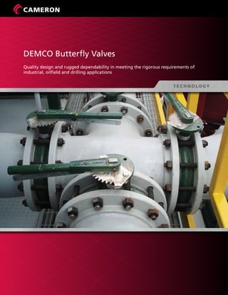
  • 1. DEMCO Butterfly Valves Quality design and rugged dependability in meeting the rigorous requirements of industrial, oilfield and drilling applications
  • 2.
  • 3. 1 DEMCO BUTTERFLY VALVES Introduction........................................................................................... 2 Features and Benefits ............................................................................ 3 Styles and Accessories............................................................................ 6 Series NE-C, NE-I, NE-D, NEI-T................................................................ 9 Series NF-C............................................................................................ 10 Base Part Numbers and Weights............................................................ 12 Marine Series......................................................................................... 13 Component Parts List............................................................................. 14 Dimensional Data (Valves)...................................................................... 16 Handles................................................................................................. 22 Worm Gear Operators........................................................................... 23 Stem Extensions..................................................................................... 25 General Technical Information................................................................ 26 Torque Data........................................................................................... 31 Standard Material Data.......................................................................... 32 Material Selection Guide........................................................................ 33 Services for Valves and Actuation........................................................... 39 Trademark Information.......................................................................... 40 Table of Contents
  • 4. 2 DEMCO Butterfly Valves Cameron is a leading provider of valves, valve automation, and measurement systems to the oil and gas industry. Our products are primarily used to control, direct and measure the flow of oil and gas as it is moved to refineries, petrochemical plants, and industrial centers for processing. We provide valve products that are sold through distributor networks worldwide for use in both oil and gas and industrial applications and include such widely recognized brands as DEMCO® , NAVCO® , NEWCO® , NUTRON® , THORNHILL CRAVER® , TECHNO™ , TOM WHEATLEY® , WHEATLEY® , and WKM® . Cameron’s DEMCO butterfly valves are the valves of choice, engineered and proven for drilling and production industries. Designed for dependable, heavy-duty performance in abrasive and corrosive service conditions, DEMCO butterfly valves are commonly selected for a number of oilfield applications. Oklahoma City, Okla., USA
  • 5. 3 FEATURES AND BENEFITS As one of the most durable resilient-seated butterfly valves in the industry, Cameron’s DEMCO butterfly valve excels in a variety of applications. Cast in both wafer and tapped lug patterns in a variety of material choices, DEMCO butterfly valves feature a one-piece body for reduced weight and increased strength. The unique stem hole design in the disc ensures the dry stem journal, and the hard-backed seat allows ease of installation, reliable operation and in-field repairability without special tools. DEMCO butterfly valves are available in sizes 2” to 36” (50 mm to 900 mm). Engineered for long-term, reduced-maintenance performance, DEMCO butterfly valves are commonly selected for a variety of applications in the following industries: • Chemical and petrochemical • Agriculture • Oil and gas drilling and production • Food and beverage • Water and waste water • Cooling towers (HVAC) • Power • Mining and materials • Dry bulk handling • Marine and government Bi-Directional Sealing Cameron’s DEMCO butterfly valve provides bi-directional sealing at full-rated pressure with identical flow from either direction. Integral Flange Seal An integral flange seal molded into the edge of the seat accommodates ASME weld neck, slip-on, threaded, socket and stub end type C flanges. ASME Class 150 Rating With a body rating of ASME Class 150 (285 psi non-shock), the wafer body diameters are designed to self-center in the ASME Class 150 flange pattern. Flatted Double D Upper Stem Large Flange Top for Ease of Power Automation Positive Stem Retention for Blowout-Proof Stems MSS-SP-25 Marking is Standard Triple Stem Seal High-Flow Disc Bronze Bearings Positively Oriented Disc Hard-Backed Cartridge Seat Wafer Style Shown One-Piece Body
  • 6. 4 Multiple Pressure Ratings Three drop-tight pressure ratings are offered for 2” to 12” (50 mm to 300 mm) sizes. The standard shut-off pressure rating is 200 psi, but 285 and 50 psi shut-off ratings are also available. A throttling 0 psi-rated valve is available where drop-tight closure is not required and minimal torque is desired. Both the 50 psi and throttling ratings allow for smaller actuators, which can significantly reduce overall installation cost in automated applications. The 14” to 36” (350 mm to 900 mm) size valves are available in 150 and 50 psi drop-tight shut-off ratings, as well as throttling. A. Dry Stem Journal Reduces Potential for Leakage The DEMCO valve’s disc is uniquely designed with a continuous annular-raised band around the stem hole and disc edge, which presses into the seat flat at every angular position. The resilient seat presses back with a higher force than the line pressure, preventing leakage to the stem. In addition, two O-ring ribs are provided in the seat stem bore, creating a triple stem seal. In competitive stem seal designs with boot seats, a seal is accomplished by an interference squeezing on the stem or an O-ring in the stem journal. The potential for leakage behind the seat is high for this competitive design. As the disc wipes the seat, elongation of the stem seal area allows leakage to collect behind the seat. This condition is reduced by the DEMCO valve’s dry stem journal and hard- backed seat. B. Hard-Backed Cartridge Seat The DEMCO valve’s cartridge seat is constructed by permanently bonding a resilient elastomer to a rigid backing ring. In addition to superior sealing integrity, this design: • Makes valve installation easier because no special precautions are required for disc position. This is especially advantageous when installing valves with fail-closed actuators. • Reduces high torque and premature failure caused by elastomer distortion, as found in other non-rigid seat designs. • Simplifies seat replacement because the seat is slip-fitted into the body with no need for special tools. Hard-Backed Seat BA FEATURES AND BENEFITS (CONT.)
  • 7. 5 C. Positively Oriented Disc The rectangular drive ensures the proper orientation of the stem disc connection. In 2” to 24” (50 mm to 600 mm) size valves, the disc is permitted to float on the stem to center in the valve seat. This design enhances drop-tight sealing and prolongs service life. Sizes 2” to 36” (50 mm to 900 mm) Body Type and Style Designations Long-Neck NE-C and NF-C: 2” to 36” (50 mm to 900 mm) wafer/lug, 36” (900 mm) Short-Neck NE-I and NE-I Sanitary: 2” to 12“ (50 mm to 300 mm) wafer/lug NE-IT Teflon: 2” to 10” (50 mm to 250 mm) wafer/lug NE-D: 2” to 12” (50 mm to 300 mm) wafer Marine: 2” to 24” (50 mm to 600 mm) wafer/lug Pressure Rating 2“ to 12” (50 mm to 300 mm): 0 (throttling); 50, 200 and 285 psi NEI-T: 2” to 10” (50 mm to 250 mm): 150 psi 14” to 36” (350 mm to 900 mm): 0, 50 and 150 psi Operating Temperatures -30º F to 300º F (-34º C to 204º C), depending on seat material selection and application (see page 32) Standard Material Options Bodies: Iron, steel, stainless steel and bronze Discs: Nickel-plated ductile iron, bronze and stainless steel Stems: 416 and 316 stainless steel Seats: Buna-N, EPDM, FKM and Neoprene *Many more options available (consult Cameron or see pages 9, 10 and 11 on how to order). D. End-of-Line Service Lug body valves may be used in end-of-line service with downstream piping removed. Only weld-neck or socket flanges can be used for this service. Since upstream pressure is excluded between the flange and the seat face by the DEMCO flange seal design, there is no effective force to slide the seat downstream. DEMCO 2” to 12” (50 mm to 300 mm) lug butterfly valves are suitable for liquid service up to 200 psi with downstream piping removed at 150 psi for 14” to 36” (350 mm to 900 mm) valves. Lug body valves are recommended for isolation of pumps, control devices or other system components, which may need to be removed for repair or replacement. Lug valves also are suitable for installation at points from which piping expansion may proceed. Such valves normally are blanked with blind flanges to protect the exposed seats until new piping is attached. Upstream Disc Disc Stem D C SPECIFICATIONS
  • 8. 6 STYLES AND ACCESSORIES The DEMCO butterfly valve comes in a variety of styles to suit a range of applications. In addition, a variety of quality accessories are available to further enhance its suitability to the application. Series NE-C Sizes 2” to 12” (50 mm to 300 mm) are available in both wafer and lug styles. This series is a general purpose valve with a neck length designed to provide full clearance for the valve top over 2” of insulation on ASME Class 150 pipe flanges. Series NE-I Sizes 2” to 12” (50 mm to 300 mm) are suited for a range of applications in many industries, including food and beverage utilities and process flowlines. This short neck design is offered in a variety of body materials. The valves are designed for installation between ASME Class 125 and 150 flanges. Series NE-D The valves in this series can be made in sizes 2” to 12” (50 mm to 300 mm). The Series NE-D valve is a short-neck valve with body notches to fit popular, lightweight flange patterns, making it ideal for both the bulk material handling and the transportation industries. Valves also will center in ASME Class 125 and 150 flanges. Series NF-C Sizes 14” to 36” (350 mm to 900 mm) are available in both wafer and lug styles. The wafer body has two drilled locator lugs at the top and bottom for ASME Class 150 flanges. Bronze bearings are installed on both stems for reduced operating torque.
  • 9. 7 Series NE-I Sanitary This series comes in sizes 2” to 12” (50 mm to 300 mm). It is similar to the Series NE-I valve, but is exclusively designed to meet the rigorous requirements of sanitary service in the food and beverage industry. The body is available in bronze, stainless steel, aluminum or electroless nickel-coated ductile iron. FDA-approved materials are used for all wetted parts. Handle parts are bronze and stainless steel, permitting caustic washdown. Other benefits: • The DEMCO dry journal stem seal system ensures sanitary butterfly valve construction. • Drilled passageways, a design originated by the DEMCO brand, vent the entire interior of the disc. No closed chamber is provided for the culture of undesirable organisms. • Discs are produced from smooth and non-porous investment castings. Stem bosses are reduced for increased flow. • The mating flange contacts and compresses the projecting inner surface of the resilient seat to form a smooth and uninterrupted flow way. This positive seal between the innermost contact of the seat and flange ensures aseptic conditions after a piping flush. Sanitary Features Series NEI-T Teflon Because of the inert, aseptic, non-stick character of Teflon® , the DEMCO NEI-T Teflon-lined butterfly valve is ideal for clean lines in food and beverage plants. The Teflon seat consists of a virgin Teflon liner overlaid and bonded to an elastomer EPDM cushion, which provides resilience for sealing. The Teflon liner extends over the seat faces, completely covering and sealing the resilient material from contact with line fluids. Marine DEMCO marine butterfly valves are available in the NE-C lug, NE-I lug and wafer, and NE-D wafer styles, and conform to: • Title 46 of the Code of Federal Regulations • Part 56 of the US Coast Guard’s Marine Engineering Regulations • The American Bureau of Shipping Standard, including tagging per MSS-SP-25 and testing per MSS-SP-67 Stem Seal Vented Design High-Flow Discs Trap-Free Flow Way
  • 10. 8 A. Actuators Consult Cameron or visit www.c-a-m.com/valveautomation for actuation options. B. Handles and Stem Extensions There are three basic handle designs that are compatible with any 2” to 12” (50 mm to 300 mm) valve: ten-position locking, two-position locking and memory stop. Memory- stop handles provide throttling, which is infinitely adjustable and can be set by a lock nut with a memory-stop setting (adjustable open stop). Handles are available in basic trim, corrosion-resistant trim and sanitary trim. Stem extensions are fabricated from carbon steel parts and contained in a tubular housing. Gaskets and O-rings seal the stem extension at the top and bottom. These extensions are fabricated to specified lengths. C. Gear Operators DEMCO weatherproof gear operators are offered with a choice of handwheel, chainwheel or square nuts. The worm gear has either self-locking set screws to control open and closed positioning or an optional adjustable memory-stop for balance return to a preset open position after closing. A. DEMCO NE-C Wafer B. Stem Extension with Handle on Series NE-I Butterfly Valve C. Gear-Operated STYLES AND ACCESSORIES (CONT.)
  • 11. 9 SERIES NE-C, NE-I, NE-D, NEI-T 2” to 12” (50 mm to 300 mm) Key No. Qty. Description Material 1 1 Body * 2 1 Seat * 3 1 Disc * 4 1 Upper Stem * 6 1 Lower Stem * 7 2 Spring Pin Stainless Steel 14 1 Retainer Stainless Steel 22 1 Top O-ring Buna-N 23 • Stem O-ring Buna-N 24 2 Bearing Bronze * See How to Order for material choices/styles. Complete material specs on page 32. • Four required for throttling valves only. HOW TO ORDER (Example: 6” (150 mm) NE-C, 200 psi, Wafer, Standard Trim with Handle – 22124-1215311) * Standard coating is green enamel; other coatings are available on request. ** 17-4 PH SS for 8” to 12” (200 mm to 300 mm) upper stem only. *** Except 17-4 PH upper 8” and 10” (200 mm and 250 mm). 1 200 psi only. 2 Except 285 psi. 3 Polished – ground to #4 dairy finish; tumbled – vibratory finish to remove as cast surface; unpolished – as cast surface. 4 When these options are used with NE-I sanitary butterfly valves, handles will be bronze with stainless steel (SS) parts and fasteners. 5 Gear operator recommended for 8” to 12” (200 mm to 300 mm) sizes in all series. 6 See material trademark note on page 40. 7 Other seat options available (consult Cameron). Handle 10 Position Lkg. 14 Throttling Mem./ Stop 24 Square Nut 5 2-Position Lkg. 64 10-Position Sanitary (NEI-T Only) 8 None 9 10-Position Lkg. Corrosion-Resistant K 2-Position Lkg. Corrosion-Resistant L Throttling Mem./ Stop Corrosion- Resistant M Gear Operators5 Handwheel A Crank 2” to 12” (50 mm to 300 mm) B Chainwheel C Square Nut D Bare Shaft E NE-C, NE-I and NE-D7 Buna-N 31 Black Neoprene 32 Hypalon6 33 FKM 34 Peroxide-Cured, EPDM 35 Natural Rubber 36 White Neoprene 37 ETM-30230 01 Fluorosteam 02 Peroxide-Cured Food Grade, EPDM 03 Peroxide-Cured, Buna-N 04 Sulfur-Cured Food Grade, EPDM 05 NEI-T Peroxide-Cured,EPDM/Teflon6 35 Sulfur-Cured, EPDM/Teflon6 05 NE-I Sanitary All Seats Food Grade Black Neoprene 32 FKM 34 EPDM 35 White Neoprene 37 Sulfur-Cured, EPDM 05 NE-C, NE-I and NE-D 316 SS 2 Monel6 3 Aluminum Bronze 4 Ductile Iron, Nickel-Plated 5 PVF-Coated Ductile Iron1 6 Alloy 202 7 Hastelloy “C”6 8 NEI-T and NE-I Sanitary 316 SS Polished3 2 316 SS Tumbled3 5 Alloy 20 (NEI-T Only) 7 Hastelloy “C”6 (NEI-T Only) 8 316 SS Unpolished3 9 NE-C, NE-I and NE-D 416 SS 1 316 SS** 2 Monel6 3 NEI-T 316 SS Vented*** 2 316 SS Solid*** 9 NEI-Sanitary 316 SS*** 2 NE-C (Long-Neck) Ductile Iron (Lug) 1 Cast Iron (Wafer) 2 NE-I and NE-I Sanitary Ductile Iron (NE-I,Wafer Only) 1 Aluminum Bronze 3 Carbon Steel (NE-I Only) 4 Aluminum (NE-I,Wafer Only) 5 ENC-Coated Ductile Iron 6 Stainless Steel 8 NE-D Ductile Iron 1 NEI-T Ductile Iron Wafer – Short-Neck Lug – Long-Neck 1 Gray Iron (Long-Neck Wafer) 2 Aluminum Bronze 3 Carbon Steel 4 Aluminum (Wafer Only) 5 Stainless Steel 8 NE-C/NE-I/NEI-T Wafer 1 Lug 5 NE-D Wafer 1 Based on valve series and shut-off pressure. See page 12. X X X X X Base Part Number - X X X X XX X Body Configuration Body Material* Stem Material Disc Material Seat Elastomer Actuation 22 24 4 14 24 1 7 23 2 3 1 1 1 1 6 723 Series NE-C Wafer Series NE-I Wafer Series NE-I Lug Series NE-D Wafer Series NE-C Lug
  • 12. 10 SERIES NF-C 14” to 24” (350 mm to 600 mm) Key No. Qty. Description Material 1 1 Body * 2 1 Seat * 3 1 Disc * 4 1 Upper Stem * 6 1 Lower Stem * 7 2 Spring Pin Stainless Steel 14 1 Retainer (Spacer) + Stainless Steel 22 1 Top O-ring Buna-N 23 • Stem O-ring Buna-N 24 2 Bearing Bronze HOW TO ORDER (Example: 18” (450 mm) NF-C, 150 psi Lug, SS Trim, Buna-N Seat, WGO – 23822-512231A) None 9 Gear Operators Handwheel A Chainwheel C Square Nut D Bare Shaft E Buna-N 31 Black Neoprene 32 Hypalon6 33 FKM 34 EPDM 35 316 SS 2 Monel2 3 Aluminum Bronze 4 Nickel-Plated Iron 5 PVF-Coated Ductile Iron1 6 416 SS 1 316 SS 2 Monel2 3 Ductile Iron (Lug) 1 Cast Iron (Wafer) 2 Aluminum Bronze (Lug) 3 Steel (Lug) 4 Stainless Steel (Lug) 8 Wafer 1 Lug 5 X X X X X Base Part Number - X X X X XX X Body Configuration Body Material* Stem Material Disc Material Seat Elastomer Actuation Based on valve series and shut-off pressure. See page 12. * See How to Order for material choices/styles. Complete material specs are on page 32. • Four required for throttling valves only. + 14” to 20” (350 mm to 500 mm) spacer. * Standard coating is green enamel; other coatings are available on request. 1 150 psi only. 2 See material trademark note on page 40. 1 1 6 7 2 23 3 25 23 23 23 24 4 7 14 24
  • 13. 11 SERIES NF-C 30“ and 36” (750 mm and 900 mm) Key No. Qty. Description Material 1 1 Body * 2 1 Seat – Hard-Backed * 3 1 Disc * 4 1 Upper Stem * 6 1 Lower Stem * 7 2 Disc Screw 18-8 SS 8 1 Key Stainless Steel 9 2 O-ring Buna-N 14 1 Spacer Steel 24 2 Upper Bearing Bronze 25 1 Lower Bearing Bronze 26 1 Thrust Collar Bronze 27 1 Set Screw 18-8 SS 28 1 Cap Ductile Iron 29 4 Screw Carbon Steel 30 4 Lockwasher Carbon Steel * See How to Order for material choices/styles. Complete material specs on page 32. HOW TO ORDER (Example: 36 “ (900 mm), 150 psi, Bronze Disc, EPDM Seat with Gear Op. – 24357-111435A) * Standard coating is green enamel; other coatings are available on request. 1 See material trademark note on page 40. Handwheel A Chainwheel C Square Nut D Bare Shaft E Buna-N 31 FKM 34 EPDM 35 316 SS 2 Monel1 3 Aluminum Bronze 4 Ductile Iron, Nickel- Plated 5 416 SS 1 316 SS 2 Monel1 3 Ductile Iron (Wafer or Lug) 1Wafer 1 Lug 5 See page 12. X X X X X Base Part Number - X X X X XX X Body Configuration Body Material* Stem Material Disc Material Seat Elastomer Actuation 4 1 2 3 8 24 14 24 9 27 7 6 25 26 28 29 30
  • 14. 12 BASE PART NUMBERS AND WEIGHTS Description in. 2 2-1/2 3 4 5 6 8 10 12 (mm) (50) (65) (80) (100) (125) (150) (200) (250) (300) 200 psi 22119 22120 22121 22122 22123 22124 22125 22126 22127 285 psi 22225 22226 22227 22228 22229 22230 22231 22232 22233 50 psi 22234 22235 22236 22237 22238 22239 22240 22241 22242 Throttling 22243 22244 22245 22246 22247 22248 22249 22250 22251 Weight (lb – bare stem) Wafer 5.8 7.0 7.7 11.4 14.7 17.6 28.5 47.9 71.0 Lug 8.0 9.9 10.7 17.0 24.5 28.5 43.5 65.9 98.5 Description in. 2 2-1/2 3 4 5 6 8 10 12 (mm) (50) (65) (80) (100) (125) (150) (200) (250) (300) 200 psi 22128 22129 22130 22131 22132 22133 22134 22135 22136 285 psi 22252 22253 22254 22255 22256 22257 22258 22259 22260 50 psi 22261 22262 22263 22264 22265 22266 22267 22268 22269 Throttling 22270 22271 22272 22273 22274 22275 22276 22277 22278 Weight (lb – bare stem) Wafer Iron, Steel, SS 4.9 6.4 6.9 10.2 13.7 16.4 28.4 44.8 66.8 Bronze 4.7 6.2 6.7 9.9 13.4 16.0 28.0 44.3 66.3 Aluminum 2.8 3.4 4.1 5.9 8.7 10.8 18.2 30.4 47.2 (lb – bare stem) Lug Bronze 6.8 8.7 9.5 15.7 23.1 27.0 42.0 64.4 96.8 Steel, SS 7.0 8.9 9.7 16.0 23.5 27.5 42.5 64.9 97.5 Description in. 2 2-1/2 3 4 6 8 10 12 (mm) (50) (65) (80) (100) (150) (200) (250) (300) 200 psi 23150 23151 23152 23153 23154 23155 23156 23157 Weight See chart above: NE-I, 2” to 12” (50 mm to 300 mm) Description in. 2 2-1/2 3 4 5 6 8 10 12 (mm) (50) (65) (80) (100) (125) (150) (200) (250) (300) 200 psi 22181 22129 25093 22183 22184 22185 22134 22186 22136 285 psi 22279 22253 25135 22281 22282 22283 22258 22284 22260 50 psi 22285 22262 25132 22287 22288 22289 22267 22290 22269 Throttling 22291 22271 25136 22293 22294 22295 22276 22296 22278 Weight (lb – bare stem) Wafer 4.9 6.4 6.9 10.2 13.7 16.4 28.4 44.8 66.8 Description in. 2 2-1/2 3 4 6 8 10 (mm) (50) (65) (80) (100) (150) (200) (250) 150 psi 24680 24681 24682 24683 24684 24685 24686 Weight (lb – bare stem) Wafer** Iron, Steel, SS 4.9 6.4 6.9 10.2 16.4 28.4 44.8 Bronze 4.7 6.2 6.7 9.9 16.0 28.0 44.3 Aluminum 2.8 3.4 4.1 5.9 10.8 18.2 30.4 (lb – bare stem) Lug** Bronze 6.8 8.7 9.5 15.7 27.0 42.0 64.4 Steel, SS 7.0 8.9 9.7 16.0 27.5 42.5 64.9 Description in. 14 16 18 20 24 (mm) (350) (400) (450) (500) (600) 150 psi 23820 23821 23822 23823 23824 50 psi 24440 24441 24442 24443 24444 Throttling 24445 24446 24447 24448 24449 Weight (lb – bare stem) Wafer 102 166 214 257 401 Lug 116 203 239 332 535 * Gear operator recommended for 8” to 12” (200 mm to 300 mm) sizes. ** See NE-C chart above for weights of long-neck wafer and lug valves. Marine valves: consult Cameron for data sheets B-255, B-256 and B-258. Description in. 30 36 (mm) (750) (900) 150 psi 24141 24357 50 psi 24924 25061 Weight Wafer 935 1500 Lug 1050 2020 Series NE-C, 2” to 12“ (50 mm to 300 mm)* Series NE-I, 2” to 12“ (50 mm to 300 mm)* Series NE-I, Sanitary 2” to 12“ (50 mm to 300 mm)* Series NE-D, 2” to 12“ (50 mm to 300 mm)* Series NEI-T, 2” to 10“ (50 mm to 250 mm)* Series NF-C, 14” to 24“ (350 mm to 600 mm) Series NF-C, 30” to 36“ (750 mm to 900 mm)
  • 15. 13 DEMCO marine butterfly valves meet all the requirements of US Coast Guard’s Marine Engineering Regulations as outlined in Title 46 of the Code of Federal Regulations, Part 56 and The American Bureau of Shipping Standard, including tagging per MSS-SP-25 and testing per MSS-SP-67. All valves are shell tested at 1-1/2 times rated working pressure and seat tested at rated working pressure. Description in. 2 2-1/2 3 4 5 6 8 10 12 (mm) (50) (65) (80) (100) (125) (150) (200) (250) (300) 200 psi 22923 22924 22925 22926 22927 22928 22929 22930 22931 50 psi 22932 22933 22934 22935 22936 22937 22938 22939 22940 285 psi 22914 22915 22916 22917 22918 22919 22920 22921 22922 Weight (lb – bare stem) NE-C Long-Neck Body Wafer Gray Iron 5.8 7.0 7.7 11.4 14.7 17.6 28.5 47.9 71.0 Lug Ductile Iron 8.0 9.9 10.7 17.0 24.5 28.5 43.5 65.9 98.5 NE-I Short-Neck Body Wafer Iron, Steel, SS 4.9 6.4 6.9 10.2 13.7 16.4 28.4 44.8 66.8 Bronze 4.7 6.2 6.7 9.9 13.4 16.0 28.0 44.3 66.3 Lug Bronze 6.8 8.7 9.5 15.7 23.1 27.0 42.0 64.4 96.8 SS, Steel 7.0 8.9 9.7 16.0 23.5 27.5 42.5 64.9 97.5 Description in. 14 16 18 20 24 30 36 (mm) (350) (400) (450) (500) (600) (750) (900) 150 psi 24611 24612 24613 24614 24615 2227182 2227183 50 psi 24653 24654 24655 24656 24657 2227184 2227185 Weight (lb – bare stem) NF-C Long-Neck Body Lug Ductile Iron 116 203 239 332 535 1050 2020 Bronze 113 199 235 325 525 N/A N/A HOW TO ORDER (Example: 6” (150 mm) 200 psi Wafer, Standard Trim with 10-Position Handle – 22928-1114311) 10-Position Handle 1 Throttling Memory Stop 2 2-Position Locking 6 Worm Gear Handwheel A Buna-N* 31 Black Neoprene 32 Hypalon1 33 FKM 34 EPDM* 35 Natural Rubber 36 White Neoprene 37 Stainless Steel 2 Monel1 3 Aluminum Bronze* 4 416 SS* 1 316 SS 2 Monel1 3 Ductile Iron 1 Aluminum Bronze 3 Carbon Steel 4 Stainless Steel 8 Wafer 1 Lug 5 X X X X X Base Part Number - X X X X XX X Body Configuration Body Material* Stem Material Disc Material Seat Material Actuation Base part no. of valve shown above. * Standard base trim options. ** Wafer 2” to 12” (50 mm to 300 mm) only. Lug 2” to 36” (50 mm to 900 mm). Note: 30” and 36” (750 mm to 900 mm) available with ductile iron lug body only. 1 See material trademark note on page 40. MARINE SERIES Marine Series, 2” to 36“ (50 mm to 900 mm)
  • 16. 14 COMPONENT PARTS LIST: SERIES NE-C, NE-I, NE-D Key Description 2” 2-1/2” 3” 4” 5” 6” 8” 10” 12” No. (50 mm) (65 mm) (80 mm) (100 mm) (125 mm) (150 mm) (200 mm) (250 mm) (300 mm) 1 Body NE-C Wafer Options 22137-012 22138-012 22139-012 22140-012 22141-012 22142-012 22143-012 22144-012 22145-012 ASTM A48 Gray Iron -012 NE-C Lug 21986-051 21987-051 21988-051 21989-051 21990-051 21991-051 21992-051 21993-051 21994-051 Options ASTM A395 Ductile Iron -051 NE-I Wafer 22681-01x 22682-01x 22683-01x 22684-01x 22685-01x 22686-01x 22687-01x 22688-01x 22689-01x Options ASTM A395 Ductile Iron -011, ASTM B148 Aluminum Bronze -013, ASTM A216 WCB Steel -014, ASTM B179 Aluminum -015, DI/ENC -016, ASTM A351 SS -018 NE-I Lug 22695-05x 22696-05x 22697-05x 22698-05x 22699-05x 22700-05x 22701-05x 22702-05x 22703-05x Options ASTM B148 Aluminum Bronze -053, ASTM A216 WCB Steel -054, ASTM A351 SS -058 NE-D Wafer 22187-021 22682-011 20594-021 22189-021 22190-021 22191-021 22687-011 22192-021 22689-011 Options ASTM A395 Ductile Iron -0x1 2 Seat 1786-xxx 1788-xxx 1790-xxx6 1792-xxx 1794-xxx 1002-xxx 1798-xxx 1815-xxx 1817-xxx Options Buna-N -031, Black Neoprene -032, Hypalon7 -033, FKM -034, EPDM1 -135, Natural Rubber -036 White Neoprene -037, Peroxide-Cured Buna-N -231, Fluorosteam -244, ETM-30230 -3313” NE-D Seat (See Below6 ) 3 Disc 200 psi 22045-0xx 22046-0xx 22047-0xx 22048-0xx 22049-0xx 22050-0xx 22051-0xx 22052-0xx 22053-0xx 285 psi 22196-0xx 22197-0xx 22198-0xx 22199-0xx 22200-0xx 22201-0xx 22202-0xx 22203-0xx 22204-0xx 50 psi 22205-0xx 22206-0xx 22207-0xx 22208-0xx 22209-0xx 22210-0xx 22211-0xx 22212-0xx 22213-0xx Throttling 22214-0xx 22215-0xx 22216-0xx 22217-0xx 22218-0xx 22219-0xx 22220-0xx 22221-0xx 22222-0xx Options 316 SS -002, Monel -003, Nickel-Plated Ductile Iron -005, Alloy 202 -007, Hastelloy C7 -008, Aluminum Bronze3 -014 PVF-Coated, 200 psi 22714-001 22715-001 22716-001 22717-001 22718-001 22719-001 22720-001 22721-001 22722-001 4 Upper Stem NE-C 22066-00x 22067-00x 22068-00x 22069-00x 22070-00x 22071-00x 22072-00x NE-I 22073-00x 22074-00x 22075-00x 22076-00x 22077-00x 22078-00x 22079-00x NE-D 22073-00x 22074-00x 22193-00x 22194-00x 22195-00x 22077-00x 22078-00x 22079-00x Upper Stem NE-C 22334-00x 22335-00x 22336-00x 22337-00x 22338-00x 22339-00x 22340-00x -Utility Top NE-I 22341-00x 22342-00x 22343-00x 22344-00x 22345-00x 22346-00x 22347-00x 6 Lower Stem 22080-00x 22081-00x 22082-00x 22083-00x 22084-00x 22085-00x 22086-00x Stem Material Options 416 SS -001, 316 SS4 -002, Monel7 -003 7 Spring Pin (2) 302 SS 5448-18720 5448-18724 5448-25028 14 Retainer Stainless Steel 22117 13704 13705 13706 13707 22 Top O-ring Buna-N 5526-114 5526-115 5526-117 5526-119 5526-125 23 Stem O-ring5 Buna-N 5526-113 5526-115 5526-116 5526-212 5526-214 5526-220 24 Bearing (2) Bronze 22526-001 22118-001 13112-001 13115-001 13116-001 13117-001 1 EPDM seat options: Standard – Peroxide-Cured -135, Food Grade -035 Peroxide-Cured, Sulfur-Cured -235. 2 Alloy 20 not available for 285 psi. 3 8” to 12” (200 mm to 300 mm), 285 psi Aluminum Bronze, use -024. 4 8” to 12” (200 mm to 300 mm), Upper Stem 17-4 PH SS (part number suffix -012), Lower Stem 316 SS. 5 Four required for throttling (0 psi) valves only. 6 3” (80 mm) NE-D seat part number 25095-xxx. 7 See material trademark note on page 40 1 1 1 7 6 23 22 24 7 14 24 4 1 1 2 3 23 Parts List for Series NE-C, NE-I and NE-D (Consult a Cameron representative for replacement parts for Series NE, NE-S and NE-N.)
  • 17. 15 COMPONENT PARTS LIST: SERIES NF-C 1 Four required for throttling valves only. 2 14” to 20” (350 mm to 500 mm) retainer, 24” (600 mm) spacer. 3 EPDM seat options: Standard – Peroxide-Cured -135, Food Grade -035 Peroxide-Cured, Sulfur-Cured -235. 4 See material trademark note on page 40. Key Qty. Description 14” 16” 18” 20” 24” Material No. (350 mm) (400 mm) (450 mm) (500 mm) (600 mm) 1 1 Body Lug 23827-051 23911-051 23901-051 23891-051 23875-051 Ductile Iron (Lug) -051 Wafer 23825-012 23907-012 23899-012 23881-012 23873-012 Cast Iron (Wafer) -012 Buna-N -031 Blk. Neoprene -032 2 1 Seat 23829-03x 23913-03x 23903-03x 23893-03x 7103-03x Hypalon4 -033, FKM -034 EPDM3 -X35 Disc 150 psi 23830-0xx 23915-0xx 23905-0xx 23895-0xx 23877-0xx 316 SS -002 Monel4 -003 3 1 50 psi 24450-0xx 24451-0xx 24452-0xx 24453-0xx 24454-0xx Aluminum Bronze -014 Throttling 24455-0xx 24456-0xx 24457-0xx 24458-0xx 24459-0xx Nickel-Plated Iron -005 PVF-Coated 24460-001 24461-001 24462-001 24463-001 24464-001 PVF-Coated Iron -001 4 1 Upper Stem 23833-00x 23917-00x 23897-00x 23897-00x 23879-00x 416 SS -001, 316 SS -002 6 1 Lower Stem 23834-00x 23918-00x 23898-00x 23898-00x 23880-00x Monel4 -003 7 2 Spring Pin 5446-25040 5446-25040 5446-25048 5446-25048 5446-25064 Stainless Steel 14 1 Retainer (Spacer)2 5502-137 5502-150 5502-175 5502-175 24470 Steel 23 Note 1 Disc O-ring 5526-220 5526-223 5526-328 5526-328 5526-331 Buna-N 24 2 Upper Bearing 5086-044 5086-050 5086-048 5086-048 5086-046 Bronze 25 1 Lower Bearing 5086-045 5086-051 5086-049 5086-049 5086-047 Bronze 1 1 23 25 23 24 4 14 24 7 2 23 3 6 7 23 Part List for Series NF-C, (Consult a Cameron representative for replacement parts for Series NF.)
  • 18. 16 SERIES NE-C DIMENSIONAL DATA 2” to 12” (50 mm to 300 mm) Note: For general dimensions, see page 28. P N AE D F S G R H P C C R N Size in. A C D E F G H J K L N P R S 2 1.74 5.62 8.44 4.12 4.00 3.25 0.408 4.75 5/8 - 11 4 1.00 0.44 0.625 0.375 2-1/2 1.86 6.12 9.19 4.88 4.00 3.25 0.408 5.50 5/8 - 11 4 1.00 0.44 0.625 0.375 3 1.86 6.38 9.69 5.38 4.00 3.25 0.408 6.00 5/8 - 11 4 1.00 0.44 0.625 0.375 4 2.11 7.12 11.00 6.88 4.00 3.25 0.408 7.50 5/8 - 11 8 1.00 0.44 0.625 0.375 5 2.24 7.75 12.12 7.75 4.00 3.25 0.408 8.50 3/4 - 10 8 1.25 0.44 0.838 0.500 6 2.24 8.25 13.25 8.75 4.00 3.25 0.408 9.50 3/4 - 10 8 1.25 0.44 0.838 0.500 8 2.54 9.44 15.56 11.00 6.00 5.00 0.533 11.75 3/4 - 10 8 1.38 0.56 0.838 0.500 10 2.74 11.25 18.69 13.38 6.00 5.00 0.533 14.25 7/8 - 9 12 1.38 0.56 0.963 0.625 12 3.24 12.19 21.69 16.12 6.00 5.00 0.533 17.00 7/8 - 9 12 1.38 0.56 1.338 0.750 Size mm 50 44 143 214 105 102 83 10.36 121 5/8 - 11 4 25 11.2 15.88 9.53 65 47 155 233 124 102 83 10.36 140 5/8 - 11 4 25 11.2 15.88 9.53 80 47 162 246 137 102 83 10.36 152 5/8 - 11 4 25 11.2 15.88 9.53 100 54 181 279 175 102 83 10.36 191 5/8 - 11 8 25 11.2 15.88 9.53 125 57 197 308 197 102 83 10.36 216 3/4 - 10 8 32 11.2 21.29 12.70 150 57 210 337 222 102 83 10.36 241 3/4 - 10 8 32 11.2 21.29 12.70 200 65 240 395 279 152 127 13.54 298 3/4 - 10 8 35 14.2 21.29 12.70 250 70 286 475 340 152 127 13.54 362 7/8 - 9 12 35 14.2 24.46 15.88 300 82 310 551 409 152 127 13.54 432 7/8 - 9 12 35 14.2 33.99 19.05 Dimensional Data
  • 19. 17 SERIES NF-C DIMENSIONAL DATA 14” to 24” (350 mm to 600 mm) Size in. A B C D E G H J K L M N P R S T U 14 3.00 10.63 12.75 23.4 16.20 5.00 0.56 18.75 1 - 8 12 2.00 2.25 0.88 1.375 5/16 x 5/32 5.12 12.89 17.3* 1* 16 4.00 11.66 13.75 25.4 18.16 5.00 0.56 21.25 1 - 8 16 2.00 2.25 0.88 1.625 3/8 x 3/16 5.65 14.76 19.2* 1* 18 4.50 12.96 14.75 27.7 20.35 6.50 0.81 22.75 1-1/8 - 7 16 2.50 2.75 1.00 1.875 1/2 x 3/16 6.37 16.63 21.4* 1-1/8* 20 5.00 13.97 15.75 29.7 22.63 6.50 0.81 25.00 1-1/8 - 7 20 2.50 2.75 1.00 1.875 1/2 x 3/16 7.12 18.58 23.6* 1-1/8* 24 6.00 16.19 19.00 35.2 27.31 6.50 0.81 29.50 1-1/4 - 7 20 2.50 3.00 1.00 1.875 1/2 x 3/16 8.67 22.56 28.3* 1-1/4* Size mm 350 76 270 324 594 411 127 14.2 476 1 - 8 12 51 57 22.4 34.93 7.94 x 3.97 130 327 439* 1* 400 102 296 349 645 461 127 14.2 540 1 - 8 16 51 57 22.4 41.28 9.53 x 4.76 144 375 488* 1* 450 114 329 375 704 517 165 20.6 578 1-1/8 - 7 16 64 57 25.4 47.63 12.70 x 4.76 162 422 544* 1-1/8* 500 127 355 400 754 575 165 20.6 635 1-1/8 - 7 20 64 57 25.4 47.63 12.70 x 4.76 181 472 599* 1-1/8* 600 152 411 483 894 694 165 20.6 749 1-1/4 - 7 20 64 76 25.4 47.63 12.70 x 4.76 220 573 719* 1-1/4* * Wafer valve dimension is the bottom figure. Lug valve dimension is the top figure. Note: For general dimensions, see page 28. T U AE D G R H P C M S N B Dimensional Data
  • 20. 18 SERIES NF-C DIMENSIONAL DATA 30” to 36” (750 mm to 900 mm) Note: For general dimensions, see page 28. Size in. A B C D E G H J K L M N P R S T U V 30 6.50 21.2 23.0 44.2 34.1 8.00 0.69 36.00 1-1/4 - 7UNC 28 3.4 3.7 1.2 3.000 3/4 x 3/8 11.45 28.55 1.750 36 7.88 25.0 27.8 52.8 40.5 10.25 0.81 42.75 1-1/2 - 6UNC 32 4.0 4.4 1.5 3.625 7/8 x 7/16 13.86 34.71 1.750 Size mm 750 165 538 584 1123 866 203 17.53 914 1-1/4 - 7UNC 28 86 94 30.5 76.2 19.05 x 9.53 291 725 44.45 900 200 635 706 1342 1029 260 20.57 1086 1-1/2 - 6UNC 32 102 112 38.1 92.1 22.23 x 11.11 352 882 44.45 For ASME Class 150 Series A and MSS-SP-44 Flanged Pattern 4 Locating lugs for ASME Class 150 Series A and MSS SP-44 Flanged Pattern J–Bolt Circle K–Bolt Size L–No. of Bolts Total V–Depth of Thread J–Bolt Circle K–Bolt Size L–No. of Bolts Total V–Depth of Thread T U AE D G R H P C M S N B R N Dimensional Data
  • 21. 19 SERIES NE-D DIMENSIONAL DATA 2” to 12” (50 mm to 300 mm) Size in. A C D E F G H J K L N P R S 2 1.74 3.94 6.75 4.12 4.00 3.25 0.408 4.27 3/8 4 1.00 0.44 0.625 0.375 2-1/2 1.86 4.44 7.50 4.88 4.00 3.25 0.408 5.31 3/8 4 1.00 0.44 0.625 0.375 3 1.86 4.88 8.19 5.38 4.00 3.25 0.408 4.91 3/8 6 1.00 0.44 0.625 0.375 4 2.11 6.00 9.88 6.88 4.00 3.25 0.408 7.03 1/2 6 1.00 0.44 0.625 0.375 5 2.24 6.00 10.38 7.75 4.00 3.25 0.408 7.56 1/2 6 1.25 0.44 0.838 0.500 6 2.24 6.50 11.50 8.75 4.00 3.25 0.408 9.16 1/2 8 1.25 0.44 0.838 0.500 8 2.54 8.06 14.19 11.00 6.00 5.00 0.533 11.72 5/8 8 1.38 0.56 0.838 0.500 10 2.74 9.97 17.41 13.38 6.00 5.00 0.533 13.72 5/8 8 1.38 0.56 0.963 0.625 12 3.24 10.91 20.41 16.12 6.00 5.00 0.533 16.62 1/2 12 1.38 0.56 1.338 0.750 Size mm 50 44 100 171 105 102 83 10.36 108 10 4 25 11.2 15.88 9.53 65 47 113 191 124 102 83 10.36 135 10 4 25 11.2 15.88 9.53 80 47 124 208 137 102 83 10.36 125 10 6 25 11.2 15.88 9.53 100 54 152 251 175 102 83 10.36 179 15 6 25 11.2 15.88 9.53 125 57 152 264 197 102 83 10.36 192 15 6 32 11.2 21.29 12.70 150 57 165 292 222 102 83 10.36 233 15 8 32 11.2 21.29 12.70 200 65 205 360 279 152 127 13.54 298 16 8 35 14.2 21.29 12.70 250 70 253 442 340 152 127 13.54 348 16 8 35 14.2 24.46 15.88 300 82 277 518 409 152 127 13.54 422 15 12 35 14.2 33.99 19.05 Note: For general dimensions, see page 28. J–Bolt Circle K–Stud Size L–No. of Studs E D P C A R N H G F S Dimensional Data
  • 22. 20 SERIES NE-I, NE-I SANITARY 2” to 12” (50 mm to 300 mm) Size in. A C D E F G H J K L N P R S 2 1.74 3.94 6.75 4.12 4.00 3.25 0.408 4.75 5/8 - 11 4 1.00 0.44 0.625 0.375 2-1/2 1.86 4.44 7.50 4.88 4.00 3.25 0.408 5.50 5/8 - 11 4 1.00 0.44 0.625 0.375 3 1.86 4.69 8.00 5.38 4.00 3.25 0.408 6.00 5/8 - 11 4 1.00 0.44 0.625 0.375 4 2.11 5.44 9.31 6.88 4.00 3.25 0.408 7.50 5/8 - 11 8 1.00 0.44 0.625 0.375 5* 2.24 6.38 10.75 7.75 4.00 3.25 0.408 8.50 3/4 - 10 8 1.25 0.44 0.838 0.500 6 2.24 6.88 11.88 8.75 4.00 3.25 0.408 9.50 3/4 - 10 8 1.25 0.44 0.838 0.500 8 2.54 8.06 14.19 11.00 6.00 5.00 0.533 11.75 3/4 - 10 8 1.38 0.56 0.838 0.500 10 2.74 9.97 17.41 13.38 6.00 5.00 0.533 14.25 7/8 - 9 12 1.38 0.56 0.963 0.625 12 3.24 10.91 20.41 16.12 6.00 5.00 0.533 17.00 7/8 - 9 12 1.38 0.56 1.338 0.750 Size mm 50 44 100 171 105 102 83 10.36 121 5/8 - 11 4 25 11.2 15.88 9.53 65 47 113 191 124 102 83 10.36 140 5/8 - 11 4 25 11.2 15.88 9.53 80 47 119 203 137 102 83 10.36 152 5/8 - 11 4 25 11.2 15.88 9.53 100 54 138 236 175 102 83 10.36 191 5/8 - 11 8 25 11.2 15.88 9.53 125* 57 162 273 197 102 83 10.36 216 3/4 - 10 8 32 11.2 21.29 12.70 150 57 175 302 222 102 83 10.36 241 3/4 - 10 8 32 11.2 21.29 12.70 200 65 205 360 279 152 127 13.54 298 3/4 - 10 8 35 14.2 21.29 12.70 250 70 253 442 340 152 127 13.54 362 7/8 - 9 12 35 14.2 24.46 15.88 300 82 277 518 409 152 127 13.54 432 7/8 - 9 12 35 14.2 33.99 19.05 * NE-I sanitary 5” (125 mm) not available. Note: For general dimensions, see page 28. J–Bolt Circle K–Stud Size L–No. of Studs H G F S E D P C A R N P C R N Dimensional Data
  • 23. 21 SERIES NEI-T 2” to 10” (50 mm to 250 mm) Size in. A C D E F G H J K L N P R S 2 1.74 3.94 6.75 4.12 4.00 3.25 0.408 4.75 5/8 - 11 4 1.00 0.44 0.625 0.375 2-1/2 1.86 4.44 7.50 4.88 4.00 3.25 0.408 5.50 5/8 - 11 4 1.00 0.44 0.625 0.375 3 1.86 4.69 8.00 5.38 4.00 3.25 0.408 6.00 5/8 - 11 4 1.00 0.44 0.625 0.375 4 2.11 5.44 9.31 6.88 4.00 3.25 0.408 7.50 5/8 - 11 8 1.00 0.44 0.625 0.375 6 2.24 6.88 11.88 8.75 4.00 3.25 0.408 9.50 3/4 - 10 8 1.25 0.44 0.838 0.500 8 2.54 8.06 14.19 11.00 6.00 5.00 0.533 11.75 3/4 - 10 8 1.38 0.56 0.838 0.500 10 2.74 9.97 17.41 13.38 6.00 5.00 0.533 14.25 7/8 - 9 12 1.38 0.56 0.963 0.625 Size mm 50 44 100 171 105 102 83 10.36 121 5/8 - 11 4 25 11.2 15.88 9.53 65 47 113 191 124 102 83 10.36 140 5/8 - 11 4 25 11.2 15.88 9.53 80 47 119 203 137 102 83 10.36 152 5/8 - 11 4 25 11.2 15.88 9.53 100 54 138 236 175 102 83 10.36 191 5/8 - 11 8 25 11.2 15.88 9.53 150 57 175 302 222 102 83 10.36 241 3/4 - 10 8 32 11.2 21.29 12.70 200 65 205 360 279 152 127 13.54 298 3/4 - 10 8 35 14.2 21.29 12.70 250 70 253 442 340 152 127 13.54 362 7/8 - 10 12 35 14.2 24.46 15.88 Note: For general dimensions, see page 28. J–Bolt Circle K–Stud Size L–No. of Lugs H G F S P C R N E D P C A R N Dimensional Data
  • 24. 22 HOW TO ORDER (X X X X X - 0 0 X) Standard 1 Corrosion-Resistant 2 Sanitary 3 Description in. 2 to 4 5 to 6 8 10 12 (mm) (50 to 100) (125 to 150) (200) (250) (300) 10-Position, Standard, CR 24227 24228 24229 24230 24231 2-Position, Standard, CR 24232 24233 24234 24235 24236 10-Position, Sanitary 22319 22320 22321 22322 22323 2-Position, Sanitary 22324 22325 22326 22327 22328 Throttling, Standard, CR 24252 24253 24254 24255 24256 Throttling, Sanitary 22329 22330 22331 22332 22333 Square Nut, Standard 23356 23357 23358 23359 22360 Weight (lb) 2.3 2.9 6.5 6.5 6.5 X X X X X - 00X Base Part Number Trim sq Key No. Description Material Standard Corrosion-Resistant Sanitary 5 Screw Steel Stainless Steel Stainless Steel 8 Handle Ductile Iron Ductile Iron Bronze 10 Latch Zinc-Plated Steel Stainless Steel Stainless Steel 11 Spring Spring Steel Stainless Steel Stainless Steel 12 Spring Pin Spring Steel Stainless Steel Stainless Steel 15 Throttle Plate Zinc-Plated Steel Stainless Steel Stainless Steel 16 Lockwasher Steel Stainless Steel Stainless Steel 19 Nut Steel Stainless Steel Stainless Steel 20 Set Screw Steel Stainless Steel Stainless Steel 25* Throttling Tab Zinc-Plated Steel Stainless Steel Stainless Steel 26* Carriage Bolt Steel Stainless Steel Stainless Steel 27* Wing Nut Steel Stainless Steel Stainless Steel 28* Screw Steel Stainless Steel Stainless Steel 29* Nut Steel Stainless Steel Stainless Steel * For throttling, memory stop handle only. 2-Position/10-Position Locking Handles HANDLES 29 5 28 8 20 M N 19 16 26 25 15 27 16 19 Dimension in. 2 to 4 5 to 6 8 to 12 (mm) (50 to 100) (125 to 150) (200 to 300) M 9.50 (241) 11.00 (279) 15.00 (381) N 0.85 (21.6) 1.07 (27.2) 1.13 (28.7) Infinite Throttling with Memory Stop Handle 0.25 Padlock hole M N 2-Position/10-Position Locking Handles Square Nut Handle Dimension in. 2 to 4 5 to 6 8 to 12 (mm) (50 to 100) (125 to 150) (200 to 300) M 9.50 (241) 11.00 (279) 15.00 (381) N 0.87 (22.1) 1.07 (27.2) 1.13 (28.7) Description Material Square Nut Hub Ductile Iron Throttle Plate Steel Screw Steel Set Screw Steel Lock Washer Spring Steel 12 20 16 11 8 5 15 16 19 19 10 15 10
  • 25. 23 HOW TO ORDER 2” to 12” (50 mm to 300 mm) WORM GEAR OPERATORS Manual worm gear operators are self-locking in all positions. Adjustment screws stop travel at open and closed positions. Position indicator is standard on all models. Gearing is permanently lubricated. Gray iron weatherproof case and cover enclose a ductile iron gear and hardened steel worm supported by bronze bearings. Standard external coating is green enamel. White epoxy, coal tar epoxy and inorganic zinc primer are available upon special request. (Example: 6” (150 mm) with Handwheel – 22622-21352) Ductile Iron 1Gray Iron 2 X X X X X Base Part Number - X X X X X Case Material Gear Material Actuation Valve Size Configuration Crank 1 Handwheel 3 Chainwheel 5 Square Nut 6 None 9 2” to 4” (50 mm to 100 mm) 1 5” and 6” (125 mm and 150 mm) 5 8” (200 mm) 7 10” (250 mm) 8 12” (300 mm) 9 Standard 2 Description 2” to 4” 5” to 6” 8” 10” 12” (50 mm to 500 mm) (125 mm to 150 mm) (200 mm) (250 mm) (300 mm) Operator Base No. 22622 22622 22623 22623 22623 Additional Information Chain Suffix = Length in ft* 4462-XXX 4462-XXX 4462-XXX 4462-XXX 4462-XXX Weight lb (kg) with Handwheel 7.8 (3.5) 7.8 (3.5) 17.2 (7.8) 17.2 (7.8) 18.6 (8.4) 14” to 36” (350 mm to 900 mm) X X X X X Base Part Number - X Gear Operator Assembly Part Number Gear Operator Less Actuation 09 Gear Operator with Handwheel 03 Gear Operator with Chainwheel 05 Gear Operator with Square Nut 06 Description 14” 16” 18” to 20” 24” 30” 36” (350 mm) (400 mm) (450 mm to 500 mm) (600 mm) (750 mm) (900 mm) Operator Base No. 2060229 2060230 2060231 2060232 2060332 2060334 Additional Information Chain Suffix = Length in ft* 4462-XXX 4463-XXX 4463-XXX 19932-XXX 4463-XXX 19932-XXX Weight (lb (kg) with handwheel) 19.0 (8.6) 22.0 (10.0) 33.0 (15.0) 43.0 (19.5) 107.0 (48.5) 137.0 (62.1) Valve Size in. (mm) Gear Ratio Turns/90 Degree Rotation Maximum Input Torque 2 to 6 (50 to 150) 30:1 7-1/2 46 ft-lb 8 to 12 (200 to 300) 48:1 12 65 ft-lb 14 to 16 (350 to 400) 48:1 12 65 ft-lb 18 to 20 (450 to 500) 57:1 14-1/4 98 ft-lb 24 (600) 60:1 15 164 ft-lb 30 (750) 316:1 79 104 ft-lb 36 (900) 240:1 60 174 ft-lb * Chain length (xxx) = 000 to 999 ft (chain ordered separately).
  • 26. 24 WORM GEAR OPERATORS (CONT.) Size in. A B C D E F G H J K L M M1 N P R S T U V 2 to 6 1.80 1.80 3.80 1.64 1.59 4.97 0.90 2.30 0.623 1.00 0.19 - - 4.80 6 4.80 4.10 3.50 4.80 4.60 8 to 10 2.88 2.88 3.38 2.50 2.88 6.50 1.38 3.00 0.623 1.00 0.19 - - 4.32 6 4.32 3.72 3.50 4.80 4.12 12 2.88 2.88 3.38 2.50 2.88 6.50 1.38 3.00 0.623 1.00 0.19 - - 5.02 8 4.32 3.72 3.50 4.80 4.12 14 2.88 2.88 5.12 2.50 2.88 6.50 1.38 3.00 0.623 1.25 0.19 - - 6.56 12 5.88 5.25 5.81 5.75 5.69 16 2.88 2.88 5.88 2.50 2.88 6.50 1.38 3.00 0.623 1.25 0.25 - - 11.00 18 7.69 6.38 9.12 8.69 6.75 18 to 20 3.12 3.12 7.12 3.00 3.12 7.69 1.50 3.25 1.000 1.25 0.25 - - 11.25 18 8.94 7.63 9.12 8.69 8.00 24 3.44 3.44 5.28 3.63 3.25 8.38 1.63 3.56 1.000 1.25 0.38 - - 10.91 24 7.59 5.91 11.00 12.25 6.16 30 4.56 8.88 4.52 4.63 4.63 11.08 2.00 4.44 1.000 1.25 0.39 6.00 7.38 8.65 18 7.59 6.28 9.12 8.69 5.41 36 5.88 9.12 4.56 6.25 5.88 14.50 2.31 5.00 1.000 1.25 0.39 6.36 8.00 10.19 24 8.13 6.44 11.00 12.25 5.44 Size mm 50 to 150 46 46 97 42 40 126 23 58 16 25 4.8 - - 122 152 122 104 89 122 117 200 to 250 73 73 86 64 73 165 35 76 16 25 4.8 - - 110 152 110 94 89 122 105 300 73 73 86 64 73 165 35 76 16 25 4.8 - - 128 203 110 94 89 122 105 350 73 73 130 64 73 165 35 76 16 32 4.8 - - 167 305 149 133 148 146 145 400 73 73 149 64 73 165 35 76 16 32 6.4 - - 279 457 195 162 232 221 171 450 to 500 79 79 181 76 79 195 38 83 25 32 6.4 - - 286 457 227 194 232 221 203 600 87 87 134 92 83 213 41 90 25 32 9.7 - - 277 610 193 150 279 311 156 750 116 226 115 118 118 281 51 113 25 32 9.9 152 187 220 457 193 160 232 221 137 900 149 232 116 159 149 368 59 127 25 32 9.9 162 203 259 610 207 164 279 311 138 * DT-1 gear operator dimensions became standard gear operator mid-year 2000 (for old style DT-3, consult Cameron). valves E J C K A B E F G H F J D L BA K C M1 H J M R N U T R S G V L D Dimensional Data
  • 27. 25 Fabricated from carbon steel, stem extensions are contained in a tubular housing. Lengths from 3” to 16 ft are fabricated to order. Torsional deflection of lengths greater than 16 ft require special design consideration and are available by special order only. STEM EXTENSIONS HOW TO ORDER 2” to 12” (50 mm to 300 mm) X X X X X - XXX Base Part Number Length in. (mm) X X X X X - XXX00 Base Part Number Length in. (mm) 14” to 24” (350 mm to 600 mm) Description in. 2 to 4 5 to 6 8 10 12 14 16 18 to 20 24 (mm) (50 to 500) (125 to 150) (200) (250) (300) (350) (400) (450 to 500) (600) Carbon Steel 23318 23319 23320 23321 23322 24529 24530 24531 24532 * Note: Consult Cameron for 30” (750 mm) and 36” (900 mm) valve stem extensions.
  • 28. 26 GENERAL TECHNICAL INFORMATION Pressure Rating Three drop-tight pressure ratings are offered for DEMCO butterfly valves. Normally, 200-psi shutoff is used in butterfly applications. However, 285-psi shutoff is optionally available for higher pressure applications. For smaller actuator sizing, 50-psi valves offer reduced torque. For reduced torque, throttling valves, which do not provide drop-tight closure, are available. Vacuum Rating DEMCO butterfly valves will seal against 10 microns of vacuum (29.9 inHg). For reduced torque and extended seat life, 50-psi discs are recommended for the dry service conditions found in many vacuum applications. End-of-Line Service Lug body valves can be used in end-of-line service, with downstream piping removed. Only weld neck or socket flanges can be used for this service. Since upstream pressure is excluded between the flange and the seat face by the exclusive DEMCO flange seal, there is no effective force to slide the seat downstream. DEMCO lug butterfly valves are recommended for liquid service up to 200 psi with downstream piping removed. Lug body valves are recommended for the isolation of pumps, control devices or other system components that may need to be removed for repair or replacement. Lug valves also are suitable for installation at points from which piping expansions may proceed. Such valves normally are blanked with blind flanges to protect the exposed seats until new piping is attached. Marking Each valve is positively identified by marking and tagging per MSS-SP-25. Actuation Positive latch handles, worm gear operators and automatic actuators are available and interchangeable on the DEMCO valve. The DEMCO top flange is dimensionally compatible with other competitive butterfly valves. With the optional “utility top” stem, the DEMCO valve interchanges directly with competitive valves, allowing valve replacement without the need for new actuation. Installation and Maintenance DEMCO butterfly valves are bi-directional, with identical flow way from either face. To install, simply close the valve, insert between flanges and make up with studs or capscrews. No regular maintenance or lubrication is ever required. Disassembly for inspection or replacement of parts is simple. Open the valve, remove handle or actuator, remove tangential pins, pull out the stems, and push the disc and seat out of the body. Reassemble in reverse order, with a small amount of general purpose non-hydrocarbon based lubricant on the outside of stems, seat and disc flats. Steel or cast iron flanges of either raised or flat-faced type are suitable for use with DEMCO butterfly valves. Plastic flanges are subject to damage at installation by over- tightening the bolting and may deflect or cup, resulting in flange leaks. Refer proposed plastic flange installations to Cameron’s DEMCO brand quotations department for review and recommendation. Throttling discs with no seat interference do not provide a stem seal. Stem O-rings are provided for this application. Flange gaskets assist the O-rings in 2” to 12” (50 mm to 300 mm) valves, and must be used only with throttling discs. Wafer Valve Connection Lug Valve Connection with Downstream Flange Removed Upstream Disc
  • 29. 27 This nomograph gives corresponding values for the parameters of flow rate, valve size, disc angle and pressure drop of DEMCO butterfly valves in 1.0 specific gravity water service at 68° F (20° C). The lower right-hand corner of the graph with the heavy line border represents line velocities below 15 ft/sec and normally is used for valve sizing in liquid applications. Butterfly valves are economical throttling devices. Reliable throttling can be attained at disc openings from 25 to 70 degrees. Sample Computation for Water Water, with specific gravity of 1.0 and flow rate of 1200 gal/min, to 6” (160 mm) butterfly valve. Required: Pressure drop at full and 75-degree disc openings. Project horizontally from 1200 gal/min to 6” (150 mm) valve curve. Project vertically upward to fully open valve curve, then horizontally to read 0.35 psi pressure drop. Continue upward projection to intersect 75-degree opening curve, then horizontally to read 0.8 psi pressure drop. Sample Computation for Air Air, with density of 0.217 lb/cf, flow rate of 40,000 cf/hr, to 5” (125 mm) butterfly valve. Required: Pressure drop through fully open valve. Disregarding change in gas condition by pressure drop across valve, proceed from 40,000 cf/hr, as in liquid computation, to read 15 psi pressure drop. Convert pressure drop from water to air by multiplying this value times the ratio of air-to-water densities: To determine pressure drop for any fluid, multiply value obtained from the nomograph by the quotient of the fluid density, in lb/cf, divided by 62.4. Gas Liquid Pressure D rop Through Full-O pen Valve D isc A ngle D egrees O pen Valve Size – Inches FlowRate(cf/hr) PressureDrop(psi)Waterat68ºF FlowRate(gpm) 15 psi x = 0.052 psi 0.217 62.4
  • 30. 28 Dimensions Valve Size in. 2 2-1/2 3 4 5 6 8 10 12 14 16 18 20 (mm) (50) (65) (80) (100) (125) (150) (200) (250) (300) (350) (400) (450) (500) 2.07 2.47 3.07 4.03 5.05 6.07 7.98 10.02 12.00 13.25 15.25 17.25 19.25 A – Schedule 40 Flange ID* (Except Slip-On) (Slip-On) (53) (63) (78) (102) (128) (154) (203) (255) (305) (337) (387) (438) (489) 2.44 2.94 3.57 4.57 5.66 6.72 8.72 10.88 12.88 14.14 16.16 18.18 20.20 (62) (75) (91) (116) (144) (171) (221) (276) (327) (359) (410) (462) (513) B – Seal Diameter 2.65 3.15 3.78 4.78 5.84 7.03 8.96 11.09 13.09 14.14 16.16 18.18 20.20 (67) (80) (96) (121) (148) (179) (228) (282) (332) (359) (410) (462) (513) C – Raised Face Diameter 3.62 4.12 5.00 6.18 7.31 8.50 10.62 12.75 15.00 16.25 18.50 21.00 23.00 (92) (105) (127) (157) (186) (216) (270) (324) (381) (413) (470) (533) (5840) D – Valve Body Diameter 4.12 4.87 5.37 6.87 7.75 8.75 11.00 13.37 16.12 17.20 19.27 21.43 23.60 (105) (124) (136) (174) (197) (222) (279) (340) (409) (437) (489) (544) (599) E – Seat OD 3.12 3.62 4.25 5.25 6.31 7.46 9.43 11.56 13.56 15.14 17.04 19.06 21.08 (79) (92) (108) (133) (160) (189) (240) (294) (344) (385) (433) (484) (535) F – End-to-End Threaded ASME Socket and Slip-On 3-3/4 4-1/8 4-1/4 4-3/4 5-1/8 5-3/8 6-1/16 6-5/8 7-5/8 7-1/2 9 9-13/16 10-11/16 Weld End ASME 6-3/4 7-3/8 7-3/8 8-1/8 9-1/4 9-1/4 10-9/16 10-3/4 12-1/4 13 14 15-7/16 16-5/16 Grooved 6-5/8 7-3/16 7-1/8 7-7/8 8-15/16 8-7/8 10-3/16 10-5/16 11-13/16 - - - - G – Seat ID 2-1/4 2-13/16 3-5/16 4-3/16 5-1/16 6-1/16 7-15/16 10 11-15/16 13-5/32 15-7/32 17-5/32 19-5/32 H – Disc Chord** Resilient Seated Valves 1.467 2.144 2.743 3.601 4.582 5.624 7.428 9.382 11.35 12.86 14.72 16.61 18.53 (37) (54) (70) (91) (116) (142.8) (189) (238) (288) (327) (374) (422) (471) J – Outside-to- Outside ASME 150 3.25 3.62 3.75 4.00 4.12 4.25 4.81 5.12 5.75 5.75 6.87 7.56 8.31 (83) (92) (95) (102) (105) (108) (122) (130) (146) (146) (174) (192) (211) Throughput Area Resilient Seated – sq in. 2.33 3.92 5.93 10.01 14.98 22.09 39.43 61.52 89.54 111.2 150.5 186.1 % Schedule 40 Pipe 70% 82% 80% 79% 73% 76% 79% 78% 80% 82% 85% 83% 87% Number of Studs 4 4 4 8 8 8 8 12 12 12 16 16 20 Number of Capscrews 8 8 8 16 16 16 16 24 24 24 32 32 40 Size of Studs or Capscrews – Threads per in. 5/8 - 11 5/8 - 11 5/8 - 11 5/8 - 11 3/4 -10 3/4 -10 3/4 -10 7/8 - 9 7/8 - 9 1 - 8 1 - 8 1-1/8-7 1-1/8-7 Length of Studs (in.) 5 5-1/2 5-1/2 5-3/4 6-1/2 6-1/2 7 7-1/2 8-1/4 8-1/4 10 10-1/2 11-3/4 Length of Capscrews (in.) 1-1/2 1-1/2 1-3/4 1-3/4 2 2-1/4 2-1/4 2-1/2 2-1/2 3-1/4 3-1/2 4 - * DEMCO butterfly valves are designed to seal without flange gaskets against flange faces with IDs between slip-on flange bore and schedule 40 weld neck flange bore. ** 2” to 12” (50 mm to 300 mm) disc will open into schedule 80 pipe ID. Dimensions Valve Size in. 24 30 • 36 • (mm) (600) (750) • (900) • A – Standard Flange ID (Except Slip-On) 23.25 29.25 35.25 (591) (743) (895) B – Seal Diameter 24.25 30.00 35.94 (616) (762) (913) C – Raised Face Diameter 27.25 - - (692) D – Valve Body Diameter 28.23 34.05 40.49 (717) (865) (1028) E – Seat OD 25.49 31.47 37.63 (647) (799) (956) F – End-to-End Weld End ASME 18.00 16.75 18.63 (457) (425) (473) G – Seat ID 23-1/4 29-5/16 35-5/16 H – Disc Chord 22.57 28.67 34.70 (573) (728) (881) J – Outside-to-Outside ASME 9.75 10.75 12.63 (248) (273) (321) Number of Studs 20 * ** Number of Capscrews 40 56 64 Size of Capscrews – Threads per in. 1-1/4 - 7 1-1/4 - 7 1-1/2 - 6 Length of Studs (in.) 12-1/2 * ** Length of Capscrews (in.) 4 5 *** Throughput Area sq in. 352.4 546 800 % std. pipe 88% 81% 82% * 24 studs: 1-1/4” - “7 x 15-1/2”; Eight capscrews: 1-1/4” - 7” x 5” ** 28 studs: 1-1/2” - 6” x 18-1/2”; Eight capscrews: 1-1/2” - 6” x 5-1/2” *** 56 screws: 1-1/2” - 6” x 6”; Eight screws: 1-1/2” - 6” x 5-1/2” • Dimensions are for ASME Class 150 Series A flanges or MSS-SP-44 flanges. Consult Cameron for ASME Class 125 flanges. General Dimensions 24” to 36” (600 mm to 900 mm) H C F J D B E G A GENERAL TECHNICAL INFORMATION (CONT.) General Dimensions 2” to 20” (50 mm to 500 mm)
  • 31. 29 CV values, given above, may be employed in the formula: Where: Q = gal/min of flow through the valve DP = psi pressure drop across the valve D = density of fluids in lb/cu ft Pressure drop is computed by rearranging the formula to the following: Sample Computations What is the flow rate of water at ambient temperature through a 4” (100 mm) butterfly valve that is 70 degrees open when the pressure drop across the valve is 0.5 psi? (Density of water at 68° F is 62.4 lb/cu ft.) Q = 215.6 gal/min What is the pressure drop across an 8” (200 mm) butterfly valve that is fully open, flowing 2000 gal/min of solvent with a density of 55 lb/cu ft? DP = 0.33 psi Water Hammer Water hammer is a series of shocks in a piping system caused by rapidly stopping the flow of fluid in that system. Although it is difficult to measure pressure spikes caused by water hammer shock with ordinary equipment, maximum obtainable pressures caused by instantaneous valve closure can be approximated by the following formula: Pressure (max.) = interrupted velocity (fps) x 58 psi/ft/sec In other words, pressure increases 58 psi for each ft/sec of interrupted pipeline velocity. A pipe carrying fluid at a velocity of 15 ft/sec velocity will have an instantaneous pressure increase of 870 psi under rapid closure conditions. The effects of water hammer are seen in a butterfly valve as bent disc and stems, a broken body or both. Water hammer can be reduced or eliminated by slowing valve closure time in accordance with the following formula: Where: Q = flow in gal/min S = upstream pipe size in sq ft P = pressure rating of the valve in psi Generally, a closing time of six to eight seconds is sufficient to eliminate water hammer. Degree Open Valve Size in. (mm) 2 2-1/2 3 4 5 6 8 10 12 14 16 18 20 24 30 36 (50) (65) (80) (100) (125) (150) (200) (250) (300) (350) (400) (450) (500) (600) (750) (900) 90º 145 225 325 590 1125 1950 3250 5000 7500 10,000 13,600 18,000 22,600 30,000 47,000 70,000 80º 115 175 260 510 1000 1650 2725 4300 6050 8100 11,500 14,300 18,000 25,000 38,000 60,000 75º 95 135 215 410 830 1350 2200 3600 5000 6700 9500 12,100 15,000 21,000 31,500 48,000 70º 70 105 160 305 625 1030 1750 2750 4050 5100 7100 9200 11,500 16,500 25,500 39,500 60º 53 83 125 235 490 800 1300 2150 3100 4100 5100 7100 8700 11,750 18,000 28,000 50º 27 42 63 120 250 410 700 1150 1600 2200 2650 3700 4600 6100 9700 15,000 40º 17 26 38 73 155 250 420 670 1000 1300 1700 2300 2800 3800 6000 9200 30º 9 15 22 42 88 145 250 390 550 750 900 1250 1600 2200 3500 5300 25º 6 10 15 28 60 98 170 260 380 500 650 900 1125 1500 2300 3500 Flow Coefficients (Cv ) DP x 62.4 D Q = CV x Q2 x D CV 2 x 62.4 DP = DP x 62.4 D Q = CV x 0.5 x 62.4 D = 305 x Q2 x D CV 2 x 62.4 DP = (2000)2 x 55 (3250)2 x 62.4 = = 305 x 0.707 0.14Q S (P) time seconds =
  • 32. 30 Cavitation Data Liquid flow is accelerated as it passes through a valve in such a manner that pressure is decreased below the vapor pressure and bubbles form. Immediately downstream of the valve, velocity decreases while pressure increases and the bubbles collapse, causing possible mechanical damage to the valve and piping. This is called cavitation. Cavitation often can be identified by the noise of the collapsing bubbles, which sounds like gravel flowing in the pipe. Generally, butterfly valves operate with high-flow capacities and at low-pressure differentials and are not particularly susceptible to cavitation. When butterfly valves are used as control valves, one can ensure that cavitation will not occur by applying the following simplified formula: DPmax = KC (P1 - PV ) Where: DPmax = differential pressure across the valve KC = cavitation constant (approximately 0.35 for butterfly valves) P1 = inlet pressure (psia) PV = vapor pressure of the flowing liquid (psia) Example: What is the maximum pressure drop possible through a butterfly valve at 100 psig inlet pressure with water at 68° F (0.339 psia vapor pressure)? DPmax = KC (P1 - PV ) Under the above conditions, it is possible to take a 40.03-psi pressure drop across the valve before cavitation will begin. GENERAL TECHNICAL INFORMATION (CONT.)
  • 33. 31 Valve Size in. 2 2-1/2 3 4 5 6 8 10 12 14 16 18 20 24 30 36 (mm) (50) (65) (80) (100) (125) (150) (200) (250) (300) (350) (400) (450) (500) (600) (750) (900) 285 psi Shutoff 225 326 510 765 1190 1530 2550 4125 7000 - - - - - - - 200 psi Shutoff 132 192 300 450 700 900 1500 2650 4500 - - - - - - - 150 psi Shutoff - - - - - - - - - 7740 10,280 12,600 15,600 30,000 50,000 67,500 50 psi Shutoff 108 108 192 264 450 550 1000 1800 3000 4500 6500 8400 10,800 20,000 30,000 50,000 Throttling* 72 72 90 108 144 180 350 700 1160 1660 2800 3400 5000 8400 - - Valve Size in. 2 2-1/2 3 4 5 6 8 10 12 14 16 18 20 24 30 36 (mm) (50) (65) (80) (100) (125) (150) (200) (250) (300) (350) (400) (450) (500) (600) (750) (900) 285 psi Shutoff 338 489 765 1148 1785 2295 3825 6188 10,500 - - - - - - - 200 psi Shutoff 198 288 450 675 1050 1350 2250 3975 6750 - - - - - - - 150 psi Shutoff - - - - - - - - - 11,610 15,420 18,900 23,400 45,000 - - 50 psi Shutoff 162 162 288 396 675 825 1500 2700 4500 6750 9750 12,600 16,200 30,000 - - Throttling* 144 144 180 216 288 360 700 1400 2320 3320 5600 6800 10,000 16,800 - - * When line velocity exceeds 15 ft/sec, dynamic torque exceeds opening torque. ** Consult Cameron for the torque requirement of the Series NEI-T butterfly valve. The torque (turning effort) required to operate a given butterfly valve is determined by two factors: friction of the disc and the seat. The interference and dynamic forces of flow through the valve tend to open or close the valve. The actuator torque output must meet or exceed the maximum torque requirement of the valve. Normal wet opening torque requirements due to interference are tabulated below. Dry service will increase opening torque significantly. Consult Cameron for dry service torque requirements. The disc of a butterfly valve, in partially opened condition, is subject to lift forces from passage of fluid over its surfaces. This effect is analogous to an airplane wing and results in an unbalanced turning force on the disc. The dynamic torque is proportional to the pressure drop through the valve and may become significant in some applications. Dynamic torque typically is at a maximum when the disk opening is about 70 degrees. Under high differential pressure conditions, such torque may exceed the design strength of stems, connections or actuators. The curves at right may be used to calculate dynamic torque for DEMCO butterfly valves and should be consulted in any case where high differential pressure may occur during valve operation. TORQUE DATA Disc Opening, Degrees Valve Size, in. DynamicTorque,in–lb/psiPressureDrop Butterfly Valve Torques (Except Series NEI-T)** – Normal Wet Opening – in-lb Butterfly Valve Torques (Except Series NEI-T)** – Three-Way Assemblies – in-lb
  • 34. 32 STANDARD MATERIAL DATA Description NE-C NF-C NF-C NE-I NE-D NE-I NEI-T 14” to 24” 30” and 36” Sanitary See page 10 for Assembly Part Number Ductile Iron A395 (60-40-18) * Lug Lug Wafer/Lug Wafer Wafer Wafer/Lug ENC-Coated Wafer Wafer/Lug Gray Iron A48 (Class 20) Wafer Wafer A126 (Class B) Wafer Bronze B148 (952) C/F Wafer/Lug Wafer/Lug Wafer/Lug Steel A216 (WCB) * Lug Wafer/Lug Wafer/Lug Stainless Steel A351 (CF8M) Wafer/Lug Wafer/Lug Wafer/Lug Aluminum B26 Wafer Wafer Wafer Discs Ductile Iron/ Nickel-Plated A536 (65-45-12) • • • • • Ductile Iron/ PVF-Coated A536 (65-45-12) • • • • Aluminum B148 (954) • • • Bronze B148 (955) • • 316 SS A743 (CF8M) • • • • • • • Monel ** A494 (M30C) • • • • Alloy 20, 29 NI-20 Cr A743 (CN-7M) • • • • Hastelloy C ** 61 NI-17 Mo-17 Cr A494 (CW-2M) • • • • Stems 416 SS QQ-S-764-B • • • • • • 316 SS AMS 5648 B • • • • • • • 17-4 PH SS AMS 5643 • • • • • • Monel ** B164 (Class A) • • • • • * Conforms to USCG Marine requirements, as outlined in 46 C.F.R., part 56. ** See material trademark on page 40. Consult Cameron for special material requirements. Seats vary. See pages 9, 10 and 11 for seat material description and part number scheme for available options for different valve series. Buna-N is a general purpose elastomer compounded for maximum hydrocarbon or petroleum resistance. 0° F to 180° F (-18° C to 82° C). Same as Nitrile, Hycar* and NBR. General Service EPDM is recommended for water service. Resistance to saturated steam up to 275° F (135° C) is superior. EPDM is suitable in alkaline solutions. EPDM is not suitable for oil or hydrocarbons. Peroxide-cured 20° F to 275° F (-6° C to 135° C). Food Grade EPDM is formulated in compliance with FDA guidelines published in the Code of Federal Regulations, Title 21, paragraph 177.2600. This material is suitable for food service, except milk and edible oils. Peroxide-cured 20° F to 275° F (-6° C to 135° C). Sulfur-cured -30° F to 225° F (-34° C to 107° C). Same as EPDM and Nordel*. Black Neoprene complies with FDA guidelines and is principally recommended for food and beverage service. It is resistant to vegetable oils, brine and oxygen. 0° F to 180° F (-18° C to 82° C). Same as Polychloroprene and CPE. White Neoprene complies with FDA guidelines and offers chemical resistance comparable to black neoprene, but it uses fillers other than carbon black to provide white coloration. Physical properties are not as good as black neoprene, and white neoprene should be used only when black cannot be tolerated. Storage should be under low light conditions to prevent discoloration. 0° F to 180° F (-18° C to 82° C). Hypalon* is compounded for chemical resistance and is superior in acids and hydrocarbons. 0° F to 180° F (-18° C to 82° C). Same as CP. FKM is superior at elevated temperatures and in harsh chemical environments. FKM is not suitable for hot water or steam. 20° F to 300° F (-6° C to 149° C). Same as Fluoroelastomer. Natural Rubber generally is superior to other elastomers in abrasion resistance and is recommended for dry material handling. Use in oils and solvents is not recommended. -30° F to 150° F (-34° C to 65° C). Fluorosteam seats offer heat and chemical resistance to hydrocarbons and hot water or saturated steam. Maximum temperature capability is dependent on fluid resistance, pressure and flow rates. 20° F to 275° F (-6° C to 135° C). ETM-30230 is compounded to combine many of the better media properties of Buna-N, EPDM or neoprene for service in hydrocarbons, gasoline, solvents, animal oils and vegetable oils with a temperature range of -30° F to 230° F (-34° C to 110° C). Abrasion resistance is equal to Buna-N. Resistance to H2 S and CO2 are superior to Buna-N. -30° F to 230° F (-34° C to 110° C). NEI-T Teflon* SEAT is EPDM elastomer bonded to a virgin TFE covering. This provides an inert, aseptic non-stick surface, which is excellent for sanitary food service applications. 0° F to 50° F (-18° C to 10° C). Other seat elastomers are available for special applications. Consult Cameron. * See material trademark note on page 40. Bodies
  • 35. 33 MATERIAL SELECTION GUIDE The following application is designed for use in determining the available material most likely to give satisfactory service and is not meant to imply any type warranty. However, certain factors such as temperature, concentration and combinations of chemicals may affect the fluid resistance of any material. In questionable applications, testing is always the most positive way to determine suitability. Some materials are available in certain valve sizes and series only. Rating Interpretation E – Excellent G – Good F – Fair U – Unsatisfactory Stem and Disc Seat Nickel-Plated DuctileIron 416SS 316SS Monel* Aluminum Bronze Alloy20 HastelloyC* PVF Buna-N Neoprene Hypalon* FKM EPDM NaturalRubber ETM-30230 Acetaldehyde U U E E U E E G G F U F E U - Acetic Acid – Crude U U E F U E E - G E E - - - - Acetic Acid – Pure U U E F F E E E G E E - - - - Acetic Acid – 10% U U E F U E E - G E E - - - G Acetic Acid – 80% U U E F U E E - G E E - - - - Acetic Acid – Anhydrite U U E F U E E U U E E U F F U Acetone G G E E E E E U U U U U E F U Acetophenone U U G E U - - F U - - - E - U Acetylene G E E E E E U - G F F E - F G Acrylonitrile G G E E E - - U U F F U U U - Air (Dry) E E E E E - - - E E E E G - - Alcohol – Amyl F G E E E E - E F F G G E G E Alcohol – Butyl F G E E E E E E F G G E F F - Alcohol – Ethyl U - E E E E E E G G G G G G E Alcohol – Methyl U - E E E E E - F E E F E G - Alum – Ammonium U - G - - - - - G G F G - F - Alum – Chrome U - G - - - - - G G G G - F - Alum-Potassium U G - - G - - - G G F E G - - Alumina G G G G G E E - E F G G E E - Aluminum Chloride U U F G U E - E G G G E E G G Aluminum Fluoride U - G G - E - E G G G G E G G Aluminum Hydroxide U - G G G - - E G G - G G - - Aluminum Sulfate U G G - U G E - E E E E E E - Amines U F E G - E U - U U U U F - - Ammonia,Anhydrous F - E E U - E E G G U U G U U Ammonia Solutions F G E G U E E - G G U U G U U Ammonium Chloride 50% 180° F (82º C) U F G G U E E E E E E E E E G Ammonium Hydroxide F G E F U E E E U E E G E U F Ammonium Nitrate 5% 60° F (16º C) F G E U U E E E E E G E E G G Ammonium Phosphate U G E G U E E E E E E E E G G Ammonium Sulfate 90% 180° F (82º C) U F G G U G G E E E E E E G - Amyl Acetate F G E G G E U F U U U U G U U Amyl Chloride F G E G E E E E U U U - U U - Aniline 90% 70° F (21º C) F G G G U E E F U U U F F U U Aniline Dyes F G E E F E E - U F F G - - U Antimony Chloride U - - G - - E - G G G E - - - Arsenic Acid U G G G U E - E E E E E G G G ASTM Oil #1 F E E E E E E - E G G E U U - ASTM Oil #3 F E E E E E E - E U U E U U - ASTM Ref. Fuel A F E E E G E E - E G G E U U E ASTM Ref. Fuel B F E E E G E E - G F F E U U E ASTM Ref. Fuel C F E E E G E E - G F F E U U - Asphalt E E E E E E E - G - - E U U E Barium Carbonate 60° F (16º C) U - G G G - E E E E - - E - - Barium Chloride U - G G F - E E E E E E E E E Barium Hydroxide F E E G U E - E E E E E E G E Barium Sulfate 60° F (16º C) U - E G G - - E E E - - E - E Barium Sulfide F E G F U E - E E E U - - U - * See material trademark note on page 40.
  • 36. 34 Rating Interpretation E – Excellent G – Good F – Fair U – Unsatisfactory Stem and Disc Seat Nickel-Plated DuctileIron 416SS 316SS Monel* Aluminum Bronze Alloy20 HastelloyC* PVF Buna-N Neoprene Hypalon* FKM EPDM NaturalRubber ETM-30230 Beer (Beverage) U E E E U E E E G G E E E G G Beet Sugar Liquors F E E E F E - - E E G E - G - Benzaldehyde F E E G E E - E U U U U E U U Benzene (Benzol) 70° F (21º) F E E G E E E G U U U G U U U Benzoic Acid 5% 70° F (21º) U G E G G E E E U U U E U U - Black Sulfate Liquor F G E - F E - - G G G E G F - Bleaching Powder – Wet U G G - U E - - G E F - - F - Borax (Sodium Borate) U F E E U E E E G E E E E G G Boric Acid 5% 200° F (93º C) U F E G F E E E E E E E E G G Brine (Acid) U - G G G - - E E G G - E U - Brine – Chlorinated - - U G G - - - - - - G G - - Bromine – Gas U U U F - U E E U U U E U U - Bromine – Water U U U F - U E E U G G E U U - Butadiene F G E E G - E E F - G G - U U Butane – Butylene G E E E E E E E G G G E U U G Butyl Acetate G E E E E E E U U U U U U U U Butyric Acid 5% 70° F (21º C) U G E G G E E - U U U G G U - Calcium Bisulfite U G E U U G - E E E E E U U - Calcium Carbonate 60° F (16º C) F - G E G - E E E E - E - - - Calcium Chlorate 20% 160° F (71º C) - G E G U E E E - E E - - - - Calcium Chlorate 20% 160° F (71º C) - G E G U E E E - E E - - - - Calcium Chloride F G G G E G E E E E E - - - E Calcium Hydroxide 50% 175° F (79º C) F E E E U E E E G E E E - - G Calcium Hypochloride - G G - - G - - U U E E - U F Calcium Sulfate 90% 60° F (16º C) F E E G E E - E F F - E - - - Calgon F - E - - E - - E E - E - - - Caliche Liquor U - E - - E - - E E E E E E - Cane Sugar Liquors F E E G E E - - E E - - - - G Carbon Dioxide (Dry) F E E - E E - E E G G E - G G Carbon Disulfide U - E G G - - G U U U E U U - Carbon Tetrachloride (Dry) U G G E G E - E U - - E - - F Carbonic Acid U G E E - E E E G E E E E E G Caster Oil G G E E G E E E G E E E G G G Caustic Solutions 34% 200° F (93º C) U G E F U E E - F F F E G U F China Wood Oil (Tung) F - E E F E E - E E G E U U - Chlorine Gas – Dry 70° F (21º C) U F G G G G E E U U G E F U - Chlorobenzene 90% 70° F (21º C) F E G G G E - E U U U G U U U Chloroform 70° F (21º C) F G E E G E - E U U U E U U - Chlorosulfonic Acid 10% U U G F G U E F U U U U U U - Chocolate - - - - - - - - E U - - - - - Chromic Acid 5% 70° F (21º C) U G G F U E - E U U E E U U - Citrus Acid 5% 150° F 66º C) U F E G F E E E E E E E E F E Coconut Oil (Food) U U E G G E - E E F F E F U - Coffee (Food) U U E G F E - E E E E E E E - Copper Chromate - - E - - - - - - - - - - - - Copper Sulfate 80% 175° F (79º C) F G E F U E - E E E E E E E - Corn Syrup - - E - - - - - - - - - E - - Cottonseed Oil G E E E E E E E E F G G F U G Creosol U F E E - E - F U U U F U U - Creosote E E E E G E E - G U F E U U U Cresylic Acid U G E G G E - G U U U E U U - Crude Oil G G E E E E E - E - - E U U E Cyclohexane F E E G G E - E U U U E U U - Dextrose (Food) U U E - - E - - E - - - - - - MATERIAL SELECTION GUIDE (CONT.) * See material trademark note on page 40.
  • 37. 35 Rating Interpretation E – Excellent G – Good F – Fair U – Unsatisfactory Stem and Disc Seat Nickel-Plated DuctileIron 416SS 316SS Monel* Aluminum Bronze Alloy20 HastelloyC* PVF Buna-N Neoprene Hypalon* FKM EPDM NaturalRubber ETM-30230 Diacetone U - E - E - - U U U U U E U - Diamylamine F E E - E E - - G F - U - G - Dichlorethene U - G G G G - F U U - G U - U Diesel Fuels E E E E G E E E E F F E U F E Diethyl Amine F E E G E E - U G F F U F U - Dimethane Sulfide - - - - - - - - - - F U G - - Dowtherms G E E E G E - - U G G E - - U Drilling Mud G - E E G - - - E F E E - G E Ethers U - G G G E E F U U U F F U - Ethyl Acetate F G E E G E E F U U U U G U U Ethyl Chloride 5% 60° F (16º C) F G E G E E E E E G G G G G G Ethyl Glycol G E E E E E E E E G E E E E - Ethylene Dichloride U - G G G - - E U U U F U - U Ethylene Oxide G G G G U E - U U U U U F U U Ferric Chloride U U U U U - U E E G G E E E G Ferric Nitrate (pH 7+) 5% 60° F (16º C) U - G F U E - E E E E E E E E Ferric Sulfate 5% 60° F (16º C) U - E E U - - E E E E E E E E Ferrous Sulfate F G G - U E - E E E - E E E - Fluorine 70° F (21º C) U U F G U G - E G F G G F - - Fluorosilicic Acid U F G G F E - E E G E - - G - Formaldehyde 70° F (21º C) U G E G E E E G F - E E - F F Formic Acid 5% 150° F (66º C) U G E G G E E E G E E E E E G Freon 11 F E E E E E - E G G E G U - - Freon 12 F E E E E E - E G G U U U - F Freon 22 F E E E E E - E U - E U E - F Freon 113 F E E E E E - - G G E G U U F Freon 114 F E E E E E - - G G F F U - F Fructose - - E - - - - - - - - - E - - Fruit Juices (Food) 70% U U E E U E E - E E F E G G Fuel Oil F E E E E E E E G F F E U U E Furfural F E E G G E E U U U U U F U U Gallic Acid 5% 200° F (93º C) U - E G - E E F G G G E G E - Gasohol F G E - G - - E U - - G U - U Gasoline – Regular G E E E E E E E G - G E U U E Gasoline – Unleaded F E E E E - - E U - - E U - G Gelatin (Food) U U E G G E - - E E E E E E E Glucose U F E - E E - E E E E E E E E Glycerine/Glycerol 70° F (21º C) F E E G G E E E E E E E E E E Heptane F G E G E E - E E G G E U U - Hexane F G E G E E - E E G G E U U E Hydraulic Oils F G E E E E - - G F E E U U G Hydrobromic Acid 200° F (93º C) U U U U U U E E U U E E E E - Hydrochloric Acid 10% 60° F (16º C) U U U F U U E E F G G E G - - Hydrochloric Acid 20% 60° F (16º C) U U U U U U E E F G G E - - - Hydrochloric Acid 35% 60° F (16º C) U U U U U U G G F G G E - - U Hydrocyanic Acid U - G F U E E E G G E E G G - Hydrofluoric Acid 48% U F U F U F E E U U E E - - - Hydrofluoric Acid 60% U U U U U F E E G U G G E G - Hydrofluoric Acid 100% U U U U U F E E U U U F - - - Hydrofluosilicic Acid 5% 70° F (21º C) U G G G E G E G G G E E E E - Hydrogen F G E E F E - E E E E E E G - Hydrogen Peroxide 90% U F G G U G E E U U G G F U G Hydrogen Sulfide – Dry F F E G F G E E F - G G E G G Hydrogen Sulfide – Wet F F G F F E - E - - G G G U F * See material trademark note on page 40.
  • 38. 36 Rating Interpretation E – Excellent G – Good F – Fair U – Unsatisfactory Stem and Disc Seat Nickel-Plated DuctileIron 416SS 316SS Monel* Aluminum Bronze Alloy20 HastelloyC* PVF Buna-N Neoprene Hypalon* FKM EPDM NaturalRubber ETM-30230 Iodine Solution U U U U U U E E F U G E G F - Iso – Octane F E E E E E E E E G G E U U G Isopropyl Alcohol F E E E E E E - G F E E E E G Isopropyl Ether F E E E E E E - G F F U U U - Kerosene E E E E E E E E E G U E U U E Lacquer Solvents F E E E E E E - U U U U U U U Lactic Acid 5% 70° F (21º C) U F G G U E E U G E E E G G - Lard Oil 70° F (21º C) G - E G G E E E E F U E U U E Lemon Oil U F E E E E E E G F - - - - - Linseed Oil F E E E E E E E E G G E U - - Lubricating Oil E E E E E E E E E F G E U U E Magnesium Chloride 4% 75° F (24º C) F F G G F E E E E E E E E E E Magnesium Hydroxide F E E G G E - E G E E E E G G Magnesium Sulfate 5% 120° F (49º C) F G E E E E E E E E E E E G E Mecuric Chloride 3% 60° F (16º C) U U F U U F E E E E E E E E E Mecuric Cyanide U - E U U E E F G F F F G - F Mercurous Nitrate (pH 7+) U - G U U E E E F F - - - - - Mercury E E E E U E E E E E E E E E E Methyl Acetate F G E - - E - - U U U U G U U Methyl Acetone F E E - E E - - U U U - - U - Methyl Cellosolve F E E E E E - E U U U U G U - Methyl Chloride G G E G E E - E U U U G F U - Methyl Ethyl Ketone (MEK) E E E - E E - U U U U U E U U Milk (Food) U U E F U E E E E E - E U - - Mineral Oil F - E E G E E E E G G E U U E Molasses (Food) U U E - U E - G - E - - E - - Naphtha F E E G G E E E G U U E U U G Naphthalene F E E G G E - E U U U E U U - Natural Gas (Methane) G E E - E E - - E E E E U F E Nickel Ammonium Sulfate U - E F U - - - - E - - - - - Nickel Chloride U - G G U G E E E E E E E E - Nickel Sulfate 10% 60° F (16º C) U - E G G E E E E E E E E G - Nitric Acid 10% 70° F (21º C) U - G U U G G U U G E E G U U Nitric Acid 30% 70° F (21º C) U - G U U G G U U F E E G U U Nitric Acid 60% 175° F (79º C) U - G U U G G U U U U E U U U Nitric Acid 70% U U G U U G G U U U U E U U U Nitrobenzene U - E G - E - F U U U G U - U Oils and Fats E E E G E E - - E - - U U - E Oils, Fish U G E - F E - - G E F U U - E Olecic Acid 100° F (38º C) U F G G G E E E F G G G - U G Oleum (Fuming Sulfuric Acid) U U F - - G G - U U U E U U U Oxalic Acid U F G F F G G F G G G E G G F Oxygen E E E E E E - E G E E E E - G Ozone U G E - - - - E U F E E E U G Palmitic Acid U G E G G E - E E G F G G F G Perchlorethylene F G E G G E - E F U U E U U F Petroleum – Refined G - E E E - - E E G E E U U E Petroleum – Sour U G G G F G E E F - E G U - G Phenol U - E E G E E E U U U G - U F Phosgene - - E - - - - - G U U G U U - Phosphoric Acid 10% 70° F (21º C) U F G F U G E E G G G E G F - Phosphoric Acid 25% 70° F (21º C) U U G F U G G E F G G E E U - Phosphoric Acid 75% 70° F (21º C) U U G F U - F E U G G G E U - Phosphorous Oxychloride U - - - - - - - - - - - - - - MATERIAL SELECTION GUIDE (CONT.) * See material trademark note on page 40.
  • 39. 37 Rating Interpretation E – Excellent G – Good F – Fair U – Unsatisfactory Stem and Disc Seat Nickel-Plated DuctileIron 416SS 316SS Monel* Aluminum Bronze Alloy20 HastelloyC* PVF Buna-N Neoprene Hypalon* FKM EPDM NaturalRubber ETM-30230 Pickling Sol. (20% Nitric to 4% HF) U - G G - - - - U U U G F U U Picric Acid 80% 70° F (21º C) U - G U - E E E G E E G E G - Polyethylene Glycol Dimethyl Ether (Selexol) - - - - - - - - - - - U G U - Potassium Chloride U - G G E E - E E E E E E E E Potassium Cyanide F G G G U E - E E E E E E E E Potassium Hydroxide 5% 70° F (21º C) F G E E U E E G E G E G E G - Potassium Nitrate 6% 68° F (20º C) F G E G F E E E E E G E E E E Potassium Phosphate U - G G F - - - E E - E - - - Potassium Sulfate 7% 180° F (82º C) F G E E E E - E E E G E E - E Potassium Sulfide U G E F U E - E E G G G G G - Potassium Sulfite U - E - - E - - E G G E E G - Propane F E E E E E - E E G G E U U E Resins and Rosins U E E G E E E - F F F E - F - SAE #10 Oil G - - - E - - - E - E E U - E Sea Water 70° F (21º C) U F G E E G E E E E E G E F - Sewage U G E G G E - E E E E E G F - Silicate Ester Synthetic Oil - - - - - - - - - G E E U - - Skydrol 500 G E E - E E - - U U U U E U U Soap Solution (Stearate) 70° F (21º C) U F E E E E E E E E E E E F E Sodium Acetate 5% 75° F (24º C) U F E G G E E E G G U U E E - Sodium Aluminate U - E G G E - - E E G E G G - Sodium Bisulfate U F E - - E - E E E E E E E E Sodium Carbonate 80% 60° F (16º C) U G E E G E E E E E E E E E E Sodium Chloride 30% 180° F (82º C) U F E E E E E E E E E E E E E Sodium Cyanide U - G U U E - E E E E E E E - Sodium Fluoride 5% 60° F (16º C) U - G G F - E E E E G E G G - Sodium Hydroxide 5% U G E G F E E G G F E G E E - Sodium Hydroxide 20% U F E E F E E G G U E G E E - Sodium Hydroxide 50% U F G G U E E E G U G F G G - Sodium Hydroxide 70% U U F F U G G G F U U U G F - Sodium Hypochlorite 5% 60° F (16º C) U - G G U G E E F U E E G F G Sodium Nitrate 30% 60° F (16º C) U G E G G E E E G G E E E G G Sodium Perborate U G G G G - - - G G G E E G - Sodium Peroxide U G E G U - - E G G G E E G - Sodium Phosphate 5% 60° F (16º C) U G E G F E E E E G E E E E U Sodium Silicate U G E G G E E E E E E E E E - Sodium Sulfate 80% 60° F (16º C) U G E G G E E E E E E E E G E Sodium Sulfide 70% 70° F (21º C) U G E - - E E E E E E E E G - Sodium Sulfite 5% 70° F (21º C) U - E G U E E E E E E E E G - Steam 225° F (107º C) U U E E E - - - U U U U G U U Steam 300° F (149º C) U U E E G - - - U U U U U U U Stearic Acid 90% 200° F (93º C) U G E G F E E E G G G E G G F Steep Water - - - - - - - - - - G G - U - Styrene (Fumes) - - E - - - - - U - - G U - - Sulfamic Acid - - - - - E - E - - E - G - - Sulfur (Molten) U F G U U E E - U F U G F U F Sulfur Dioxide 60° F (16º C) U G E E F E E E U G F E E G - Sulfur Trioxide U G E - - E E - U U U E G G - Sulfuric Acid 0% to 7% 70° F (21º C) U F G F U E E E U G E E U U F Sulfuric Acid 7% to 40% 70° F (21º C) U U U U U G G E U U E E U U - Sulfuric Acid 40% to 75% 70° F (21º C) U U U U U G G E U U G G U U - Sulfuric Acid 75% to 95% U U U U U U G E U U U G U U - Sulfuric Acid 95% to 100% U U U U U U E E U U G G U U U Sulfurous Acid 80% 100° F (38º C) U U G F U E E G U U E E U - - * See material trademark note on page 40.
  • 40. 38 Rating Interpretation E – Excellent G – Good F – Fair U – Unsatisfactory Stem and Disc Seat Nickel-Plated DuctileIron 416SS 316SS Monel* Aluminum Bronze Alloy20 HastelloyC* PVF Buna-N Neoprene Hypalon* FKM EPDM NaturalRubber ETM-30230 Tall Oil G G E G - E - E G G - E - E - Tannic Acid 150° F (66º C) U F E G G E E G E G G E E E F Tar F E E E E E E - F F - E U U F Tartaric Acid 150° F (66º C) U G E G G E E G G G E E G E F Toluol and Toluolene G E E - E E - G U U U E U U U Toluene Sulfomic Acid - - U - - - - U - - - G - - - Transformer Oil - - - - - - - - U - - E U - - Tributyl Phosphate G F E - - E - E U U U U E G - Trichloroacetic Acid U U U G G - - F G U U F G F - Trichloroethylene F U E G G E - G U U U E U U U Triethinolamine U U E G - - - G F E E U G G - Trisodium Phosphate U U G G F - - E F F - - - - - Tung Oil U U E F E E E - E G G E U U - Turpentine U U E G G - - E G U U E U U F Vinegar 70° F (24º C) U - E E - E E G G G E E E G - Water,Acid – Mine U - E U - E E G F F E E F F - Water – Deionized - - E - - - - E E - E - E - - Water – Demineralized U - E E E E - E E E E E E F - Water – Fresh 180° F (82º C) G E E E E E E E G G F U E U F Water – Fresh 225° F (107º C) G E E E E E E E U U U U E U - Water – Salt 180° F (82º C) U U G E G E E E G G F U E U - Water – Sewage 80° F (27º C) U G E E E E E - E - - E E - - Whiskey and Wine U U E E G E E E E E G E E - - White Liquor U - E - - E E - G - G - - F - Xylene, Xylol F E E - E E - E U U U E U U U Zinc Chloride 5% 160° F (71º C) U U F G U G G E E E E E E E - Zinc Phosphate - - G - - - - E E - - - E - - Zinc Sulfate 25% 180° F (82º C) U G E G G E E E E E E E E G - For proper valve repair, use genuine DEMCO replacement parts. MATERIAL SELECTION GUIDE (CONT.) * See material trademark note on page 40.
  • 41. Startup and Commissioning Our experts understand that each project is unique. That’s why Cameron’s service team helps facilitate commissioning and start-up activities. • Integrated solutions, onsite or at our global service centers • Increased equipment and product performance • The shortest possible trouble-free startup for your critical assets Spare Parts and Asset Management Cameron offers the assets and expertise to cover all aspects of valve management. • Full inventory of quality exact OEM parts and spares • Complete asset risk and criticality assessments • Comprehensive inventory of your assets, including a complete recommended spare valves and parts list Operational Support Cameron’s ability to address valve requirements in the field is a reflection of our commitment to life-of-asset support. • Innovative asset management solutions • Trouble-free installation, startup and operations • Support from commission to operation – extending through all phases of a valve’s life cycle • Extensive inventory of spare valves and parts Cameron’s site management team helps mitigate the risk of project delays by identifying issues in the construction process prior to valve installation to ensure valve integrity. Services for Valves and Actuation WE BUILD IT. WE BACK IT. 39
  • 42. 40 Trademark Information DEMCO is a registered trademark of Cameron. This document contains references to registered trademarks or product designations, which are not owned by Cameron. Trademark Owner CELCON Hoechst Celanese Corporation DELRIN E.I. DuPont De Nemours Company FLUOREL Minnesota Mining and Manufacturing Company HASTELLOY Haynes International, Inc. HYCAR Hydrocarbon Chemical and Rubber Company HYDRIN Zeon Chemicals USA, Inc. HYPALON E.I. DuPont De Nemours Company INCONEL INCO Nickel Sales, Inc. MONEL INCO Alloys International, Inc. NORDEL E.I. DuPont De Nemours Company STELLITE Stoody Deloro Stellite, Inc. TEFLON E.I. DuPont De Nemours Company CERTIFICATIONS
  • 43. 41
  • 44. © 2015 Cameron | DEMCO, NAVCO, NUTRON, THORNHILL CRAVER, TOM WHEATLEY, WHEATLEY and WKM are registered trademarks of Cameron. TECHNO is a trademark of Cameron. Teflon and all brands listed are registered trademarks or trademarks of their respective companies. | SWP 1.5M | 03/15 AD01780V HSE Policy Statement At Cameron, we are committed ethically, financially and personally to a working environment where no one gets hurt and nothing gets harmed. HEALTHSAFETY A ND ENVIRONMEN TALEXCELLENCE CAMERON 3250 Briarpark Drive, Suite 300 Houston, TX 77042 USA Toll Free 1 800 323 9160 Learn more about DEMCO butterfly valves: www.c-a-m.com/DEMCO DEMCO@c-a-m.com