3. 3
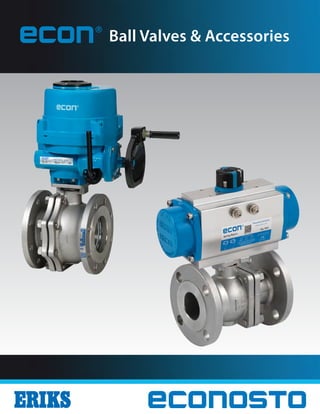
Econ® Products Featured:
Full Port, Flanged Floating Ball Valve with Spring Return
Actuator and Quarter-Turn, Single Acting Smart Positioner.
Econ® Valve Products
Econosto offers a variety of valve and valve related products.
Included are ball valves, butterfly valves, double block and
bleed expanding plug valves, control valves, solenoid valves,
pneumatic and electric valve actuators, valve position limit
switches and analog and digital valve positioners under its
own Econ® label and reputable leading brands. Econosto
is constantly looking to enhance and improve its Econ®
valve related offering and new products are being added
constantly.
Up to Date Product Features
The Econ® brand of products are designed around today’s
standards and expectations that come from various agencies
and customer groups. Throughout its extensive product
offering, Econ® products have added features, which make
them suitable for a wide spectrum of applications.
Proven Quality
Quality is the driving force behind the Econosto and it’s
Econ® brand of products. Econosto has its own teams of
Quality Inspectors stationed strategically close to or within
their manufacturing sites in order to guarantee that their
high quality standards are rigidly adhered to.
An increasing number of customers rely upon Econ®
products because there is a low cost to value ratio. This
means that Econ®products are not only cost competitive
but also perform as well as or better than more expensive
products.
Proven quality since 1892
• Chemical and Petrochemical
• Food and Beverage
• HVAC
• Marine
• Mining
• Oil and Gas
• Original Equipment Manufacturing
• Pulp and Paper
• Semiconductor
• Water and Wastewater
Econosto, part of the ERIKS group, has been offering a wide variety of engineered products since 1892.
By focusing on technical superiority along with guaranteed quality, Econosto’s line of Econ® products are
now sold in most of the major markets throughout the world. Given the strength of the North American
markets, the Econ® brand of ball valves, actuators, and accessories are now being inventoried and sold in
the United States and Canada. Primary amongst the targeted market segments are the following:
4. 4
E10: ASME Class 150
2 Piece, Full Port, Flanged End Ball Valve with Direct Mount Actuation Design
Item Component Material
1 Body A351-CF8M A216-WCB
2 End Cap A351-CF8M A216-WCB
3 Ball 316SS 316SS
4 Ball Seat TFM1600 / PTFE / RTFE TFM1600 / PTFE / RTFE
5 Body Gasket 316 SpiralWound + GRAFOIL 316 SpiralWound + GRAFOIL
6
Bolt A193-B8 A193-B7
Bolt Nut A194-8 A194-2H
7 Stem 316SS 316SS
8 Anti-Static Device 316SS 304SS
9 ThrustWasher PTFE PTFE
10 O-Ring FKM (Viton) FKM (Viton)
11 Stem Packing GRAFOIL GRAFOIL 1 Color: Blue
Note: 8”supplied without operator. Gear operators are available on request.
Item Component Material
12 Bushing 304SS 304SS
13 Gland 316SS 316SS
14 BellevilleWasher 301SS 301SS
15 Retaining Nuts A194-8 A194-8
16 Stop-Lock-Cap 304SS 304SS
17 Lever/Pipe Sleeve1
PlasticVinyl PlasticVinyl
18 Lever 304SS 304SS
19 Locking Device 304SS 304SS
20 Stop Bolt A193-B8 A193-B8
21 T-Handle A53 + Zn Plated A53 + Zn Plated
22 Handle Adapter CF8 CF8
Description
The Econ® E10 Series is a two piece, full port, flanged end
ball valve with ISO 5211 compliant direct mount actuation
pad. The E10 is available in sizes ranging from ½”to 8”with
ASME Class 150 flanges. Valve bodies are made of either
CF8M or WCB with 316SS trim and a variety of seat materials
to choose from.
Features
• Size Range: ½”– 8”
• CF8M and WCB Bodies/316SS Trim
• Fire Safe to API 607 6th Edition
• Built-in ISO 5211 Mounting Pad for Easy Automation
• ATEX 94/9/EC (Ex II 2 G-D EX-c II) Anti-static Design
• TFM 1600 Seat Material (PTFE, RTFE, TFE/SS Options)
• Blow-out Proof Stem
• Pressure Balance Hole in Ball Slot
• TA-Luft (VDI 2440, Sec. 3.3.1.3) Certified Live-loaded
Stem Packing
• Lockable Lever Handle or“T”Handle
• IEC 61508, SIL 2 capable
• 30° & 60° V-Notch Optional Control Ball
Standards
• Design: ASME B16.34, API 608
• Fire Safe: API 607, ISO 10497
• Face to Face: ASME B16.10
• Wall Thickness: ASME B16.34
• End Flange: ASME B16.5
• Inspection and Testing: API 598
Materials of Construction
6. 6
Description
The Econ® E10 Series is a two piece, full port, flanged end ball
valve with ISO 5211 compliant direct mount actuation pad.
The E10 is available in sizes ranging from ½”to 8”with ASME
Class 300 flanges. Valve bodies are made of either CF8M or
WCB with 316SS trim and a variety of seat materials to choose
from.
Features
• Size Range: ½”– 8”
• CF8M and WCB Bodies/316SS Trim
• Fire Safe to API 607 6th Edition
• Built-in ISO 5211 Mounting Pad for Easy Automation
• ATEX 94/9/EC (Ex II 2 G-D EX-c II) Anti-static Design
• TFM 1600 Seat Material (PTFE, RTFE, TFE/SS Options)
• Blow-out Proof Stem
• Pressure Balance Hole in Ball Slot
• TA-Luft (VDI 2440, Sec. 3.3.1.3) Certified Live-loaded Stem
Packing
• Lockable Lever Handle or“T”Handle
• IEC 61508, SIL 2 capable
• 30° & 60° V-Notch Optional Control Ball
Standards
• Design: ASME B16.34, API 608
• Fire Safe: API 607, ISO 10497
• Face to Face: ASME B16.10
• Wall Thickness: ASME B16.34
• End Flange: ASME B16.5
• Inspection and Testing: API 598
E10: ASME Class 300
2 Piece, Full Port, Flanged End Ball Valve with Direct Mount Actuation Design
Item Component Material
1 Body A351-CF8M A216-WCB
2 End Cap A351-CF8M A216-WCB
3 Ball 316SS 316SS
4 Ball Seat TFM1600 / PTFE / RTFE TFM1600 / PTFE / RTFE
5 Body Gasket 316 SpiralWound + GRAFOIL 316 SpiralWound + GRAFOIL
6
Bolt A193-B8 A193-B7
Bolt Nut A194-8 A194-2H
7 Stem 316SS 316SS
8 Anti-Static Device 316SS 304SS
9 ThrustWasher PTFE PTFE
10 O-Ring FKM (Viton) FKM (Viton)
11 Stem Packing GRAFOIL GRAFOIL 1 Color: Blue
Note: 8”supplied without operator. Gear operators are available on request.
Item Component Material
12 Bushing 304SS 304SS
13 Gland 316SS 316SS
14 BellevilleWasher 301SS 301SS
15 Retaining Nuts A194-8 A194-8
16 Stop-Lock-Cap 304SS 304SS
17 Lever/Pipe Sleeve1
PlasticVinyl PlasticVinyl
18 Lever 304SS 304SS
19 Locking Device 304SS 304SS
20 Stop Bolt A193-B8 A193-B8
21 T-Handle A53 + Zn Plated A53 + Zn Plated
22 Handle Adapter CF8 CF8
Materials of Construction
10. 10
Description
The Econ® E15 Series is a one piece, reduced port, flanged
end ball valve with bracket mount actuation pad. The E15 is
available in sizes ranging from ½”to 4”with ASME Class 300
flanges. Valve bodies are made of either CF8M or WCB with
316SS trim and a variety of seat materials to choose from.
Features
• Size Range: ½”- 4”
• CF8M and WCB Bodies/316SS Trim
• Fire Safe Design Approved
• Built-in ISO 5211 Mounting Pad for Easy Automation
• TFM 1600 Seat Material (PTFE, RTFE Options)
• Anti-Static Devices for Ball-Stem-Body
• Blow-out Proof Stem
• Pressure Balance Hole in Ball Slot
Standards
• Design: ASME B16.34, API 608
• Wall Thickness: ASME B16.34
• End Flange: ASME B16.5
• Face to Face: ASME B16.10
• Inspection and Testing: API 598
E15: ASME Class 300
1 Piece, Reduced Port, Flanged End Ball Valve with Bracket Mount Actuation Design
Item Component Material
12 BellevilleWasher 301SS 301SS
13 Retaining Nuts A194-8 A194-8
14 Stop-Lock-Cap 304SS 304SS
15 Lever/Pipe Sleeve3
PlasticVinyl PlasticVinyl
16 Lever 304SS 304SS
17 Locking Device 304SS 304SS
18 Stop Bolt A193-B8 A193-B8
19 T-Handle A53 + Zn Plated A53 + Zn Plated
20 Handle Adapter CF8 CF8
1 Fire safe: GRAFOIL
2 Fire safe: 304SS
3 Color: Blue
Item Component Material
1 Body A351-CF8M A216-WCB
2 End Cap A351-CF8M A216-WCB
3 Ball 316SS 316SS
4 Ball Seat TFM1600 / PTFE / RTFE TFM1600 / PTFE / RTFE
5 Body Gasket1
PTFE PTFE
6 Stem 316SS 316SS
7 Anti-Static Device 316SS 304SS
8 ThrustWasher TFM1600 / PTFE / RTFE TFM1600 / PTFE / RTFE
9 Stem Packing1
PTFE PTFE
10 Bushing2
50% SS + 50% PTFE 50% SS + 50% PTFE
11 Gland 316SS 316SS
Materials of Construction
11. 11
E15: Class 300 - Dimensions in Millimeters (mm)
SIZE Ø d Ø d1 L Ø A T H H1 B Ø h M F J E Ø O Ø N (ISO) K
DN15 12.5 10.0 140.0 95.0 14.7 23.0 74.0 4 16.0 137.0 21.0 9.5 6.3 5 42 (F04) 3/8-24 UNF
DN20 19.0 12.5 152.0 115.0 16.3 23.0 74.0 4 19.0 137.0 21.0 9.5 6.3 5 42 (F04) 3/8-24 UNF
DN25 25.0 17.5 165.0 125.0 17.9 33.5 87.5 4 19.0 170.0 21.5 10.2 9.0 6 50 (F05) 9/16-18 UNF
DN32 32.0 25.0 178.0 135.0 19.5 41.5 95.5 4 19.0 170.0 21.5 10.2 9.0 6 50 (F05) 9/16-18 UNF
DN40 38.0 32.0 190.0 155.0 21.1 47.5 105.0 4 22.3 200.0 32.0 15.0 9.6 8 70 (F07) 5/8-18 UNF
DN50 50.0 38.0 216.0 165.0 22.7 56.5 114.0 8 19.0 200.0 32.0 15.0 9.6 8 70 (F07) 5/8-18 UNF
DN80 76.0 60.3 282.0 210.0 29.0 75.5 142.0 8 22.3 300.0 42.5 18.5 16.0 10 102 (F10) 7/8-14 UNF
DN100 98.0 76.0 305.0 225.0 32.2 96.0 195.0 8 22.3 400.0 55.0 25.0 18.0 10 102 (F10) 1-1/8-12 UNF
E15: Class 300 - Dimensions in Inches (in)
SIZE Ø d Ø d1 L Ø A T H H1 B Ø h M F J E Ø O Ø N (ISO) K
1/2" 0.49 0.39 5.52 3.74 0.58 0.91 2.92 4 0.63 5.40 0.83 0.37 0.25 0.20 1.65 (F04) 3/8-24 UNF
3/4" 0.75 0.49 5.99 4.53 0.64 0.91 2.92 4 0.75 5.40 0.83 0.37 0.25 0.20 1.65 (F04) 3/8-24 UNF
1" 0.99 0.69 6.50 4.93 0.71 1.32 3.45 4 0.75 6.70 0.85 0.40 0.35 0.24 1.97 (F05) 9/16-18 UNF
1-1/4" 1.26 0.99 7.01 5.32 0.77 1.64 3.76 4 0.75 6.70 0.85 0.40 0.35 0.24 1.97 (F05) 9/16-18 UNF
1-1/2" 1.50 1.26 7.49 6.11 0.83 1.87 4.14 4 0.88 7.88 1.26 0.59 0.38 0.32 2.76 (F07) 5/8-18 UNF
2" 1.97 1.50 8.51 6.50 0.89 2.23 4.49 8 0.75 7.88 1.26 0.59 0.38 0.32 2.76 (F07) 5/8-18 UNF
3" 2.99 2.38 11.11 8.27 1.14 2.97 5.59 8 0.88 11.82 1.67 0.73 0.63 0.39 4.02 (F10) 7/8-14 UNF
4" 3.86 2.99 12.02 8.87 1.27 3.78 7.68 8 0.88 15.76 2.17 0.99 0.71 0.39 4.02 (F10) 1-1/8-12 UNF
Dimensions
M
152
17
16
13
1211
10
9
8
7
6
4
3
1
14
B - h
L T
5
J
F
18
4 x Ø O
E
K
Ø N
20
19
15
M
Sizes
3”- 6”
12. 12
E20: 2000 - 1500 WOG
3 Piece Full Port Ball Valve with NPT, Socket or Butt Weld Ends
with Direct Mount Actuation Design
Description
The Econ® E20 Series is a three piece, full port ball valve with
NPT, socket or butt weld ends and ISO 5211 compliant direct
mount actuation pad. The E20 is rated to 2000 WOG in sizes
ranging from ¼”to 1”and to 1500 WOG in sizes ranging from
1-¼”to 2”. Valve bodies are made of either CF8M or WCB with
316SS trim and a variety of seat materials to choose from.
Features
• Size Range: ¼”– 2”
• CF8M and WCB Bodies/316SS Trim
• Fire Safe to API 607 5th Edition
• Built-in ISO 5211 Mounting Pad for Easy Automation
• TFM 4215 Seat Material (TFM 1600 + 15% Carbon Option)
• Anti-Static Devices for Ball-Stem-Body
• Blow-out Proof Stem
• Pressure Balance Hole in Ball Slot
• TA-Luft Design/Approved Live Loaded Stem Packing
• 30° & 60° V-Notch Optional Control Ball
Standards
• Design: ASME B16.34, MSS SP-110, API608
• 2000 WOG for ¼”- 1”
• 1500 WOG for 1-¼”- 2”
• Fire Safe: API 607, ISO 10497
• Wall Thickness: ASME B16.34 Class 800
• Pipe Thread: ASME B1.20.1
• Butt Weld: ASME B16.25 (Ø B2 Sch 80)
• Socket Weld ASME B16.11
• Inspection and Testing: API 598
1 Color: Blue
Item Component Material
1 Body A351-CF8M A216-WCB
2
Cap (Thread) A351-CF8M A216-WCB
Cap (Welding) A351-CF3M A216-WCB
3 Ball 316SS 316SS
4 Ball Seat TFM 4215 TFM 4215
5 Body Gasket GRAFOIL GRAFOIL
6 Bolt A193-B8 A193-B8
7 Bolt Nut A194-8 A194-8
8 BoltWasher 304SS 304SS
9 Stem 316SS 316SS
10 Anti-Static Device 316SS 304SS
11 ThrustWasher PTFE PTFE
Item Component Material
12 O-Ring FKM FKM
13 Stem Packing GRAFOIL GRAFOIL
14 Bushing 304SS 304SS
15 Gland 316SS 316SS
16 BellevilleWasher 301SS 301SS
17 Retaining Nuts A194-8 A194-8
18 Stop-Lock-Cap 304SS 304SS
19 Locking Device 304SS 304SS
20 Lever 304SS 304SS
21 Lever Sleeve1
PlasticVinyl PlasticVinyl
Materials of Construction
14. 14
E30: 2000 - 1500 WOG
2 Piece, Full Port NPT Ball Valve with Direct Mount Actuation Design
1 Fire safe: GRAFOIL
2 Fire safe: 304SS
3 Color: Blue
Description
The Econ® E30 Series is a two piece, full port ball valve with
NPT ends and ISO 5211 compliant direct mount actuation pad.
The E30 is rated to 2000 WOG in sizes ranging from ¼”to 1”
and 1500 WOG in sizes ranging from 1-¼”to 2”. Valve bodies
are made of either CF8M or WCB with 316SS trim and TFM
4215 seats.
Features
• Size Range: ¼”– 2”
• CF8M and WCB Bodies/316SS Trim
• Fire Safe Design Approved
• Built-in ISO 5211 Mounting Pad for Easy Automation
• TFM 4215 Seats
• Anti-Static Devices for Ball-stem-body
• Blow-out Proof Stem
• Pressure Balance Hole in Ball Slot
• TA-Luft Design/Approved Live Loaded Stem Packing
Standards
• Design: ASME B16.34, MSS SP-110
• 2000 WOG for ¼”- 1”
• 1500 WOG for 1¼”- 2”
• Pipe Thread: ASME B1.20.1
• Inspection and Testing: API 598
Item Component Material
1 Body A351-CF8M A216-WCB
2 End Cap A351-CF8M A216-WCB
3 Ball 316SS 316SS
4 Ball Seat TFM4215 /TFM1600 + 15% Carbon TFM4215 /TFM1600 + 15% Carbon
5 Body Gasket1
PTFE PTFE
6 Stem 316SS 316SS
7 Anti-Static Device 316SS 304SS
8 ThrustWasher PTFE PTFE
9 O-Ring FKM FKM
10 Stem Packing1
PTFE PTFE
11 Bushing2
50% SS + 50% PTFE 50% SS + 50% PTFE
12 Gland 316SS 316SS
13 BellevilleWasher 301SS 301SS
14 Retaining Nuts A194-8 A194-8
15 Stop-Lock-Cap 304SS 304SS
16 Lever Sleeve3
PlasticVinyl PlasticVinyl
17 Lever 304SS 304SS
18 Locking Device 304SS 304SS
Materials of Construction
16. 16
E52: 1000 WOG
2 Piece, Full Port NPT Ball Valve
E52: 1000WOG - Dimensions in Millimeters (mm)
SIZE Ø d L H M L2 G
DN8 10.6 58.0 58.0 100.0 12.7 28.5
DN10 12.0 58.0 58.0 100.0 12.7 28.5
DN15 15.0 62.0 58.0 100.0 12.7 28.5
DN20 20.0 72.4 64.0 129.0 22.0 34.8
DN25 25.0 85.0 77.0 156.0 22.0 34.8
DN32 32.0 94.0 83.0 156.0 23.6 38.1
DN40 38.0 105.0 96.0 182.5 23.6 38.1
DN50 50.0 125.0 102.0 182.5 23.6 38.1
Materials of Construction
E52: 1000WOG - Dimensions in Inches (in)
SIZE Ø d L H M L2 G
1/4" 0.42 2.29 2.29 3.94 0.50 1.12
3/8" 0.47 2.29 2.29 3.94 0.50 1.12
1/2" 0.59 2.44 2.29 3.94 0.50 1.12
3/4" 0.79 2.85 2.52 5.08 0.87 1.37
1" 0.99 3.35 3.03 6.15 0.87 1.37
1-1/4" 1.26 3.70 3.27 6.15 0.93 1.50
1-1/2" 1.50 4.14 3.78 7.19 0.93 1.50
2" 1.97 4.92 4.02 7.19 0.93 1.50
Dimensions
Item Component Material
1 Body A351-CF8M A216-WCB
2 Cap A351-CF8M A216-WCB
3 Ball 316SS 316SS
4 Ball Seat PTFE PTFE
5 Stem 316SS 316SS
6 Body Gasket PTFE PTFE
7 ThrustWasher PTFE PTFE
8 V-Ring Packing PTFE PTFE
9 Gland Nut 304SS 304SS
10 StemWasher 304SS 304SS
11 Retaining Nut A194-8 A194-8
12 Locking Device 304SS 304SS
13 Lever 304SS 304SS
14 Lever Sleeve PlasticVinyl PlasticVinyl
Description
The Econ® E52 Series is a two piece, full port ball valve with
NPT ends. The E52 is rated to 1000 WOG and is available in
sizes ranging from ¼”to 2”. Valve bodies are made of either
CF8M or WCB with 316SS trim and PTFE seats.
Features
• Size Range: ¼”– 2”
• CF8M and WCB Bodies/316SS Trim
• Blow-out Proof Stem
• Pressure Balance Hole in Ball Slot
Standards
• Design: ASME B16.34,
• Pipe Thread: ASME B1.20.1
• Inspection and Testing: API 598
1312
11
10
9
8
7
2
14
1
3
5
6
L
4
M
L2
1312
11
10
9
8
7
2
14
1
3
5
6
L
4
M
L2
17. 17
E55: 1000 WOG
1 Piece, Reduced Port NPT Ball Valve
Description
The Econ® E55 Series is a one piece, double reduced port ball
valve with NPT ends. The E55 is rated to 1000 WOG and is
available in sizes ranging from ¼”to 2”. Valve bodies are made
of either 316SS or Carbon Steel with 316SS trim and PTFE
seats.
Features
• Size Range: ¼”– 2”
• Carbon Steel and 316SS Bodies/316SS Trim
• Blow-out Proof Stem
• Pressure Balance Hole in Ball Slot
• Locking Device is Available Upon Request
Standards
• Design: ASME B16.34, MSS SP-110
• Pipe Thread: ASME B1.20.1
• Inspection and Testing: MSS SP-110
E55: 1000WOG - Dimensions in Millimeters (mm)
SIZE Ø d L H M
DN8 5.0 41.5 34.0 70.0
DN10 7.0 47.0 35.0 80.0
DN15 9.1 58.0 44.0 92.0
DN20 12.5 61.0 46.0 92.0
DN25 15.0 73.5 51.0 115.0
DN32 20.0 78.0 58.0 115.0
DN40 25.0 85.0 66.0 127.0
DN50 32.0 102.0 72.0 127.0
Materials of Construction
E55: 1000WOG - Dimensions in Inches (in)
SIZE Ø d L H M
1/4" 0.20 1.64 1.34 2.76
3/8" 0.28 1.85 1.38 3.15
1/2" 0.36 2.29 1.73 3.62
3/4" 0.49 2.40 1.81 3.62
1" 0.59 2.90 2.01 4.53
1-1/4" 0.79 3.07 2.29 4.53
1-1/2" 0.99 3.35 2.60 5.00
2" 1.26 4.02 2.84 5.00
Dimensions
Item Component Material
1 Body A351-CF8M A216-WCB
2 Ball 316SS 316SS
3 End Plug A351-CF8M A216-WCB
4 Ball Seat PTFE PTFE
5 Stem 316SS 316SS
6 Body Gasket PTFE PTFE
7 ThrustWasher PTFE PTFE
8 Stem Packing PTFE PTFE
9 Gland Nut 304SS 304SS
10 StemWasher 304SS 304SS
11 Retaining Nut A194-8 A194-8
12 Lever 304SS 304SS
13 Lever Sleeve PlasticVinyl PlasticVinyl
12 13
8
9
3
10 11
2
5
1
4
6
L
M
7
12 13
8
9
3
10 11
2
5
1
4
6
L
M
7
18. 18
E60: ASME Class 150
3-Way Full Port, Flanged End Ball Valve with Direct Mount Actuation Design
Description
The Econ® E60 Series is a three-way, flanged end ball valve
with ISO 5211 compliant direct mount actuation pad. The E60
is available in sizes ranging from ¼”to 4”with ASME Class 150
flanges. Valve bodies are made of either CF8M or WCB with
316SS trim and a variety of seat materials to choose from.
Features
• Size Range: ½”– 4”
• CF8M and WCB Bodies/316SS Trim
• Built-in ISO 5211 Mounting Pad for Easy Automation
• Anti-Static Devices for Ball-Stem-Body
• Blow-out Proof Stem
• Pressure Balance Hole in Ball Slot
• TA-LUFT Design/Approved Live Loaded Stem Packing
• Locking in Every 90° Increments
• L-Port and T-Port Configurations Available
Standards
• Design: ASME B16.34, API 608
• Flanged Ends: ASME B16.5
• Wall Thickness: ASME B16.34
• Inspection and Testing: API 598
Item Component Material
1 Body A351-CF8M A216-WCB
2 Ball 316SS 316SS
3
Cap A351-CF8M A216-WCB
End Cap A351-CF8M A216-WCB
Bottom Cap A351-CF8M A216-WCB
4 Body Gasket PTFE PTFE
5 Ball Seat TFM1600 / PTFE / RTFE TFM1600 / PTFE / RTFE
6 Bolt A193-B8 A193-B7
7 Stem 316SS 316SS
8 Anti-Static Device 316SS 304SS
9 ThrustWasher PTFE PTFE
10 O-Ring FKM FKM
11 Stem Packing PTFE PTFE
12 Bushing 50% SS + 50% PTFE 50% SS + 50% PTFE
13 Gland 316SS / 304SS 316SS / 304SS
14 BellevilleWasher 301SS 301SS
15 Stop-Lock-Cap 304SS 304SS
16 Retaining Nuts A194-8 A194-8
Materials of Construction
20. 20
E60: ASME Class 300
3-Way Full Port, Flanged End Ball Valve with Direct Mount Actuation Design
Description
The Econ® E60 Series is a three-way, flanged end ball valve
with ISO 5211 compliant direct mount actuation pad. The E60
is available in sizes ranging from ¼”to 4”with ASME Class 300
flanges. Valve bodies are made of either CF8M or WCB with
316SS trim and a variety of seat materials to choose from.
Features
• Size Range: ½”– 4”
• CF8M and WCB Bodies/316SS Trim
• Built-in ISO 5211 Mounting Pad for Easy Automation
• Anti-Static Devices for Ball-Stem-Body
• Blow-out Proof Stem
• Pressure Balance Hole in Ball Slot
• TA-LUFT Design/Approved Live Loaded Stem Packing
• Locking in Every 90° Increments
• L-Port and T-Port Configurations Available
Standards
• Design: ASME B16.34, API 608
• Flanged Ends: ASME B16.5
• Wall Thickness: ASME B16.34
• Inspection and Testing: API 598
Item Component Material
1 Body A351-CF8M A216-WCB
2 Ball 316SS 316SS
3
Cap A351-CF8M A216-WCB
End Cap A351-CF8M A216-WCB
Bottom Cap A351-CF8M A216-WCB
4 Body Gasket PTFE PTFE
5 Ball Seat TFM1600 / PTFE / RTFE TFM1600 / PTFE / RTFE
6 Bolt A193-B8 A193-B7
7 Stem 316SS 316SS
8 Anti-Static Device 316SS 304SS
9 ThrustWasher PTFE PTFE
10 O-Ring FKM FKM
11 Stem Packing PTFE PTFE
12 Bushing 50% SS + 50% PTFE 50% SS + 50% PTFE
13 Gland 316SS / 304SS 316SS / 304SS
14 BellevilleWasher 301SS 301SS
15 Stop-Lock-Cap 304SS 304SS
16 Retaining Nuts A194-8 A194-8
Materials of Construction
22. 22
E70: 1000 WOG
3-Way Full Port NPT Ball Valve with Direct Mount Actuation Design
Description
The Econ® E70 Series is a three-way, full port ball valve with
NPT ends and ISO 5211 compliant direct mount actuation pad.
The E70 is rated to 1000 WOG and is available in sizes ranging
from ¼”to 1-½”. Valve bodies are made of either CF8M or WCB
with 316SS trim and a variety of seat materials to choose from.
Features
• Size Range: ½”– 1-½”
• CF8M and WCB Bodies/316SS Trim
• Built-in ISO 5211 Mounting Pad for Easy Automation
• Anti-Static Devices for Ball-Stem-Body
• Blow-out Proof Stem
• TA-LUFT Design/Approved Live Loaded Stem Packing
• Positive Position Location at 90° Increments
• Locking in Every 90° Increments
• L-Port and T-Port Configurations Available
Standards
• Design: ASME B16.34, MSS SP-110
• Wall Thickness: ASME B16.34 Class 400
• Pipe Thread: ASME B1.20.1
• Inspection and Testing: API 598
Item Component Material
1 Body A351-CF8M A216-WCB
2 End Cap A351-CF8M A216-WCB
3 Ball 316SS 316SS
4 Ball Seat TFM1600 / PTFE / RTFE TFM1600 / PTFE / RTFE
5 Body Gasket PTFE PTFE
6 Stem 316SS 316SS
7 Anti-Static Device 316SS 304SS
8 ThrustWasher PTFE PTFE
9 O-Ring FKM FKM
10 Stem Packing PTFE PTFE
11 Bushing 50% SS + 50% PTFE 50% SS + 50% PTFE
12 Gland 316SS 316SS
13 BellevilleWasher 301SS 301SS
14 Stop-Lock-Cap 304SS 304SS
15 Retaining Nuts A194-8 A194-8
Materials of Construction
23. 23
E70: 1000WOG - Dimensions in Millimeters (mm)
SIZE Ø d L H H1 M F C Ø O1 Ø O2 □E Ø N1 (ISO 1) Ø N2 (ISO 2)
DN15 15 88.0 49.0 77.0 147.0 9.0 44.0 7.0 6.0 9.0 36 (F03) 50 (F05)
DN20 20 108.0 59.5 87.0 176.5 11.0 54.0 7.0 6.0 11.0 42 (F04) 50 (F05)
DN25 25 124.0 63.0 93.0 176.5 11.0 62.0 9.0 6.0 11.0 42 (F04) 70 (F07)
DN32 32 135.0 73.5 103.0 215.0 14.0 67.5 9.0 7.0 14.0 50 (F05) 70 (F07)
DN40 40 164.0 82.8 113.0 215.0 14.0 82.0 9.0 7.0 14.0 50 (F05) 70 (F07)
E70: 1000WOG - Dimensions in Inches (in)
SIZE Ø d L H H1 M F C Ø O1 Ø O2 □E Ø N1 (ISO 1) Ø N2 (ISO 2)
1/2" 0.59 3.47 1.93 3.03 5.79 0.35 1.73 0.28 0.24 0.35 1.42 (F03) 1.97 (F05)
3/4" 0.79 4.25 2.34 3.43 6.96 0.43 2.13 0.28 0.24 0.43 1.65 (F04) 1.97 (F05)
1" 0.98 4.88 2.48 3.66 6.96 0.43 2.44 0.35 0.24 0.43 1.65 (F04) 2.76 (F07)
1-1/4" 1.26 5.32 2.90 4.06 8.47 0.55 2.66 0.35 0.28 0.55 1.97 (F05) 2.76 (F07)
1-1/2" 1.57 6.46 3.26 4.45 8.47 0.55 3.23 0.35 0.28 0.55 1.97 (F05) 2.76 (F07)
Dimensions
4 x Ø O2
4 x Ø O1
ØN2
ØN1
E
C
L
L/2
12
11
10
9
8
7
2
13 1514
4
1
3
6
5
F
L
L/2
M
24. 24
CvValue of BallValve with 30°V-Notch
Series Size
V-
Notch
10%
Open
20%
Open
30%
Open
40%
Open
50%
Open
60%
Open
70%
Open
80%
Open
90%
Open
100%
Open
E10 & E20 1/2” DN15 30° 0.00 0.00 0.16 0.45 0.79 1.36 1.94 3.03 4.21 5.51
E10 & E20 3/4” DN20 30° 0.01 0.01 0.27 0.76 1.32 2.28 3.25 5.10 7.08 9.26
E10 & E20 1” DN25 30° 0.01 0.01 0.42 1.17 2.04 3.52 5.03 7.88 10.94 14.31
E10 & E20 1-1/2” DN40 30° 0.02 0.03 0.95 2.30 4.09 6.63 9.78 13.73 19.13 23.85
E10 & E20 2” DN50 30° 0.00 0.00 2.76 5.70 9.84 15.25 23.02 32.12 42.09 42.18
E10 3” DN80 30° 0.02 1.88 6.10 12.01 20.45 31.24 44.97 61.75 84.75 103.82
E10 4” DN100 30° 0.08 4.41 11.07 21.56 36.32 56.01 81.77 113.91 157.89 176.19
E10 6” DN150 30° 0.03 4.24 17.35 39.34 70.13 108.15 160.02 226.81 301.33 387.09
30° V-Notch Ball
Note:
The data is tested in pure water at ambient temperature. The value above will vary in different mediums.
Cv is the flow coefficient in imperial units. It is defined as the flow rate in US gallons per minute [gpm] of water at a temperature of 60ºF with
a pressure drop across the valve of 1 psi.
60° V-Notch Ball
CvValue of BallValve with 60°V-Notch
Series Size
V-
Notch
10%
Open
20%
Open
30%
Open
40%
Open
50%
Open
60%
Open
70%
Open
80%
Open
90%
Open
100%
Open
E10 & E20 1/2” DN15 60° 0.01 0.01 0.27 0.76 1.33 2.30 3.29 5.15 7.15 9.35
E10 & E20 3/4” DN20 60° 0.01 0.01 0.46 1.29 2.24 3.87 5.52 8.66 12.02 15.72
E10 & E20 1” DN25 60° 0.03 0.17 0.55 1.64 2.76 5.10 7.07 13.01 17.47 24.29
E10 & E20 1-1/2” DN40 60° 0.01 0.01 1.24 3.39 6.27 10.18 15.80 23.64 34.77 45.76
E10 & E20 2” DN50 60° 0.05 0.07 2.59 6.90 12.08 19.63 31.35 47.42 70.82 81.13
E10 3” DN80 60° 0.03 2.24 8.09 17.30 29.89 47.73 73.19 106.87 157.58 190.40
E10 4” DN100 60° 0.07 5.64 15.02 29.85 51.10 83.04 132.96 212.46 340.90 401.72
E10 6” DN150 60° 0.00 6.49 26.68 62.56 112.45 183.18 289.67 437.26 654.69 782.39
Standard Ball
CvValue of BallValve
Size/Series
1/4" 3/8" 1/2” 3/4” 1” 1-1/4” 1-1/2” 2” 3” 4” 5” 6” 8”
DN8 DN10 DN15 DN20 DN25 DN32 DN40 DN50 DN80 DN100 DN125 DN150 DN200
E10 - - 18 36 48 72 120 190 600 1100 1700 2600 4200
E15 - - 15 18 36 48 58 120 450 600 - - -
E20 - - 18 36 48 72 120 190 - - - - -
E30 - - 18 36 48 72 120 190 - - - - -
E52 - - 18 36 48 72 120 190 600 - - - -
E55 - - - - 18 36 48 72 - - - - -
E60 15 15 18 36 45 58 112 224 410 762 - - -
E70 13 13 18 36 45 58 120 - - - - - -
Cv of Ball Valve
Standard and V-Notch Balls
25. 25
KvValue of BallValve
Size/Series
1/4" 3/8" 1/2” 3/4” 1” 1-1/4” 1-1/2” 2” 3” 4” 5” 6” 8”
DN8 DN10 DN15 DN20 DN25 DN32 DN40 DN50 DN80 DN100 DN125 DN150 DN200
E10 - - 15 31 41 62 103 163 514 943 1458 2228 3599
E15 - - 13 15 31 41 50 103 386 514 - - -
E20 - - 15 31 41 62 103 163 - - - - -
E30 - - 15 31 41 62 103 163 - - - - -
E52 - - 15 31 41 62 103 163 514 - - - -
E55 - - - - 15 31 41 62 - - - - -
E60 13 13 15 31 39 50 96 192 351 653 - - -
E70 11 11 15 31 39 50 103 - - - - - -
KvValue of BallValve with 30°V-Notch
Series Size
V-
Notch
10%
Open
20%
Open
30%
Open
40%
Open
50%
Open
60%
Open
70%
Open
80%
Open
90%
Open
100%
Open
E10 & E20 1/2” DN15 30° 0.00 0.00 0.14 0.39 0.68 1.17 1.68 2.62 3.64 4.77
E10 & E20 3/4” DN20 30° 0.01 0.01 0.24 0.65 1.14 1.97 2.82 4.41 6.12 8.01
E10 & E20 1” DN25 30° 0.01 0.01 0.36 1.01 1.76 3.04 4.35 6.82 9.46 12.38
E10 & E20 1-1/2” DN40 30° 0.02 0.03 0.82 1.99 3.54 5.73 8.46 11.88 16.55 20.63
E10 & E20 2” DN50 30° 0.00 0.00 2.39 4.93 8.51 13.19 19.91 27.78 36.41 36.49
E10 3” DN80 30° 0.02 1.63 5.28 10.39 17.69 27.02 38.90 53.41 73.31 89.80
E10 4” DN100 30° 0.07 3.81 9.58 18.65 31.42 48.45 70.73 98.53 136.57 152.40
E10 6” DN150 30° 0.03 3.67 15.01 34.03 60.66 93.55 138.42 196.19 260.65 334.83
KvValue of BallValve with 60°V-Notch
Series Size
V-
Notch
10%
Open
20%
Open
30%
Open
40%
Open
50%
Open
60%
Open
70%
Open
80%
Open
90%
Open
100%
Open
E10 & E20 1/2” DN15 60° 0.01 0.01 0.24 0.66 1.15 1.99 2.84 4.45 6.18 8.09
E10 & E20 3/4” DN20 60° 0.01 0.01 0.40 1.11 1.94 3.34 4.78 7.49 10.39 13.60
E10 & E20 1” DN25 60° 0.03 0.15 0.48 1.42 2.39 4.41 6.12 11.25 15.11 21.01
E10 & E20 1-1/2” DN40 60° 0.01 0.01 1.07 2.93 5.42 8.81 13.67 20.45 30.08 39.58
E10 & E20 2” DN50 60° 0.04 0.06 2.24 5.97 10.45 16.98 27.12 41.02 61.26 70.18
E10 3” DN80 60° 0.03 1.94 7.00 14.96 25.85 41.29 63.31 92.44 136.31 164.70
E10 4” DN100 60° 0.06 4.88 12.99 25.82 44.20 71.83 115.01 183.78 294.88 347.49
E10 6” DN150 60° 0.00 5.61 23.08 54.11 97.27 158.45 250.56 378.23 566.31 676.77
30° V-Notch Ball
60° V-Notch Ball
Standard Ball
Note:
The data is tested in pure water at ambient temperature. The value above will vary in different mediums.
Kv is the flow coefficient in metric units. It is defined as the flow rate in cubic meters per hour [m3/h] of water at a temperature of 16ºC with a
pressure drop across the valve of 1 bar.
Kv of Ball Valve
Standard and V-Notch Balls
28. 28
Seat Performance Capabilities
Pressure Temperature Data
Floating Ball Valves, Class 150/300
Seat Materials: PTFE RTFE TFM1600 EK+PTFE PEEK TFM4215
PTFE is the standard seat material for E52 & E55 Series. TFM1600 is the standard seat material for E10, E15, E60 & E70 Series. TFM4215 is the
standard seat material for E20 and E30 Series.
Body Ratings: Body Ratings of Stainless Steel (SS) - A351-CF8M, Carbon Steel (CS) - A216-WCB or other body materials are referred to ASME B16.34
Full Bore - Sizes 1/2”- 1” Full Bore - Sizes 1-1/4”- 2”
Full Bore - Sizes 3”- 4” Full Bore - Sizes 5”- 8”
Floating Ball Valves, 1000 WOG
Full Bore - Sizes 1/4”- 4”
Floating Ball Valves, 2000 - 1500 WOG
Full Bore - Sizes 1/₄”- 1”(2000 WOG)
Full Bore - Sizes 1-1/₄”- 2”(1500 WOG)
Temperature º
F (º
C)
Pressureinpsi
Pressureinbar
62
55
48
41
34
28
21
14
7
0
-20 0 100 200 300 400 500 600º
F
(-29) (-18) (38) (93) (149) (204) (260) (316)º
C
900
800
700
600
500
400
300
200
100
0
Class 300 CS Body
Class 300 SS Body
Class 150 CS Body
Class 150 SS Body
Temperature º
F (º
C)
Pressureinpsi
Pressureinbar
1000 Max PSI
Sizes 1/4” - 4”
-20 0 100 200 300 400 500 600º
F
(-29) (-18) (38) (93) (149) (204) (260) (316)º
C
1100
1000
900
800
700
600
500
400
300
200
100
0
76
69
62
55
48
41
34
28
21
14
7
0
Temperature º
F (º
C)
Pressureinpsi
Pressureinbar
1500 Max PSI
Sizes 1-1/4” - 2”
2000 Max PSI
Sizes 1/4” - 1”
139
125
111
97
83
69
55
41
28
14
0
2000
1800
1600
1400
1200
1000
800
600
400
200
0
-20 0 100 200 300 400 500 600º
F
(-29) (-18) (38) (93) (149) (204) (260) (316)º
C
Temperature º
F (º
C)
Pressureinpsi
Pressureinbar
Class 150 CS Body
Class 150 SS Body
-20 0 100 200 300 400 500 600º
F
(-29) (-18) (38) (93) (149) (204) (260) (316)º
C
800
700
600
500
400
300
200
100
0
55
48
41
34
28
21
14
7
0
Class 300 CS Body
Class 300 SS Body
Temperature º
F (º
C)
Class 150 CS Body
Class 150 SS Body
-20 0 100 200 300 400 500 600º
F
(-29) (-18) (38) (93) (149) (204) (260) (316)º
C
800
700
600
500
400
300
200
100
0
55
48
41
34
28
21
14
7
0
Pressureinbar
Pressureinpsi
Class 300 CS Body
Class 300 SS Body
Temperature º
F (º
C)
Pressureinbar
Pressureinpsi
Class 300 SS Body
Class 300 CS Body
Class 150 CS Body
Class 150 SS Body
-20 0 100 200 300 400 500 600º
F
(-29) (-18) (38) (93) (149) (204) (260) (316)º
C
800
700
600
500
400
300
200
100
0
55
48
41
34
28
21
14
7
0
PTFE RTFE TFM1600 EK+PTFE PEEK TFM4215Seat Materials:
Class 800 Body
Temperature º
F (º
C)Pressureinpsi
Pressureinbar
62
55
48
41
34
28
21
14
7
0
-20 0 100 200 300 400 500 600º
F
(-29) (-18) (38) (93) (149) (204) (260) (316)º
C
900
800
700
600
500
400
300
200
100
0
Class 300 CS Body
Class 300 SS Body
Class 150 CS Body
Class 150 SS Body
Temperature º
F (º
C)
Pressureinpsi
Pressureinbar
1000 Max PSI
Sizes 1/4” - 4”
-20 0 100 200 300 400 500 600º
F
(-29) (-18) (38) (93) (149) (204) (260) (316)º
C
1100
1000
900
800
700
600
500
400
300
200
100
0
76
69
62
55
48
41
34
28
21
14
7
0
Temperature º
F (º
C)
Pressureinpsi
Pressureinbar
1500 Max PSI
Sizes 1-1/4” - 2”
2000 Max PSI
Sizes 1/4” - 1”
139
125
111
97
83
69
55
41
28
14
0
2000
1800
1600
1400
1200
1000
800
600
400
200
0
-20 0 100 200 300 400 500 600º
F
(-29) (-18) (38) (93) (149) (204) (260) (316)º
C
Temperature º
F (º
C)
Pressureinpsi
Pressureinbar
Class 150 CS Body
Class 150 SS Body
-20 0 100 200 300 400 500 600º
F
(-29) (-18) (38) (93) (149) (204) (260) (316)º
C
800
700
600
500
400
300
200
100
0
55
48
41
34
28
21
14
7
0
Class 300 CS Body
Class 300 SS Body
Temperature º
F (º
C)
Class 150 CS Body
Class 150 SS Body
-20 0 100 200 300 400 500 600º
F
(-29) (-18) (38) (93) (149) (204) (260) (316)º
C
800
700
600
500
400
300
200
100
0
55
48
41
34
28
21
14
7
0
Pressureinbar
Pressureinpsi
Class 300 CS Body
Class 300 SS Body
Temperature º
F (º
C)
Pressureinbar
Pressureinpsi
Class 300 SS Body
Class 300 CS Body
Class 150 CS Body
Class 150 SS Body
-20 0 100 200 300 400 500 600º
F
(-29) (-18) (38) (93) (149) (204) (260) (316)º
C
800
700
600
500
400
300
200
100
0
55
48
41
34
28
21
14
7
0
Class 800 Body
Temperature º
F (º
C)
Pressureinpsi
Pressureinbar
62
55
48
41
34
28
21
14
7
0
-20 0 100 200 300 400 500 600º
F
(-29) (-18) (38) (93) (149) (204) (260) (316)º
C
900
800
700
600
500
400
300
200
100
0
Class 300 CS Body
Class 300 SS Body
Class 150 CS Body
Class 150 SS Body
Temperature º
F (º
C)
Pressureinpsi
Pressureinbar
1000 Max PSI
Sizes 1/4” - 4”
-20 0 100 200 300 400 500 600º
F
(-29) (-18) (38) (93) (149) (204) (260) (316)º
C
1100
1000
900
800
700
600
500
400
300
200
100
0
76
69
62
55
48
41
34
28
21
14
7
0
Temperature º
F (º
C)
Pressureinpsi
Pressureinbar
1500 Max PSI
Sizes 1-1/4” - 2”
2000 Max PSI
Sizes 1/4” - 1”
139
125
111
97
83
69
55
41
28
14
0
2000
1800
1600
1400
1200
1000
800
600
400
200
0
-20 0 100 200 300 400 500 600º
F
(-29) (-18) (38) (93) (149) (204) (260) (316)º
C
Temperature º
F (º
C)
Pressureinpsi
Pressureinbar
Class 150 CS Body
Class 150 SS Body
-20 0 100 200 300 400 500 600º
F
(-29) (-18) (38) (93) (149) (204) (260) (316)º
C
800
700
600
500
400
300
200
100
0
55
48
41
34
28
21
14
7
0
Class 300 CS Body
Class 300 SS Body
Temperature º
F (º
C)
Class 150 CS Body
Class 150 SS Body
-20 0 100 200 300 400 500 600º
F
(-29) (-18) (38) (93) (149) (204) (260) (316)º
C
800
700
600
500
400
300
200
100
0
55
48
41
34
28
21
14
7
0
Pressureinbar
Pressureinpsi
Class 300 CS Body
Class 300 SS Body
Temperature º
F (º
C) Pressureinbar
Pressureinpsi
Class 300 SS Body
Class 300 CS Body
Class 150 CS Body
Class 150 SS Body
-20 0 100 200 300 400 500 600º
F
(-29) (-18) (38) (93) (149) (204) (260) (316)º
C
800
700
600
500
400
300
200
100
0
55
48
41
34
28
21
14
7
0
PTFE RTFE TFM1600 EK+PTFE PEEK TFM4215Seat Materials:
PTFE is the standard seat material for E52 & E55 Series. TFM1600 is the standard seat material for E10, E15, E60 & E70 Series. TFM4215 is the
standard seat material for E20 & E30.
Class 800 Body
Temperature º
F (º
C)
Pressureinpsi
Pressureinbar
62
55
48
41
34
28
21
14
7
0
-20 0 100 200 300 400 500 600º
F
(-29) (-18) (38) (93) (149) (204) (260) (316)º
C
900
800
700
600
500
400
300
200
100
0
Class 300 CS Body
Class 300 SS Body
Class 150 CS Body
Class 150 SS Body
Temperature º
F (º
C)
Pressureinpsi
Pressureinbar
1000 Max PSI
Sizes 1/4” - 4”
-20 0 100 200 300 400 500 600º
F
(-29) (-18) (38) (93) (149) (204) (260) (316)º
C
1100
1000
900
800
700
600
500
400
300
200
100
0
76
69
62
55
48
41
34
28
21
14
7
0
Temperature º
F (º
C)
Pressureinpsi
Pressureinbar
1500 Max PSI
Sizes 1-1/4” - 2”
2000 Max PSI
Sizes 1/4” - 1”
139
125
111
97
83
69
55
41
28
14
0
2000
1800
1600
1400
1200
1000
800
600
400
200
0
-20 0 100 200 300 400 500 600º
F
(-29) (-18) (38) (93) (149) (204) (260) (316)º
C
Temperature º
F (º
C)
Pressureinpsi
Pressureinbar
Class 150 CS Body
Class 150 SS Body
-20 0 100 200 300 400 500 600º
F
(-29) (-18) (38) (93) (149) (204) (260) (316)º
C
800
700
600
500
400
300
200
100
0
55
48
41
34
28
21
14
7
0
Class 300 CS Body
Class 300 SS Body
Temperature º
F (º
C)
Class 150 CS Body
Class 150 SS Body
-20 0 100 200 300 400 500 600º
F
(-29) (-18) (38) (93) (149) (204) (260) (316)º
C
800
700
600
500
400
300
200
100
0
55
48
41
34
28
21
14
7
0
Pressureinbar
Pressureinpsi
Class 300 CS Body
Class 300 SS Body
Temperature º
F (º
C)
Pressureinbar
Pressureinpsi
Class 300 SS Body
Class 300 CS Body
Class 150 CS Body
Class 150 SS Body
-20 0 100 200 300 400 500 600º
F
(-29) (-18) (38) (93) (149) (204) (260) (316)º
C
800
700
600
500
400
300
200
100
0
55
48
41
34
28
21
14
7
0
PTFE RTFE TFM1600 EK+PTFE PEEK TFM4215Seat Materials:
PTFE is the standard seat material for E52 & E55 Series. TFM1600 is the standard seat material for E10, E15, E60 & E70 Series. TFM4215 is the
standard seat material for E20 & E30.
Class 800 Body
Pressureinpsi
90
80
70
60
50
40
30
20
10
Temperature º
F (º
C)
Pressureinpsi
Pressureinbar
1000 Max PSI
Sizes 1/4” - 4”
-20 0 100 200 300 400 500 600º
F
(-29) (-18) (38) (93) (149) (204) (260) (316)º
C
1100
1000
900
800
700
600
500
400
300
200
100
0
76
69
62
55
48
41
34
28
21
14
7
0
Pressureinpsi
200
180
160
140
120
100
80
60
40
20
Temperature º
F (º
C)
Pressureinpsi
Pressureinbar
Class 150 CS Body
Class 150 SS Body
-20 0 100 200 300 400 500 600º
F
(-29) (-18) (38) (93) (149) (204) (260) (316)º
C
800
700
600
500
400
300
200
100
0
55
48
41
34
28
21
14
7
0
Class 300 CS Body
Class 300 SS Body
80
70
60
50
40
30
20
10
Pressureinpsi
Temperature º
F (º
C)
Pressureinbar
Pressureinpsi
Class 300 SS Body
Class 300 CS Body
Class 150 CS Body
Class 150 SS Body
-20 0 100 200 300 400 500 600º
F
(-29) (-18) (38) (93) (149) (204) (260) (316)º
C
800
700
600
500
400
300
200
100
0
55
48
41
34
28
21
14
7
0
PTFE RTFE TFM1600 EK+PTFE PEEK TFM4215Seat Materials:
PTFE is the standard seat material for E52 & E55 Series. TFM1600 is the standa
standard seat material for E20 & E30.
Body Ratings: Body Ratings of Stainless Steel (SS) - ASME A351 CF8M, Carbon Steel (CS) - AS
Temperature º
F (º
C)
Pressureinpsi
Pressureinbar
62
55
48
41
34
28
21
14
7
0
-20 0 100 200 300 400 500 600º
F
(-29) (-18) (38) (93) (149) (204) (260) (316)º
C
900
800
700
600
500
400
300
200
100
0
Class 300 CS Body
Class 300 SS Body
Class 150 CS Body
Class 150 SS Body
Pressureinbar
6
9
2
5
8
1
4
8
1
4
Temperature º
F (º
C)
Pressureinpsi
Pressureinbar
1500 Max PSI
Sizes 1-1/4” - 2”
2000 Max PSI
Sizes 1/4” - 1”
139
125
111
97
83
69
55
41
28
14
0
2000
1800
1600
1400
1200
1000
800
600
400
200
0
-20 0 100 200 300 400 500 600º
F
(-29) (-18) (38) (93) (149) (204) (260) (316)º
C
Pressureinbar
5
8
1
4
8
1
4
Temperature º
F (º
C)
Class 150 CS Body
Class 150 SS Body
-20 0 100 200 300 400 500 600º
F
(-29) (-18) (38) (93) (149) (204) (260) (316)º
C
800
700
600
500
400
300
200
100
0
55
48
41
34
28
21
14
7
0
Pressureinbar
Pressureinpsi
Class 300 CS Body
Class 300 SS Body
Pressureinbar
5
8
1
4
8
1
4
EK TFM4215
TFM1600 is the standard seat material for E10, E15, E60 & E70 Series. TFM4215 is the
Carbon Steel (CS) - ASME A216 WCB or other body materials are referred to ASME B16.34
Class 800 Body
29. 29
Accessories
Stem Extension for Direct Mount Actuation Design
Description
Stem extensions can be mounted on any Econ® valve with
direct mount actuation design. These extensions are made
of stainless steel and have PTFE bushings for smooth
and clearance free operation. A guide ring at the bottom
ensures a solid connection between the extension and the
ball valve.
E
Ø O1
Ø O2
ØN2
ØN1
R
R
H1
H2
HF
H1
H2
HF
4 x Ø O2
4 x Ø O1
ØN2
ØN1
EF
4 x Ø O
F
H
Sizes
1/2”- 2”
Sizes
3”- 4”
Features
• 4” Extension
• Square Stem
• Suited for Manual or Automated Valves
• 316SS
• Live Loaded Packing Arrangement
• Bolts Directly to ISO 5211 Mounting Pad
• Optional Leak Sensing Port
• Allows Direct Actuator Mounting
Direct Mount Stem Extension - Dimensions in Millimeters (mm)
SIZE H H1 H2 F Ø O1 Ø O2 □E Ø N1 (ISO 1) Ø N2 (ISO 2)
DN15 100 12.0 23.0 9.0 6.0 6.0 9.0 36 (F03) 42 (F04)
DN20 100 12.0 23.0 9.0 6.0 6.0 9.0 36 (F03) 42 (F04)
DN25 100 15.0 27.0 11.0 6.0 7.0 11.0 42 (F04) 50 (F05)
DN32 100 15.0 27.0 11.0 6.0 7.0 11.0 42 (F04) 50 (F05)
DN40 100 13.0 30.0 14.0 7.0 9.0 14.0 50 (F05) 70 (F07)
DN50 100 13.0 30.0 14.0 7.0 9.0 14.0 50 (F05) 70 (F07)
DN80 100 24.0 46.0 17.0 9.0 11.0 17.0 70 (F07) 102 (F10)
DN100 100 45.0 52.0 22.0 - 11.0 22.0 - 102 (F10)
Direct Mount Stem Extension - Dimensions in Inches (in)
SIZE H H1 H2 F Ø O1 Ø O2 □E Ø N1 (ISO 1) Ø N2 (ISO 2)
1/2" 3.94 0.47 0.91 0.35 0.24 0.24 0.35 1.42 (F03) 1.65 (F04)
3/4" 3.94 0.47 0.91 0.35 0.24 0.24 0.35 1.42 (F03) 1.65 (F04)
1" 3.94 0.59 1.06 0.43 0.24 0.28 0.43 1.65 (F04) 1.97 (F05)
1-1/4" 3.94 0.59 1.06 0.43 0.24 0.28 0.43 1.65 (F04) 1.97 (F05)
1-1/2" 3.94 0.51 1.18 0.55 0.28 0.35 0.55 1.97 (F05) 2.76 (F07)
2" 3.94 0.51 1.18 0.55 0.28 0.35 0.55 1.97 (F05) 2.76 (F07)
3" 3.94 0.95 1.81 0.67 0.35 0.43 0.67 2.76 (F07) 4.02 (F10)
4" 3.94 1.77 2.05 0.87 - 0.43 0.87 - 4.02 (F10)
Dimensions
30. 30
E
Ø O1
Ø O2
ØN2
ØN1
R
R
H1
H2
HF
H
4 x Ø O
ØN
E
K
H1
H2
HF
Sizes
1/2”- 2”
Sizes
3”- 4”
Description
Econ® stem extensions can be mounted on Econ® ball
valves with bracket mount actuation design (E15 Series).
These extensions are made of stainless steel and have PTFE
bushings for smooth and clearance free operation. A guide
ring at the bottom ensures a solid connection between the
extension and the ball valve.
Accessories
Stem Extension for Bracket Mount Actuation Design
Features
• 4” Extension
• Double D Stem, Gland Packing and Test Connection
• Suited for Manual or Automated Valves
• 316SS
• Live Loaded Packing Arrangement
• Bolts Directly to ISO 5211 Mounting Pad
• Optional Leak Sensing Port
• Allows Direct Actuator Mounting
• Lever Can Be Used
Bracket Mount Stem Extension - Dimensions in Millimeters (mm)
SIZE H H1 H2 F Ø O E Ø N (ISO) K
DN15 100 11.9 23.1 8.9 5.0 6.3 42 (F04) 3/8-24 UNF
DN20 100 11.9 23.1 8.9 5.0 6.3 42 (F04) 3/8-24 UNF
DN25 100 15.0 26.9 10.9 6.0 9.0 50 (F05) 9/16-18 UNF
DN32 100 15.0 26.9 10.9 6.0 9.0 50 (F05) 9/16-18 UNF
DN40 100 13.0 30.0 14.0 8.0 9.6 70 (F07) 5/8-18 UNF
DN50 100 13.0 30.0 14.0 8.0 9.6 70 (F07) 5/8-18 UNF
DN80 100 23.9 46.0 17.0 10.0 16.0 102 (F10) 7/8-14 UNF
DN100 100 45.0 52.1 22.1 10.0 18.0 102 (F10) 1-1/8 -12 UNF
Bracket Mount Stem Extension - Dimensions in Inches (in)
SIZE H H1 H2 F Ø O E Ø N (ISO) K
1/2" 3.94 0.47 0.91 0.35 0.20 0.25 1.65 (F04) 3/8-24 UNF
3/4" 3.94 0.47 0.91 0.35 0.20 0.25 1.65 (F04) 3/8-24 UNF
1" 3.94 0.59 1.06 0.43 0.24 0.35 1.97 (F05) 9/16-18 UNF
1-1/4" 3.94 0.59 1.06 0.43 0.24 0.35 1.97 (F05) 9/16-18 UNF
1-1/2" 3.94 0.51 1.18 0.55 0.32 0.38 2.76 (F07) 5/8-18 UNF
2" 3.94 0.51 1.18 0.55 0.32 0.38 2.76 (F07) 5/8-18 UNF
3" 3.94 0.94 1.81 0.67 0.39 0.63 4.02 (F10) 7/8-14 UNF
4" 3.94 1.77 2.05 0.87 0.39 0.71 4.02 (F10) 1-1/8 -12 UNF
Dimensions
31. 31
Accessories
Quarter Turn Actuators
Rack & Pinion Actuators
• Compact Pneumatic Double Acting or Spring Return
Actuators with Aluminum Housing
• 14 Different Sizes and Variety of Spring Combinations
• Bidirectional Travel Stops
• Output Torques up to 56,831 in-lb (6,421 Nm)
• ATEX, SIL 3, CE Certifications
• Mounting Arrangement and Design Comply to NAMUR
VDI/VDE 3845 and ISO 5211 Standards
• Anti-corrosive Coatings According to EN-15714
Scotch Yoke Actuators
• Modularly Designed Double Acting and Spring Return
Scotch Yoke Actuators in 10 Different Sizes
• Symmetric Yoke for Constant Output Torque up to 2.2
million in-lb (250,000 Nm)
• Fully Protected Against Ingress Water
• Bidirectional Travel Stops
• Designed in Accordance with Pressure Equipment
Directive (PED) 97/23/EC
• ATEX, SIL 3, CE Certifications
Electric Actuator
• Torque Range from 690 to 25,900 in-lb (78 to 2,926 Nm)
• Standard Weatherproof Enclosure (IP67, NEMA 4, 4X & 6)
• Optional Explosion Proof Enclosure (Exd II BT4Gb or II2G)
• Standardized ISO 5211 Mounting Flange
• Open/Close Limit and Torque Switches
• Manual Override
• Self Locking Gear Train
• Mechanical Stops (Adjustable)
• Optional Proportional Control Card
• 110VAC/24VAC/24VDC Power
32. 32
Accessories
Heavy Duty Lever, Smart Positioner and Limit Switches
Heavy Duty Lever
• Option for Econ® Ball Valves with Direct Mount Top Flange
• For Ball Valves Sizes 1/4”to 3”
• Molded Lever for Severe Operating Conditions
• Compatible with Econ® E10, E20, E30, E60 and E70 Series of
Ball Valves
• Figure 6001B
Smart Positioners
• Linear or Rotary Action
• Single or Double Acting
• Push Button Calibration
• 4 - 20 mA Input Control Signal
• -22°F to 185°F (-30°C to 85°C) Ambient Temperature
• LCD Display
• HART Capable
• Linear, Quick Opening, =%, & User Defined Characteristics
• 70 LPM Air Capacity
• IP66 Enclosure
• Figure 3301 through 3304
Limit Switches
• For General Purpose or Explosion Proof Applications
• Micro mechanical Switches or Inductive Switches
• Red and Yellow Visual Position Indicators
• ATEX Certified
• Econ® Brand or Customer Preference
• Compatible with 3-Way Valves Using a Special Visual
Position Indicator
• Figures 79651, 79652 and 79653
33. 33
Ball Valve Ordering Matrix
How to Order
Example: A 2”, Two Piece ASME Class 150, Full Port Ball Valve with Flanged Ends, Carbon Steel Body, Stainless Steel Trim,
TFM1600 Seats, Graphite Packing, NACE Compliant, Fire Safe, Locking Lever Operated is written: 10E10-AR-CSFG-NFC-0200
A
—
B C
—
D E F G
—
H I J
—
K
10E10 A R C S F G N F C 0200
Note:
* Manual operation only (A)
** Full factory lead time may be required for valves with these components.
*** PEEK Seats only available for valves sizes 4”and below.
B Port Configuration
A As Defined (Standard Configuration)
T T-Port
L L-Port
3 30°V-Notch**
6 60° V-Notch**
C End Connection
B BW x BW**
X BWE x BWE
R RF Flange
O FNPT x FNPT
W SW x SW
U FNPT x SW
J RTJ Flange**
D Body Material
C Carbon Steel (A216-WCB)
A Alloy 20**
S Stainless Steel (A351-CF8M)
E Trim
C Carbon Steel
A Alloy 20**
S Stainless Steel
A ConstructionType
10E10 2-PC. ASME-150, Full Port, Flanged
30E10 2-PC. ASME-300, Full Port, Flanged
10E15 1-PC. ASME-150, Reduced Port, Flanged
30E15 1-PC. ASME-300, Reduced Port, Flanged
2WE20 3-PC. 2000WOG, Full Port, NPT/SW/BW/BWE (≤1")
5WE20 3-PC. 1500WOG, Full Port, NPT/SW/BW/BWE (>1")
2WE30 2-PC. 2000WOG, Full Port, NPT (≤1")
5WE30 2-PC. 1500WOG, Full Port, NPT (>1")
1WE52 2-PC. 1000WOG, Full Port, NPT*
1WE55 1-PC. 1000WOG, Double Red. Port, NPT*
10E60 3-Way ASME-150, Full Port, L/T Port, Flanged
30E60 3-Way ASME-300, Full Port, L/T Port, Flanged
1WE70 3-Way 1000WOG, Full Port, L/T Port, NPT
—
—
F Seats
E EK+PTFE**
F TFM1600
G TFM4215
H TFM1600 + 15% Carbon**
P PEEK***
R RTFE**
T PTFE
Z METAL**
V 50%PTFE +50%SS**
G Body Gasket
G Graphite
T PTFE
H NACE
N NACE
O NON-NACE
I Fire Safe
F Fire Safe
O NON-Fire Safe
J Operator
C Locking Lever
L T-Handle
G Gear
K
Port Size
NPS DN
0025 1/4" 8
0038 3/8" 10
0050 1/2" 15
0075 3/4" 20
0100 1" 25
0125 1-1/4" 32
0150 1-1/2" 40
0200 2" 50
0250 2-1/2" 65
0300 3" 80
0400 4" 100
0500 5" 125
0600 6" 150
0800 8" 200
—
—