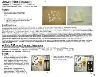
3. 5 Insert the Fan blade (2) to the shaft of
the motor and ilrsfall the whole assembly
onto the base plate. as showrn in figure 18.
Make sure the fan blade can rotate freely.
Connect the motor.s red wire to the spring
connector at position 2 and its black wire
to position 4.
Explanations:
ln step 6 the circuit has a resistor connect in series with the fan, the ourTent must flow through the resistor before reaching the fan motor. In step 7 the resistor is bypassed and
the ourrent flows through the fan without passing through the resistor. YOU can see that the fan spine faster without the resistor because a resistor "resists" the flow Of electnc
ourTent. The higher value Of resistance (measured in ohms) the lower the current will be.
Activitv 5 Diode
ln this activity, you will lean about the diode in a circulit.
Material: -1 Motor(1) -1 Fanblade(2) -1 Fanstand(3) -1Motorholder(4) -1Baseplate(5)
-1 Switchplate(7) -1 Metalplate(8) -4Spnngconnectors(9) -1 Diode(38)
Steps:
1 Followthe step 1-5from activity4,
and connect the diode (38) instead
of resistor. Please notice the colour
of the wire of tl`e diode. The red
wire of the diode is connected to
the spring connector at position 3
and the black wlre to the spring
connector at position 4.
Fig- 20
2. Now insert two AA size batteries according
to the polarity indicated in the battery
compartment (see Fig 5). Press the switch
and see if (he fan is working.
Explanation
In this circuit, an electronlc component called gDiode- is connected in serl.es with the fan,
the electnc current must flow throiigh the diode before reaching the fan motor. The dic)de
+ has the property of allowing the current to flow only in one direction, which maltes it act
like a valve. In step 2 the fan will spln when the switch is pressed because the current
` ; can flowthrough the diodefrom its positlve side (called anode) to its negative side (called
-`| cathode). However, when the diode is connected ln the opposlte direcllon, current cannot
Activitv 6 Make a Liaht
We will make a light cirouit in this activity.
Material: -1 Baseplate(5) -1 LEDnoht(6) -1 Switchplatem
Steps:
1. Follow step 1-2 in Activity 4.
Fig-23
2. Connect the red wlre of the LED light
to the spring connector 2 and the
black wire to the spn'ng connector 4
as shown in Fig. 24. Now insert two
AA size batteries according to the
polarily indicated in the battery
compartment (see Fig. 5). Press the
switch to turn on the LED light.
F,g. 24
Activitv 7 Make a Norse code machine
Material: -1 Baseplate (5) -1 Switchplate (7)
-1 Metal plate (8) -3 Spring connectors (9)
-1 Buzzer (13)
-1 Metal plate(8) -4Spn`ngconnectors(9) -1 Resistor(10)
Explanation
LED (Light Emitting Diode) is an electronic device which ernils light when electnc
current passes through it. It has the same property as the diode that it allows current
to pass through in one direction only. It uses miich less e[ectncity than an ordinary
light bulb. The colour of the LED will depend on the type of material (called
semi¢onductor) used to make it.
Fig.26 4
Steps:
1. Install three spring connectors with the
Swltch plate (7) and Metal plate (8) on
the Base plate (5) as shown in Fig. 26.
Connect the red battery wire to the
spnng connector on the left and black
battery wire to the right as shown.
6. Activitv 11 Make a Motor
Material: -1 Baseplate(5) -1 Motorcoil(16) -1 `Metalpln(17) -2LongseesawLeg(18) -1 Magnet(39) -2Springconnector(9)
Steps:
1. Prepare (he wire and the spring
connector(9). Fix the wires to the
spring connector at about 40mm
from the wire's end, with the wires
pointing upwards as shown in Fig. 50.
2. Put the metal pin(17) through the motor con(16), with the long see saw legs(18)
on each side. (Fig. 51, 52)
3d by the flow of
hen the flow of
imount of electric
i more number of
ma|or adva ntages
strength
iger than a
6dy
4. Place the magnet (39) on the
base plate just under the motor
co,I-(Fig. 55)
F,g-55
5. Install the batteries in the base plate according to the polarities as Indicated in the
battery compartment (see Fig. 5) and flip the coil with your finger The coil will start
to rotate by itself.
Explanation:
Anytime an electric current is passed through a conductor, i( produces a magnetic
field So when electric current passes through the coil (called "armature" of the
motor), it becomes an electromagnet. Assuming that the magnet is sitting with the
North side of it up (it doesn't matter which is up) this is the sequence of events:
you give the motor a spin. When the red and black wires reach the stripped part
of the coil, current flows, forming an electromagnet. Since magnet pole of the
same type repels each other, the North of the electromagnet is repelled by the
North of the magnet. This gives the coil a push, and it spins to a posi(ion where the
wires and the coil break off, and the current ceases to flow. Inertia carries it around
until the stripped portion makes contact again. Now the polarity of the electromagnet
is reversed because the coil is flipped over, and it is attracted towards the magnet.
This gives the coil a pull and i( spins to a position where the coil breaks off again.
Inertia carries the coil to the other side ancl the loop repeats. These attract ancl
repel actions enable the coil to rotate continuously
Activitv 12 Solar Power cell
Material: -1 Baseplate(5) -1 LEDlisht(6) -1 Solarpanel(37) -2Springconnectors(9)
Steps:
1. As shown in Fig 56, install two spring connectors (9) on the base plate. Connect the red wires of the
solar panel (38) and the LED light (6) at one spring connector Similarly, connect the black wires toge(her
at (he other spnng connector. When placed in a room with good lighting, the solar panel will produce
enough electric current to light up the red LED. When the solar panel is getting more light, it produces
more current. Try blocking the panel.with your hand to see wha( happens? Does the LED light become
dimmer or brighter? You can also experiment with different type of light source, for example, sunlight,
fluorescent light or Incandescent light bulb.
Explanation:
Mos( solar cells in the solar panels are made from a crys(alline substance called silicon, one of the Earth's most
common matenals Solar cells ai.e typically made by slicing a large crystal of silicon Into thin wafers and putting
two separate wafers with different electncal properties together, along with wires to enable electrons to travel
between layers. When sunligl`t hits the wafers, electrons naturally travel from one layer to the other through the
wire because of the different properties of each layer, resulting in the release of electricity.
![(€,)
Jezzn8
[
-
fg}¥gJ=e#;:„e.uo}ew
E5F5FT2ngfty
7q'#u!z+
dersMoi|O]
.I
:sdels
¥ase8
I-
:|eHalew
EunERE±±=HE![iAVH=M
-
--
==`±
-==.]=='.
-Lm-."'''|'
I-Tap-I.--..I.-.,'''
a
=E5
..I
-.-LE.
.-
M
I
irjqE=J3.J-
==ri::---:-::-:-::-:
aq
=--
-
a=
Jt"
-
I
:sde]s
:Its
i
-
•,JBt*=-:EE-
i-"-i±ieesseui
iiET5E555
:iii.i.:-:I_---`:--
Em-idx3
-c=
=-I-i-±
EEE=EiiEE=iE
9L
6!]
u!
uMotts
sE
(7)JapioHJolow
8ql
otul
(L)J01ow
eu)uesu|
C
(i;i;;!ei#6if;iiego!INS§es9iioL±e;ei!:,:;:a:;a;gS,L
(9)e)e,d(6°s'e)8J°,}S.'Se¥,)Lj-ap,j:)I:;:};9,u:°°(6cTJpduse,%-uBj(i).8}Bl:zl)e:Opt,¢:B](;).e}e(:)q,°o},I:;;
:§d®]s
E'EiiLii'!'EITnidmmiu!nEa|iE"#
iii6u
®ii|
Ilo
6uuds
eu|
ol
;:'uMd:°ae|:oS,"e:,UMep6£%'.To}8ouLu:uJ,°}'::::::
'u:I;:}:i:e:uJ8:S::,:!;u;zM;:S:}:':qel:;e::8U:E;if:;ui),
:suo!}eueidx]
0'
6,I
0L
6l]uluMous
tr
se(})JepioHjoiow
h
uMoi|s
Se
il/6u
ei/)
o)
ejiM
fuetiBq
xpe|q
pug
ue|
au)
uo
/o|oauuoo
6u!jds
auu°;(u!)ij8;j'iJ;:;u::i;;:e;(;:i;e!::li:I;;I:°!,:i°uiL
:sde]s
(9)e}Eidase8L„.ep,(o6v).S:}°:#U_°°%;J::E;s-uB:8,).e}e':z')E'e3p#e](i).e`B;:)u.°o),'#^i,L:.a.___
¥=jPl==HEHNE!iEHE±E
6Jses::u:i%!;::e}a:d8i§n:o:}:;,a:I;':i:::;'#::::;:::a::;o¥:,i:isio:;aj:i;:i§::§£oa3::1,:;,n;i;;;:¥:3::,;;
:,;n;;i:;:j;;;;;:;:i:;;;;:::::;i:;1;:;;;:i:o;::::;;,;:u;i:j§:;;:i:i::;;ua;I:;;;j;;;i;::i:;;i::a§j:;::;;ju;:¥S
j6zznq
au)
a*eu
oi
imo/IO
.-suo.i]euEidx]
punoleuqus}oeiqoJ'oS:'ue£'ae:::JpPu:je.z
•punos
da8q
^ue
oxeu
::JE::¥:E:!uC'd'J,!o:i£°:';i:#|e:¢^:6ul];I:'
g
9
.6,I
(9
6,i)
:§§iB!Ju3:::;:!:!i:;;::i;e:Li;:i;n,:::j:o:':Jje:a;;:j,
uedlBteup8sodxaau,3s(3)pup"(;;d'eJ°1°euu006UIJdseuwo](data:image/gif;base64,R0lGODlhAQABAIAAAAAAAP///yH5BAEAAAAALAAAAAABAAEAAAIBRAA7)