SlideShare une entreprise Scribd logo
1  sur  25
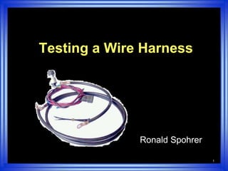
1 Testing a Wire Harness  Ronald Spohrer
2 Overview Two methods of testing a harness using a Multimeter ,[object Object]
  The Voltmeter,[object Object]
4 Testing with an Ohmmeter Test meter to make sure it is working Isolate the component or segment of the circuit that is to be tested Set the meter on the Ohm Scale.  Hint:  Look for the upside-down horse shoe
5 Ohmmeter Remove the current (power/voltage) How: At the source by removing the fuse Turning off the ignition switch, that is if the circuit is controlled by the switch Disconnect from the power source, battery
6 Ohmmeter Connect the probes or leads One at the start or beginning of the circuit and the other at the end If there is continuity (no break) the meter will show zero or low resistance. That is 000 or possibly a few ohms of  resistance depending on the length of wire, connections, and number of devices in line.
7 Ohmmeter If there is a break or open wire the meter will read 1. or UL If there is a break: Keep moving from the end back to the source to isolate the break Check each connection that is in line on that circuit
8
9 Testing with a Voltmeter Test the meter make sure it is working Set the meter to the DCV scale matching the circuits voltage and the vehicles This could be 6v, 12v, 24v, 36v, 48v, 120v.
10 Voltmeter Attach the negative probe, the black lead, to the ground of the vehicle Using the positive probe, the RED lead, Start at the source of the circuit Check for voltage working from the beginning to the end of the of the circuit
11 Voltmeter Example:start at the beginning and progress to the end of the circuit   Battery   Master switch   Ignition switch   Fuse    Connections    The end may be a light
12 Voltmeter Safety Cautions Leave the ground lead (negative lead) connected at all times to a good clean spot When the circuit is energized, it may move a function of the machine Always a possible shock hazard
13 Voltmeter If voltage (power, current) is to and through the light or end use device, but still not working, then most likely the problem is in the ground side of the circuit. If possible, check the ground connections Are they clean, tight, and in good state of repair? Replace the connection or wire as needed
14
15 Testing the Wiring Harness The wiring harness is the main branch with which electrical needs of a machine and its components are met  Wires are commonly sheathed to protect Wires emerge at points along the frame for usage as needed by the machine
16 Wire Harness If a bad wire is found: Individual wires can be repaired or replaced as needed Replace a wire by cutting off the ends of the defective wire and discard Run a new wire along and attach with plastic clips and electrical tape
17 Wire Harness Always use the same size wire.     A smaller wire will not carry the load and in turn will overheat or melt. Do not attempt to thread a new wire into the harness as this may damage other wires in the harness.
18 Wire Harness Electricity needs a complete circuit to follow It will take the path of least resistance When testing a harness one needs to move the harness around when testing with your meter connected
19 Wire harness Test for open wire (broken wire) A-D } infinite resistance A-C } infinite resistance A-B } infinite resistance
20 Wire Harness Tests for short  Bare wire touching frame A-D} zero A-C} infinite A-B} zero if wire intact but grounded A-B} infinite if wire is broken but not touching ground
21 Wire Harness Testing for short, two wires touching A-C} zero A-B} zero A-D} zero if wires touching frame A-D} infinite if wires are not touching frame
22
23 Blown Fuses Not always a short Possible temporary overload    (ice in fan, too many added on devices) Incorrect fuse size Poor contacts - pitted, corroded, excessive resistance
24 Remenber Need to stress check grounds Clean, tight, free of corrosion One major reason, more and more plastic being used Probe at the connection not the wire, every extra hole in wire a place for future problems Personal safety and equipment
25 In review Two methods of testing a harness using a Multimeter The Ohmmeter The Voltmeter

Contenu connexe

Tendances

JOINTS IN ELECTRICAL CONDUCTORS.pptx
JOINTS IN ELECTRICAL CONDUCTORS.pptxJOINTS IN ELECTRICAL CONDUCTORS.pptx
JOINTS IN ELECTRICAL CONDUCTORS.pptxraghuRAGHU56
 
Creo Cabling Solution
Creo Cabling SolutionCreo Cabling Solution
Creo Cabling SolutionCadplatsen AB
 
Unit 01 electrical wiring diagrams
Unit 01 electrical wiring diagramsUnit 01 electrical wiring diagrams
Unit 01 electrical wiring diagramsParneet Chowdhary
 
What are the methods of soldering electronic components
What are the methods of soldering electronic componentsWhat are the methods of soldering electronic components
What are the methods of soldering electronic componentselprocus
 
What Is Magnetic Contactor
What Is Magnetic ContactorWhat Is Magnetic Contactor
What Is Magnetic ContactorEmran Hosain
 
welding process
welding processwelding process
welding processMel Paras
 
Basic Electrical
Basic Electrical Basic Electrical
Basic Electrical ddsshukla
 
Cable joint n end connector
Cable joint n end connectorCable joint n end connector
Cable joint n end connectorBHAGWAN PRASAD
 
Soldering
SolderingSoldering
Solderingcallr
 
Power cables
Power cablesPower cables
Power cablescollege
 
Electrical maintenance-1
Electrical maintenance-1Electrical maintenance-1
Electrical maintenance-1Vijay Raskar
 
Crimping Presentation
Crimping PresentationCrimping Presentation
Crimping PresentationFin1
 
Types of cables
Types of cables Types of cables
Types of cables Nisarg Amin
 
Soldering ppt | use of soldering | application of soldering |
Soldering ppt | use of soldering | application of soldering | Soldering ppt | use of soldering | application of soldering |
Soldering ppt | use of soldering | application of soldering | NITESH POONIA
 

Tendances (20)

JOINTS IN ELECTRICAL CONDUCTORS.pptx
JOINTS IN ELECTRICAL CONDUCTORS.pptxJOINTS IN ELECTRICAL CONDUCTORS.pptx
JOINTS IN ELECTRICAL CONDUCTORS.pptx
 
Creo Cabling Solution
Creo Cabling SolutionCreo Cabling Solution
Creo Cabling Solution
 
SOLDERING
SOLDERINGSOLDERING
SOLDERING
 
Unit 01 electrical wiring diagrams
Unit 01 electrical wiring diagramsUnit 01 electrical wiring diagrams
Unit 01 electrical wiring diagrams
 
Electrical Wiring Practices and Diagrams
Electrical Wiring Practices and DiagramsElectrical Wiring Practices and Diagrams
Electrical Wiring Practices and Diagrams
 
Electrical maintenance
Electrical maintenanceElectrical maintenance
Electrical maintenance
 
What are the methods of soldering electronic components
What are the methods of soldering electronic componentsWhat are the methods of soldering electronic components
What are the methods of soldering electronic components
 
Joints and terminations
Joints and terminationsJoints and terminations
Joints and terminations
 
What Is Magnetic Contactor
What Is Magnetic ContactorWhat Is Magnetic Contactor
What Is Magnetic Contactor
 
welding process
welding processwelding process
welding process
 
Basic Electrical
Basic Electrical Basic Electrical
Basic Electrical
 
Cable joint n end connector
Cable joint n end connectorCable joint n end connector
Cable joint n end connector
 
Types of cables
Types of cablesTypes of cables
Types of cables
 
Soldering
SolderingSoldering
Soldering
 
Power cables
Power cablesPower cables
Power cables
 
Electrical maintenance-1
Electrical maintenance-1Electrical maintenance-1
Electrical maintenance-1
 
Crimping Presentation
Crimping PresentationCrimping Presentation
Crimping Presentation
 
Types of cables
Types of cables Types of cables
Types of cables
 
Electrical workshop
Electrical workshopElectrical workshop
Electrical workshop
 
Soldering ppt | use of soldering | application of soldering |
Soldering ppt | use of soldering | application of soldering | Soldering ppt | use of soldering | application of soldering |
Soldering ppt | use of soldering | application of soldering |
 

Similaire à Wire Harness Test Simple

Lecture24 basiccircuits
Lecture24 basiccircuitsLecture24 basiccircuits
Lecture24 basiccircuitsAlex Klein
 
Aisuphysics
AisuphysicsAisuphysics
AisuphysicsAisu
 
Extech EX330 Mini Multimeter User Manual
Extech EX330 Mini Multimeter User ManualExtech EX330 Mini Multimeter User Manual
Extech EX330 Mini Multimeter User ManualTim Miller
 
Motor testing procedure by javid iqbal sodagar
Motor testing procedure by javid iqbal sodagarMotor testing procedure by javid iqbal sodagar
Motor testing procedure by javid iqbal sodagarjavid iqbal sodagar
 
Chapter 57
Chapter 57Chapter 57
Chapter 57mcfalltj
 
Electronics 01
Electronics 01Electronics 01
Electronics 01snakeaye
 
Basic electrical measuring instruments
Basic electrical measuring instrumentsBasic electrical measuring instruments
Basic electrical measuring instrumentsPramod A
 
Basicelectricalmeasuringinstruments 160111044802
Basicelectricalmeasuringinstruments 160111044802Basicelectricalmeasuringinstruments 160111044802
Basicelectricalmeasuringinstruments 160111044802shivmittal6
 
Rectifier Operations & Maintenance - Don Olson - 2.4.2020
Rectifier Operations & Maintenance - Don Olson - 2.4.2020Rectifier Operations & Maintenance - Don Olson - 2.4.2020
Rectifier Operations & Maintenance - Don Olson - 2.4.2020nacetwincities
 
Electrical Construction Hazards - Presentation Research Material.ppt
Electrical Construction Hazards - Presentation Research Material.pptElectrical Construction Hazards - Presentation Research Material.ppt
Electrical Construction Hazards - Presentation Research Material.pptAhmedElghmati
 
KL1034 Lect2 Electrical wiring.pdf
KL1034 Lect2 Electrical wiring.pdfKL1034 Lect2 Electrical wiring.pdf
KL1034 Lect2 Electrical wiring.pdfSysteDesig
 
3. Introduction of Electrical protective devices (1).pptx
3. Introduction of Electrical protective devices (1).pptx3. Introduction of Electrical protective devices (1).pptx
3. Introduction of Electrical protective devices (1).pptxManilynJabutay1
 
testing-grounding-systems.ppt
testing-grounding-systems.ppttesting-grounding-systems.ppt
testing-grounding-systems.pptBayuAnggoro46
 
Electric Fences with Automated Monitoring System
Electric Fences with Automated Monitoring SystemElectric Fences with Automated Monitoring System
Electric Fences with Automated Monitoring SystemDilshan Jayakody
 

Similaire à Wire Harness Test Simple (20)

Electrical testing
Electrical testingElectrical testing
Electrical testing
 
Lecture24 basiccircuits
Lecture24 basiccircuitsLecture24 basiccircuits
Lecture24 basiccircuits
 
Aisuphysics
AisuphysicsAisuphysics
Aisuphysics
 
Kaise sk 20 22-30 manual
Kaise sk 20 22-30 manualKaise sk 20 22-30 manual
Kaise sk 20 22-30 manual
 
Extech EX330 Mini Multimeter User Manual
Extech EX330 Mini Multimeter User ManualExtech EX330 Mini Multimeter User Manual
Extech EX330 Mini Multimeter User Manual
 
Motor testing procedure by javid iqbal sodagar
Motor testing procedure by javid iqbal sodagarMotor testing procedure by javid iqbal sodagar
Motor testing procedure by javid iqbal sodagar
 
Atv 1000
Atv 1000Atv 1000
Atv 1000
 
Chapter 57
Chapter 57Chapter 57
Chapter 57
 
Electronics 01
Electronics 01Electronics 01
Electronics 01
 
Basic electrical measuring instruments
Basic electrical measuring instrumentsBasic electrical measuring instruments
Basic electrical measuring instruments
 
Basicelectricalmeasuringinstruments 160111044802
Basicelectricalmeasuringinstruments 160111044802Basicelectricalmeasuringinstruments 160111044802
Basicelectricalmeasuringinstruments 160111044802
 
Rectifier Operations & Maintenance - Don Olson - 2.4.2020
Rectifier Operations & Maintenance - Don Olson - 2.4.2020Rectifier Operations & Maintenance - Don Olson - 2.4.2020
Rectifier Operations & Maintenance - Don Olson - 2.4.2020
 
Electrical Construction Hazards - Presentation Research Material.ppt
Electrical Construction Hazards - Presentation Research Material.pptElectrical Construction Hazards - Presentation Research Material.ppt
Electrical Construction Hazards - Presentation Research Material.ppt
 
KL1034 Lect2 Electrical wiring.pdf
KL1034 Lect2 Electrical wiring.pdfKL1034 Lect2 Electrical wiring.pdf
KL1034 Lect2 Electrical wiring.pdf
 
3. Introduction of Electrical protective devices (1).pptx
3. Introduction of Electrical protective devices (1).pptx3. Introduction of Electrical protective devices (1).pptx
3. Introduction of Electrical protective devices (1).pptx
 
Basic electrical lab manual vtu
Basic electrical lab manual vtuBasic electrical lab manual vtu
Basic electrical lab manual vtu
 
basic electrical manual 18 scheme
basic electrical manual 18 schemebasic electrical manual 18 scheme
basic electrical manual 18 scheme
 
Electrical Hazarad
Electrical HazaradElectrical Hazarad
Electrical Hazarad
 
testing-grounding-systems.ppt
testing-grounding-systems.ppttesting-grounding-systems.ppt
testing-grounding-systems.ppt
 
Electric Fences with Automated Monitoring System
Electric Fences with Automated Monitoring SystemElectric Fences with Automated Monitoring System
Electric Fences with Automated Monitoring System
 

Wire Harness Test Simple

  • 1. 1 Testing a Wire Harness Ronald Spohrer
  • 2.
  • 3.
  • 4. 4 Testing with an Ohmmeter Test meter to make sure it is working Isolate the component or segment of the circuit that is to be tested Set the meter on the Ohm Scale. Hint: Look for the upside-down horse shoe
  • 5. 5 Ohmmeter Remove the current (power/voltage) How: At the source by removing the fuse Turning off the ignition switch, that is if the circuit is controlled by the switch Disconnect from the power source, battery
  • 6. 6 Ohmmeter Connect the probes or leads One at the start or beginning of the circuit and the other at the end If there is continuity (no break) the meter will show zero or low resistance. That is 000 or possibly a few ohms of resistance depending on the length of wire, connections, and number of devices in line.
  • 7. 7 Ohmmeter If there is a break or open wire the meter will read 1. or UL If there is a break: Keep moving from the end back to the source to isolate the break Check each connection that is in line on that circuit
  • 8. 8
  • 9. 9 Testing with a Voltmeter Test the meter make sure it is working Set the meter to the DCV scale matching the circuits voltage and the vehicles This could be 6v, 12v, 24v, 36v, 48v, 120v.
  • 10. 10 Voltmeter Attach the negative probe, the black lead, to the ground of the vehicle Using the positive probe, the RED lead, Start at the source of the circuit Check for voltage working from the beginning to the end of the of the circuit
  • 11. 11 Voltmeter Example:start at the beginning and progress to the end of the circuit Battery Master switch Ignition switch Fuse Connections The end may be a light
  • 12. 12 Voltmeter Safety Cautions Leave the ground lead (negative lead) connected at all times to a good clean spot When the circuit is energized, it may move a function of the machine Always a possible shock hazard
  • 13. 13 Voltmeter If voltage (power, current) is to and through the light or end use device, but still not working, then most likely the problem is in the ground side of the circuit. If possible, check the ground connections Are they clean, tight, and in good state of repair? Replace the connection or wire as needed
  • 14. 14
  • 15. 15 Testing the Wiring Harness The wiring harness is the main branch with which electrical needs of a machine and its components are met Wires are commonly sheathed to protect Wires emerge at points along the frame for usage as needed by the machine
  • 16. 16 Wire Harness If a bad wire is found: Individual wires can be repaired or replaced as needed Replace a wire by cutting off the ends of the defective wire and discard Run a new wire along and attach with plastic clips and electrical tape
  • 17. 17 Wire Harness Always use the same size wire. A smaller wire will not carry the load and in turn will overheat or melt. Do not attempt to thread a new wire into the harness as this may damage other wires in the harness.
  • 18. 18 Wire Harness Electricity needs a complete circuit to follow It will take the path of least resistance When testing a harness one needs to move the harness around when testing with your meter connected
  • 19. 19 Wire harness Test for open wire (broken wire) A-D } infinite resistance A-C } infinite resistance A-B } infinite resistance
  • 20. 20 Wire Harness Tests for short Bare wire touching frame A-D} zero A-C} infinite A-B} zero if wire intact but grounded A-B} infinite if wire is broken but not touching ground
  • 21. 21 Wire Harness Testing for short, two wires touching A-C} zero A-B} zero A-D} zero if wires touching frame A-D} infinite if wires are not touching frame
  • 22. 22
  • 23. 23 Blown Fuses Not always a short Possible temporary overload (ice in fan, too many added on devices) Incorrect fuse size Poor contacts - pitted, corroded, excessive resistance
  • 24. 24 Remenber Need to stress check grounds Clean, tight, free of corrosion One major reason, more and more plastic being used Probe at the connection not the wire, every extra hole in wire a place for future problems Personal safety and equipment
  • 25. 25 In review Two methods of testing a harness using a Multimeter The Ohmmeter The Voltmeter