SlideShare une entreprise Scribd logo
1  sur  9
Télécharger pour lire hors ligne
APC                                                                                              APPLICATION NOTE #90
                                                                                                Rack Air Containment application
                                                                                          guidelines and approved configurations
                                                                                                                                                 By Kevin Dunlap


Abstract


The Rack Air Containment System (RACS) is a modular front and rear plenum for use in isolating the supply and return air
between an APC Netshelter® SX rack enclosure and an APC InRow® cooling unit. The containment system is designed to
create a separate environment for air distribution in order to prevent mixing of hot and cold air streams, resulting in a more
predictable cooling pattern. The modular design and ability to retrofit to an existing Netshelter SX rack enables medium to high
density racks to be cooled in an autonomous environment without overcooling the room mixed with lower density loads.


How it works
The most common configuration for rows of racks in the data center is hot/cold aisle design for separating the supply and
return air paths. RACS takes this one step further by containing the return path of hot air exhausted from the IT equipment.
Optionally, the supply path can be contained as well to enhance the distribution path, isolate the rack or for noise attenuation.
Figures 1 and 2 show a rear only and front/rear containment configuration.


                    Figure 1 – RACS (Rear only)                                                                        Figure 2 – RACS (Front and Rear)


                                                   1
____________________________________________________________________________________________________


©2006 American Power Conversion. All rights reserved. No part of this publication may be used, reproduced, photocopied, transmitted,
or stored in any retrieval system of any nature, without the written permission of the copyright owner. www.apc.com     Rev 2010-3
APC                                                                                                                   APPLICATION NOTE


Rear containment only configurations capture the hot exhaust air in a plenum that is also connected to one or more InRow
cooling unit. InRow cooling units are designed to draw air in a back to front pattern. The warm air in the RACS plenum is
drawn to the InRow cooling unit where it is cooled and discharged out the front and back into the room at a room neutral
temperature. The discharge temperature is near, at, or slightly below, room temperature and the selected set point.


Front and rear containment configurations not only capture the hot exhaust air, but also the supply air from the InRow cooling
unit, directing it to the IT equipment inlets in the adjacent rack(s).


Rear only containment is an option because it addresses the warm air discharge from IT racks preventing it from heating up
the surrounding environment. Front only containment is not an option because of the net effect to the inlet side of surrounding
rack enclosures with open fronts. It would also not produce the same energy and capacity gain realized from the warmest
possible air return to the cooling unit.


Benefits of Rack Air Containment


Eliminating mixing of hot/cold air streams in the data center has several benefits over a flooded and mixed environment. The
main benefits from this design are:

                                                              Table 1 – Rack Air Containment Benefits
                                  Benefit                                                         Description / Details
                    Warmer intake temperatures                     Higher temperature differentials, between the entering air and the cooling
                    increase unit capacity                         coil, increase the amount of heat transfer and therefore capacity of the
                                                                   cooling unit. This

                    Predictable cooling                            Removal of heat ensures that the supply temperature has little to no mixing
                                                                   and can be relatively constant and within the ASHRAE recommended
                                                                   guidelines for air delivery.

                    Isolate high density racks                     Allows for mixed density racks to exist in the same environment without
                                                                   overcapacity or overcooling by the perimeter cooling system.

                    Reduction or elimination of                    Elevated entering and discharge temperatures almost guarantees that the
                    moisture removal                               leaving air temperature from the cooling coil will be above dew point. This
                                                                   saves energy on make-up humidification.

                    *Sound Reduction                               Containing the front and/or rear of the rack muffles the noise created by
                                                                   server and cooling unit fans.


             *Using front rack air containment reduces the noise of the InRow unit by 10dba. Tests were conducted on four system
             configurations: 1 ACSC100 and 1 SX Rack with standard doors, 1 ACSC100 and 1 SX Rack with rear RACS only, 1 ACSC100 and
             1 SX Rack with front and rear RACS, and 2 ACSC100 and 1 SX Rack with front and rear RACS. Measurements were taken on all
             four sides at a distance of 1m (3.28 ft) and 1.5m (4.92 ft) from the unit at a height of 1.2 m (3.94 ft).


                                                   2
___________________________________________________________________________________________________

©2006 American Power Conversion. All rights reserved. No part of this publication may be used, reproduced, photocopied, transmitted,
or stored in any retrieval system of any nature, without the written permission of the copyright owner. www.apc.com     Rev 2010-3
APC                                                                                                                              APPLICATION NOTE


Applications and product usage
The use of RACS is not limited to one situation or application in the data center or wiring closet/computer room. In fact, it may
be used as a general purpose cooling solution or as a targeted deployment for a single rack or group of racks. The following
are some common applications for the product.


Isolating Hot Racks
There is a large number of existing data centers, which were designed for densities below 3 kW per rack, in operation today.
Newer IT equipment has pushed well beyond the design density of 3 kW per rack. This stressing of the perimeter or central air
handling cooling system is sometimes compensated for by adding additional capacity (which doesn’t solve the air distribution
problem) or by overcooling the room by running the set point at a lower temperature. Overcooling is a hope strategy the does
not address the hot spot directly but may temper the hot air by mixing in some portion of the overcooled surrounding air.


In this application, in conjunction with InRow cooling unit, RACS provides a targeted cooling solution to higher density racks
without changes to the existing system that was cooling lower density racks sufficiently. Figure 3 shows how a single high-
density rack could be isolated using RACS.

                                                        Figure 3 – Isolated high density rack with RACS
                                                                                                                                                    Single high
                                                                  R
                                                                 R/B-2
                                                                          R
                                                                          R/B-2
                                                                                  R
                                                                                  R/B-2
                                                                                          R
                                                                                          R/B-2
                                                                                                  R
                                                                                                  R/B-2
                                                                                                          R
                                                                                                          R/B-4
                                                                                                                  C
                                                                                                                  ...
                                                                                                                            R
                                                                                                                            R/B-8
                                                                                                                                        C
                                                                                                                                            ...     density rack


                                                                  R       R       R       R       R       R             R           R
                                                                 R/B-2    R/B-2   R/B-2   R/B-2   R/B-2   R/B-2    R/B-2            R/B-2


Single rows
In some cases where hot aisle containment system (HACS) is the preferred method, there may still be a single odd row. This
happens when there are an odd number of rack rows stranding a single row from the ability to use HACS. If such a scenario
occurs, RACS can be used on the odd row to continue the containment architecture using a containment system without
blocking panels to create a shared plenum for air distribution.


                                                        Figure 3 – Odd or single row RACS deployment


                                                   3
___________________________________________________________________________________________________

©2006 American Power Conversion. All rights reserved. No part of this publication may be used, reproduced, photocopied, transmitted,
or stored in any retrieval system of any nature, without the written permission of the copyright owner. www.apc.com     Rev 2010-3
APC                                                                                                                   APPLICATION NOTE


Small Deployments
Small computer rooms and wiring closets are typically not designed for cooling around the clock and through each seasonal
change. Most of the time, these spaces are designed for comfort cooling and may have evening and weekend set backs on
the thermostat to save money. In addition, these environments change from cooling to heat during the winter months.


For this reason, a dedicated cooling system that is separate from the surrounding environment may be required. This
application is ideal for any of the InRow cooling products with RACS and a small number of racks.


Rack Air Containment Components
There are a number of components with the RACS system that allow it to be both retrofitted in the field and modular in nature.
First, since the front containment components are optional, these must be chosen separately. Both rear and front containment
components have the option for separator panels (end caps) to isolate airflow from racks to specific InRow cooling units. While
these are optional, there are specific rules that must be followed to ensure proper air distribution that are discussed later in the
application note.


Table 2 – SKUs and descriptions
          SKU                                        Description
ACCS1000                          Rear Assembly for InRow RC100, SC,
                                  RD100/200

ACCS1001                          Rear Assembly for Netshelter SX 42U
                                  600mm Wide

ACCS1002                          End Caps

ACCS1003                          Front Assembly for InRow RC100, SC,
                                  RD100/200

ACCS1004                          Front Assembly for InRow RP, RC500 and
                                  RD500

ACCS1005                          Front Assembly for Netshelter SX 42U
                                  600mm Wide

ACCS1006                          Rear Assembly for NetShelter SX 42U
                                  750mm wide

ACCS1007                          Front Assembly for NetShelter SX 42U
                                  750mm wide


                                                   4
___________________________________________________________________________________________________

©2006 American Power Conversion. All rights reserved. No part of this publication may be used, reproduced, photocopied, transmitted,
or stored in any retrieval system of any nature, without the written permission of the copyright owner. www.apc.com     Rev 2010-3
APC                                                                                                                     APPLICATION NOTE


Each SKU is designed to be either installed at the same time as the rack and cooling units, or be retrofitted to an existing row-
based cooling environment. Rear and front (optional) rack doors are reconfigured with plexiglass and re-mounted on the new
frame extensions. Figure 4 illustrates the different components and how they are assembled to make the final solution.


                                    Figure 4 – RACS exploded view with InRow RC and Netshelter SX rack

                                                                                                                                                Rear doors
                                                     Rack plenum
                                                                                                                                                from rack
                                                     assembly – rear
                                                     and front
                                                                                                                                                      Rear door from
                                                                                                                                                      cooling unit
                                                                     SX
                                                                     Rack
                     Plenum end
                     cap
                                                                                                                                                 Clear insert
                                                                                                                                                 installed on the
                                                                                                                                                 inside of all
                                                                                                                                                 doors to block
                Front door                                                                                                                       airflow
                from rack


                                                                                                                                       Cooling plenum
                                                                                                             InRow                     assembly – front
                                                                                                             cooling                   and rear
                                                                                                             unit


                                 Front door
                                 from cooling


Product and Component Configuration Options
The ability of the RACS to work with multiple InRow cooling products and the modularity of the parts enables many different
configuration possibilities. However, since each cooling unit has different performance capabilities, there are pre-tested
configurations that have been tested for performance to ensure the proper air distribution within the RACS system. In addition,
while the number of racks is not limited in RACS, the ratio of racks to cooling units and spacing must adhere to approved
configuration layouts and application rules.


Figure 5 represents the tested and approved modules for RACS. Modules are defined as a set of racks and cooling units
paired together in a configuration. Each module has end caps to close off the rear plenum from the surrounding space. End
caps can be removed to join multiple modules together as long as the rules for common plenum are adhered to. These rules
are:

                                                   5
___________________________________________________________________________________________________

©2006 American Power Conversion. All rights reserved. No part of this publication may be used, reproduced, photocopied, transmitted,
or stored in any retrieval system of any nature, without the written permission of the copyright owner. www.apc.com     Rev 2010-3
APC                                                                                                                  APPLICATION NOTE


             1.     The InRow SC may not be used in combination to create a common plenum between modules without consulting
                    the factory.
             2.     Any combination of InRow 300mm wide or InRow 600mm wide units may be used in combination without end
                    caps.
             3.     InRow SC units may not be mixed within the same aisle on a common return plenum with any other types of
                    units.
             4.     InRow RD100 and RD200 units may be mixed on the same common return plenum.
             5.     InRow RC500 and RP500 Units may be mixed within the same aisle on a common return plenum.
             6.     InRow RD500 and RP100 Units may be mixed within the same aisle on a common return plenum.
             7.     Any unit type combinations not specifically allowed in Rules 5, 6, and 7 may not be mixed within the same aisle
                    on a common return plenum.
             8.     InRow RC100 and RD100 configurations highlighted as “Type D” may not be combined with another module
                    when three InRow RC100 or RD100 units would then be adjacent.
             9.     Containment systems using InRow RP should never mix heat of rejection methods (chilled water and air-cooled).


                                                   6
___________________________________________________________________________________________________

©2006 American Power Conversion. All rights reserved. No part of this publication may be used, reproduced, photocopied, transmitted,
or stored in any retrieval system of any nature, without the written permission of the copyright owner. www.apc.com     Rev 2010-3
APC                                                                                                                     APPLICATION NOTE


                                                           Figure 5 – RACS Modules and Module Combination Rules
                          (Air cooled self-contained)

                                                             SC                                 SC                                                      SC

                                                                  SX Rack             SX Rack                                           2+1   SX Rack         SX Rack
                                   InRow SC


                                                             SC             SC

                                                                  SX Rack
                          (Chilled Water, Air-Cooled, or
                            InRow RC100 and RD100


                                                             RC                                 RC                                                      RC

                                                                  SX Rack             SX Rack                                           2+1   SX Rack        SX Rack
                                  Glycol-cooled)


                                                             RC             RC        RC RC                                RC RC
                                                                                                          Type
                                                                  SX Rack                       SX Rack          SX Rack
                                                                                                          D
                          (Chilled Water and Air-Cooled)
                           InRow RP, RC500, and RD500


                                                              RP                                  RP                                                     RP

                                                                      SX Rack         SX Rack                                           2+1   SX Rack            SX Rack


                                                              RP                 RP

                                                                      SX Rack


                                                                                                           Blue dashed lines indicate
                                                                                                           optional front containment


System Controls
InRow products have multiple modes of operation for system control. When placed in a rack air containment system, the
InRow unit must be set to RACS/HACS to ensure that the system is operating properly.

                                                   7
___________________________________________________________________________________________________

©2006 American Power Conversion. All rights reserved. No part of this publication may be used, reproduced, photocopied, transmitted,
or stored in any retrieval system of any nature, without the written permission of the copyright owner. www.apc.com     Rev 2010-3
APC                                                                                                                   APPLICATION NOTE


In addition, the RACS mode has two set points that must be configured. These set points are “supply air temperature” and
“fan speed preference”. In this mode, the cooling set point will have no effect on the operation of the unit. The reason is, the
cooling set point looks at a remote temperature probe in an open-row configuration in order to maintain the inlet temperature to
the adjacent racks. In a RACS configuration, the temperature of the supply air (discharge from the unit) will be the same as
the inlet to the IT equipment because it will not have a chance to mix with the surrounding environment. In addition, the inRow
unit must respond much quicker in RACS mode to ensure that spikes in rack exhaust temperature that occurs over a time
scale of a few seconds is properly neutralized.


While most IT equipment is designed for approximately a 20°F (11.1°C) temperature rise from the inlet to the exhaust (deltaT),
some equipment will require more or less airflow. In cases where the deltaT is known, the fan speed preference setting can be
configured for the desired cfm/kW (l/s per kW).


                                                            Figure 5 – Fan speed preference selection


                         Fan Speed                                 DeltaT                     CFM per                     DeltaT           L/s per
                         Preference                                  °F                         kW                         °C                kW
                  High                                                  10                          325                        5.5           2.56

                  Medium-High                                           15                          215                        8.3           1.69

                  Medium                                                20                          160                       11.1           1.26

                  Medium-Low                                            25                          130                       13.9           1.02

                  Low                                                   30                          105                       16.6           .83


Selection of the fan speed preference should be done by the user using the chart above if the deltaT or CFM/kW (L/s per kW)
is a known. If neither of these two values is known, then a setting of medium is recommended. If it is later determined that the
fan speed is to low or high, it can be easily adjusted.


Choosing a fan speed preference that is too low (higher delta T and lower CFM/kW) could result in the airflow from the servers
to the greater than that of the cooling unit. In this case hot air would be exhausted out the top and bottom of the racks
resulting in an increase in heat load to the rest of the room. Operating with the fan speed preference set higher than
necessary does not have a negative effect on cooling capability, but in general the fans will run faster and the unit will use
more energy. For more information on the controls of the InRow RP, RD, or RC, refer to APC application note #119.


                                                   8
___________________________________________________________________________________________________

©2006 American Power Conversion. All rights reserved. No part of this publication may be used, reproduced, photocopied, transmitted,
or stored in any retrieval system of any nature, without the written permission of the copyright owner. www.apc.com     Rev 2010-3
APC                                                                                                                   APPLICATION NOTE


Conclusions
The rack air containment system is a modular plenum system for improving the predictable architecture of InRow cooling.
Following the guidelines for mating the containment system, system control settings, rack placement and cooling units will
ensure proper air distribution throughout the system.


About the Author:
Kevin Dunlap is Director of Business Strategy for Cooling Solutions at APC. Involved with the power management industry
since 1994, Kevin previously worked for Systems Enhancement Corp., a provider of power management hardware and
software, which APC acquired in 1997. Following the acquisition, Kevin joined APC as a Product Manager for management
cards and then precision cooling solutions following the acquisition of Airflow Company in 2000. Kevin has participated on
numerous power management and cooling panels, as well as on industry consortiums and ASHRAE committees.


                                                   9
___________________________________________________________________________________________________

©2006 American Power Conversion. All rights reserved. No part of this publication may be used, reproduced, photocopied, transmitted,
or stored in any retrieval system of any nature, without the written permission of the copyright owner. www.apc.com     Rev 2010-3

Contenu connexe

Tendances

Data center presentation toi -28022013
Data center presentation   toi -28022013Data center presentation   toi -28022013
Data center presentation toi -28022013
Sanjay Belulkar
 

Tendances (20)

Data Center Cooling Efficiency: Understanding the Science of the 4 Delta T's
Data Center Cooling Efficiency: Understanding the Science of the 4 Delta T'sData Center Cooling Efficiency: Understanding the Science of the 4 Delta T's
Data Center Cooling Efficiency: Understanding the Science of the 4 Delta T's
 
The Science Behind Airflow Management Best Practices
The Science Behind Airflow Management Best PracticesThe Science Behind Airflow Management Best Practices
The Science Behind Airflow Management Best Practices
 
Datwyler data center presentation info tech middle east
Datwyler data center presentation info tech middle eastDatwyler data center presentation info tech middle east
Datwyler data center presentation info tech middle east
 
Data center cooling ahmed abdel-salam (2019)
Data center cooling   ahmed abdel-salam (2019)Data center cooling   ahmed abdel-salam (2019)
Data center cooling ahmed abdel-salam (2019)
 
Energy efficiency data center overview
Energy efficiency data center overviewEnergy efficiency data center overview
Energy efficiency data center overview
 
Simplifying Data Center Design/ Build
Simplifying Data Center Design/ BuildSimplifying Data Center Design/ Build
Simplifying Data Center Design/ Build
 
For Most Data Centers, Liquid and Air Cooling Will Not be Mutually Exclusive
For Most Data Centers, Liquid and Air Cooling Will Not be Mutually ExclusiveFor Most Data Centers, Liquid and Air Cooling Will Not be Mutually Exclusive
For Most Data Centers, Liquid and Air Cooling Will Not be Mutually Exclusive
 
DataCenter:: Infrastructure Presentation
DataCenter:: Infrastructure PresentationDataCenter:: Infrastructure Presentation
DataCenter:: Infrastructure Presentation
 
Gaining Data Center Cooling Efficiency Through Airflow Management
Gaining Data Center Cooling Efficiency Through Airflow ManagementGaining Data Center Cooling Efficiency Through Airflow Management
Gaining Data Center Cooling Efficiency Through Airflow Management
 
ASHRAE 90.4 vs. 90.1 - Five Questions
ASHRAE 90.4 vs. 90.1 - Five QuestionsASHRAE 90.4 vs. 90.1 - Five Questions
ASHRAE 90.4 vs. 90.1 - Five Questions
 
Modular Data Center Design
Modular Data Center DesignModular Data Center Design
Modular Data Center Design
 
Best Practices for Planning your Datacenter
Best Practices for Planning your DatacenterBest Practices for Planning your Datacenter
Best Practices for Planning your Datacenter
 
Data center presentation toi -28022013
Data center presentation   toi -28022013Data center presentation   toi -28022013
Data center presentation toi -28022013
 
Data centers on the Edge
Data centers on the EdgeData centers on the Edge
Data centers on the Edge
 
Implementing Hot and Cold Air Containment in Existing Data Centers
Implementing Hot and Cold Air Containment in Existing Data CentersImplementing Hot and Cold Air Containment in Existing Data Centers
Implementing Hot and Cold Air Containment in Existing Data Centers
 
Data Center Cooling Design - Datacenter-serverroom
Data Center Cooling Design - Datacenter-serverroomData Center Cooling Design - Datacenter-serverroom
Data Center Cooling Design - Datacenter-serverroom
 
Delivering Supermicro Software Defined Storage Solutions with OSNexus QuantaStor
Delivering Supermicro Software Defined Storage Solutions with OSNexus QuantaStorDelivering Supermicro Software Defined Storage Solutions with OSNexus QuantaStor
Delivering Supermicro Software Defined Storage Solutions with OSNexus QuantaStor
 
What Does It Cost to Build a Data Center? (SlideShare)
What Does It Cost to Build a Data Center? (SlideShare)What Does It Cost to Build a Data Center? (SlideShare)
What Does It Cost to Build a Data Center? (SlideShare)
 
Data center hvac
Data center hvacData center hvac
Data center hvac
 
IBM Power9 Features and Specifications
IBM Power9 Features and SpecificationsIBM Power9 Features and Specifications
IBM Power9 Features and Specifications
 

Similaire à APC InRack (RACS) Configurations

Data Centre Efficiency
Data Centre EfficiencyData Centre Efficiency
Data Centre Efficiency
emoclew
 
Cirrascale forest container march 2011
Cirrascale forest container march 2011Cirrascale forest container march 2011
Cirrascale forest container march 2011
Muchamad Jainuri
 
Energy & Environmental Design Approach Speculative Lab Building
Energy & Environmental Design Approach   Speculative Lab BuildingEnergy & Environmental Design Approach   Speculative Lab Building
Energy & Environmental Design Approach Speculative Lab Building
greenbauer1
 
Catologue dan lanh cabero
Catologue dan lanh caberoCatologue dan lanh cabero
Catologue dan lanh cabero
vanthao45
 
AP1000 Reactor
AP1000 ReactorAP1000 Reactor
AP1000 Reactor
myatom
 

Similaire à APC InRack (RACS) Configurations (20)

Data Centre Efficiency
Data Centre EfficiencyData Centre Efficiency
Data Centre Efficiency
 
Cirrascale forest container march 2011
Cirrascale forest container march 2011Cirrascale forest container march 2011
Cirrascale forest container march 2011
 
Tm als f-2011
Tm als f-2011Tm als f-2011
Tm als f-2011
 
Energy & Environmental Design Approach Speculative Lab Building
Energy & Environmental Design Approach   Speculative Lab BuildingEnergy & Environmental Design Approach   Speculative Lab Building
Energy & Environmental Design Approach Speculative Lab Building
 
Catologue dan lanh cabero
Catologue dan lanh caberoCatologue dan lanh cabero
Catologue dan lanh cabero
 
Sb in row-gen.ii-1.0_en
Sb in row-gen.ii-1.0_enSb in row-gen.ii-1.0_en
Sb in row-gen.ii-1.0_en
 
humidity controlled cooler
humidity controlled coolerhumidity controlled cooler
humidity controlled cooler
 
RLKN.pdf
RLKN.pdfRLKN.pdf
RLKN.pdf
 
Active Chilled Beam Technology
Active Chilled Beam TechnologyActive Chilled Beam Technology
Active Chilled Beam Technology
 
CBESS-Sunwoda ABCS (Air-cooling Battery Container System).pdf
CBESS-Sunwoda ABCS (Air-cooling Battery Container System).pdfCBESS-Sunwoda ABCS (Air-cooling Battery Container System).pdf
CBESS-Sunwoda ABCS (Air-cooling Battery Container System).pdf
 
Westinghouse PWR Design Comparison: Gen II versus Gen III
Westinghouse PWR Design Comparison: Gen II versus Gen IIIWestinghouse PWR Design Comparison: Gen II versus Gen III
Westinghouse PWR Design Comparison: Gen II versus Gen III
 
Lasting+ +centre+de+date+-++12mai2010
Lasting+ +centre+de+date+-++12mai2010Lasting+ +centre+de+date+-++12mai2010
Lasting+ +centre+de+date+-++12mai2010
 
Toshiba
ToshibaToshiba
Toshiba
 
Modification of Generator In Electrolux Refrigerator
Modification of Generator In Electrolux RefrigeratorModification of Generator In Electrolux Refrigerator
Modification of Generator In Electrolux Refrigerator
 
Thermal Management of Edge Data Centers
Thermal Management of Edge Data Centers Thermal Management of Edge Data Centers
Thermal Management of Edge Data Centers
 
AP1000 Reactor
AP1000 ReactorAP1000 Reactor
AP1000 Reactor
 
hvac refragration Pipes size and table
hvac refragration Pipes size and tablehvac refragration Pipes size and table
hvac refragration Pipes size and table
 
Review of Design of Air Conditioning System for Commercial and Domestic Appli...
Review of Design of Air Conditioning System for Commercial and Domestic Appli...Review of Design of Air Conditioning System for Commercial and Domestic Appli...
Review of Design of Air Conditioning System for Commercial and Domestic Appli...
 
Crac systems gb
Crac systems gbCrac systems gb
Crac systems gb
 
R y un50_00
R y un50_00R y un50_00
R y un50_00
 

APC InRack (RACS) Configurations

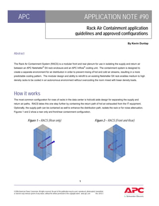
  • 1. APC APPLICATION NOTE #90 Rack Air Containment application guidelines and approved configurations By Kevin Dunlap Abstract The Rack Air Containment System (RACS) is a modular front and rear plenum for use in isolating the supply and return air between an APC Netshelter® SX rack enclosure and an APC InRow® cooling unit. The containment system is designed to create a separate environment for air distribution in order to prevent mixing of hot and cold air streams, resulting in a more predictable cooling pattern. The modular design and ability to retrofit to an existing Netshelter SX rack enables medium to high density racks to be cooled in an autonomous environment without overcooling the room mixed with lower density loads. How it works The most common configuration for rows of racks in the data center is hot/cold aisle design for separating the supply and return air paths. RACS takes this one step further by containing the return path of hot air exhausted from the IT equipment. Optionally, the supply path can be contained as well to enhance the distribution path, isolate the rack or for noise attenuation. Figures 1 and 2 show a rear only and front/rear containment configuration. Figure 1 – RACS (Rear only) Figure 2 – RACS (Front and Rear) 1 ____________________________________________________________________________________________________ ©2006 American Power Conversion. All rights reserved. No part of this publication may be used, reproduced, photocopied, transmitted, or stored in any retrieval system of any nature, without the written permission of the copyright owner. www.apc.com Rev 2010-3
  • 2. APC APPLICATION NOTE Rear containment only configurations capture the hot exhaust air in a plenum that is also connected to one or more InRow cooling unit. InRow cooling units are designed to draw air in a back to front pattern. The warm air in the RACS plenum is drawn to the InRow cooling unit where it is cooled and discharged out the front and back into the room at a room neutral temperature. The discharge temperature is near, at, or slightly below, room temperature and the selected set point. Front and rear containment configurations not only capture the hot exhaust air, but also the supply air from the InRow cooling unit, directing it to the IT equipment inlets in the adjacent rack(s). Rear only containment is an option because it addresses the warm air discharge from IT racks preventing it from heating up the surrounding environment. Front only containment is not an option because of the net effect to the inlet side of surrounding rack enclosures with open fronts. It would also not produce the same energy and capacity gain realized from the warmest possible air return to the cooling unit. Benefits of Rack Air Containment Eliminating mixing of hot/cold air streams in the data center has several benefits over a flooded and mixed environment. The main benefits from this design are: Table 1 – Rack Air Containment Benefits Benefit Description / Details Warmer intake temperatures Higher temperature differentials, between the entering air and the cooling increase unit capacity coil, increase the amount of heat transfer and therefore capacity of the cooling unit. This Predictable cooling Removal of heat ensures that the supply temperature has little to no mixing and can be relatively constant and within the ASHRAE recommended guidelines for air delivery. Isolate high density racks Allows for mixed density racks to exist in the same environment without overcapacity or overcooling by the perimeter cooling system. Reduction or elimination of Elevated entering and discharge temperatures almost guarantees that the moisture removal leaving air temperature from the cooling coil will be above dew point. This saves energy on make-up humidification. *Sound Reduction Containing the front and/or rear of the rack muffles the noise created by server and cooling unit fans. *Using front rack air containment reduces the noise of the InRow unit by 10dba. Tests were conducted on four system configurations: 1 ACSC100 and 1 SX Rack with standard doors, 1 ACSC100 and 1 SX Rack with rear RACS only, 1 ACSC100 and 1 SX Rack with front and rear RACS, and 2 ACSC100 and 1 SX Rack with front and rear RACS. Measurements were taken on all four sides at a distance of 1m (3.28 ft) and 1.5m (4.92 ft) from the unit at a height of 1.2 m (3.94 ft). 2 ___________________________________________________________________________________________________ ©2006 American Power Conversion. All rights reserved. No part of this publication may be used, reproduced, photocopied, transmitted, or stored in any retrieval system of any nature, without the written permission of the copyright owner. www.apc.com Rev 2010-3
  • 3. APC APPLICATION NOTE Applications and product usage The use of RACS is not limited to one situation or application in the data center or wiring closet/computer room. In fact, it may be used as a general purpose cooling solution or as a targeted deployment for a single rack or group of racks. The following are some common applications for the product. Isolating Hot Racks There is a large number of existing data centers, which were designed for densities below 3 kW per rack, in operation today. Newer IT equipment has pushed well beyond the design density of 3 kW per rack. This stressing of the perimeter or central air handling cooling system is sometimes compensated for by adding additional capacity (which doesn’t solve the air distribution problem) or by overcooling the room by running the set point at a lower temperature. Overcooling is a hope strategy the does not address the hot spot directly but may temper the hot air by mixing in some portion of the overcooled surrounding air. In this application, in conjunction with InRow cooling unit, RACS provides a targeted cooling solution to higher density racks without changes to the existing system that was cooling lower density racks sufficiently. Figure 3 shows how a single high- density rack could be isolated using RACS. Figure 3 – Isolated high density rack with RACS Single high R R/B-2 R R/B-2 R R/B-2 R R/B-2 R R/B-2 R R/B-4 C ... R R/B-8 C ... density rack R R R R R R R R R/B-2 R/B-2 R/B-2 R/B-2 R/B-2 R/B-2 R/B-2 R/B-2 Single rows In some cases where hot aisle containment system (HACS) is the preferred method, there may still be a single odd row. This happens when there are an odd number of rack rows stranding a single row from the ability to use HACS. If such a scenario occurs, RACS can be used on the odd row to continue the containment architecture using a containment system without blocking panels to create a shared plenum for air distribution. Figure 3 – Odd or single row RACS deployment 3 ___________________________________________________________________________________________________ ©2006 American Power Conversion. All rights reserved. No part of this publication may be used, reproduced, photocopied, transmitted, or stored in any retrieval system of any nature, without the written permission of the copyright owner. www.apc.com Rev 2010-3
  • 4. APC APPLICATION NOTE Small Deployments Small computer rooms and wiring closets are typically not designed for cooling around the clock and through each seasonal change. Most of the time, these spaces are designed for comfort cooling and may have evening and weekend set backs on the thermostat to save money. In addition, these environments change from cooling to heat during the winter months. For this reason, a dedicated cooling system that is separate from the surrounding environment may be required. This application is ideal for any of the InRow cooling products with RACS and a small number of racks. Rack Air Containment Components There are a number of components with the RACS system that allow it to be both retrofitted in the field and modular in nature. First, since the front containment components are optional, these must be chosen separately. Both rear and front containment components have the option for separator panels (end caps) to isolate airflow from racks to specific InRow cooling units. While these are optional, there are specific rules that must be followed to ensure proper air distribution that are discussed later in the application note. Table 2 – SKUs and descriptions SKU Description ACCS1000 Rear Assembly for InRow RC100, SC, RD100/200 ACCS1001 Rear Assembly for Netshelter SX 42U 600mm Wide ACCS1002 End Caps ACCS1003 Front Assembly for InRow RC100, SC, RD100/200 ACCS1004 Front Assembly for InRow RP, RC500 and RD500 ACCS1005 Front Assembly for Netshelter SX 42U 600mm Wide ACCS1006 Rear Assembly for NetShelter SX 42U 750mm wide ACCS1007 Front Assembly for NetShelter SX 42U 750mm wide 4 ___________________________________________________________________________________________________ ©2006 American Power Conversion. All rights reserved. No part of this publication may be used, reproduced, photocopied, transmitted, or stored in any retrieval system of any nature, without the written permission of the copyright owner. www.apc.com Rev 2010-3
  • 5. APC APPLICATION NOTE Each SKU is designed to be either installed at the same time as the rack and cooling units, or be retrofitted to an existing row- based cooling environment. Rear and front (optional) rack doors are reconfigured with plexiglass and re-mounted on the new frame extensions. Figure 4 illustrates the different components and how they are assembled to make the final solution. Figure 4 – RACS exploded view with InRow RC and Netshelter SX rack Rear doors Rack plenum from rack assembly – rear and front Rear door from cooling unit SX Rack Plenum end cap Clear insert installed on the inside of all doors to block Front door airflow from rack Cooling plenum InRow assembly – front cooling and rear unit Front door from cooling Product and Component Configuration Options The ability of the RACS to work with multiple InRow cooling products and the modularity of the parts enables many different configuration possibilities. However, since each cooling unit has different performance capabilities, there are pre-tested configurations that have been tested for performance to ensure the proper air distribution within the RACS system. In addition, while the number of racks is not limited in RACS, the ratio of racks to cooling units and spacing must adhere to approved configuration layouts and application rules. Figure 5 represents the tested and approved modules for RACS. Modules are defined as a set of racks and cooling units paired together in a configuration. Each module has end caps to close off the rear plenum from the surrounding space. End caps can be removed to join multiple modules together as long as the rules for common plenum are adhered to. These rules are: 5 ___________________________________________________________________________________________________ ©2006 American Power Conversion. All rights reserved. No part of this publication may be used, reproduced, photocopied, transmitted, or stored in any retrieval system of any nature, without the written permission of the copyright owner. www.apc.com Rev 2010-3
  • 6. APC APPLICATION NOTE 1. The InRow SC may not be used in combination to create a common plenum between modules without consulting the factory. 2. Any combination of InRow 300mm wide or InRow 600mm wide units may be used in combination without end caps. 3. InRow SC units may not be mixed within the same aisle on a common return plenum with any other types of units. 4. InRow RD100 and RD200 units may be mixed on the same common return plenum. 5. InRow RC500 and RP500 Units may be mixed within the same aisle on a common return plenum. 6. InRow RD500 and RP100 Units may be mixed within the same aisle on a common return plenum. 7. Any unit type combinations not specifically allowed in Rules 5, 6, and 7 may not be mixed within the same aisle on a common return plenum. 8. InRow RC100 and RD100 configurations highlighted as “Type D” may not be combined with another module when three InRow RC100 or RD100 units would then be adjacent. 9. Containment systems using InRow RP should never mix heat of rejection methods (chilled water and air-cooled). 6 ___________________________________________________________________________________________________ ©2006 American Power Conversion. All rights reserved. No part of this publication may be used, reproduced, photocopied, transmitted, or stored in any retrieval system of any nature, without the written permission of the copyright owner. www.apc.com Rev 2010-3
  • 7. APC APPLICATION NOTE Figure 5 – RACS Modules and Module Combination Rules (Air cooled self-contained) SC SC SC SX Rack SX Rack 2+1 SX Rack SX Rack InRow SC SC SC SX Rack (Chilled Water, Air-Cooled, or InRow RC100 and RD100 RC RC RC SX Rack SX Rack 2+1 SX Rack SX Rack Glycol-cooled) RC RC RC RC RC RC Type SX Rack SX Rack SX Rack D (Chilled Water and Air-Cooled) InRow RP, RC500, and RD500 RP RP RP SX Rack SX Rack 2+1 SX Rack SX Rack RP RP SX Rack Blue dashed lines indicate optional front containment System Controls InRow products have multiple modes of operation for system control. When placed in a rack air containment system, the InRow unit must be set to RACS/HACS to ensure that the system is operating properly. 7 ___________________________________________________________________________________________________ ©2006 American Power Conversion. All rights reserved. No part of this publication may be used, reproduced, photocopied, transmitted, or stored in any retrieval system of any nature, without the written permission of the copyright owner. www.apc.com Rev 2010-3
  • 8. APC APPLICATION NOTE In addition, the RACS mode has two set points that must be configured. These set points are “supply air temperature” and “fan speed preference”. In this mode, the cooling set point will have no effect on the operation of the unit. The reason is, the cooling set point looks at a remote temperature probe in an open-row configuration in order to maintain the inlet temperature to the adjacent racks. In a RACS configuration, the temperature of the supply air (discharge from the unit) will be the same as the inlet to the IT equipment because it will not have a chance to mix with the surrounding environment. In addition, the inRow unit must respond much quicker in RACS mode to ensure that spikes in rack exhaust temperature that occurs over a time scale of a few seconds is properly neutralized. While most IT equipment is designed for approximately a 20°F (11.1°C) temperature rise from the inlet to the exhaust (deltaT), some equipment will require more or less airflow. In cases where the deltaT is known, the fan speed preference setting can be configured for the desired cfm/kW (l/s per kW). Figure 5 – Fan speed preference selection Fan Speed DeltaT CFM per DeltaT L/s per Preference °F kW °C kW High 10 325 5.5 2.56 Medium-High 15 215 8.3 1.69 Medium 20 160 11.1 1.26 Medium-Low 25 130 13.9 1.02 Low 30 105 16.6 .83 Selection of the fan speed preference should be done by the user using the chart above if the deltaT or CFM/kW (L/s per kW) is a known. If neither of these two values is known, then a setting of medium is recommended. If it is later determined that the fan speed is to low or high, it can be easily adjusted. Choosing a fan speed preference that is too low (higher delta T and lower CFM/kW) could result in the airflow from the servers to the greater than that of the cooling unit. In this case hot air would be exhausted out the top and bottom of the racks resulting in an increase in heat load to the rest of the room. Operating with the fan speed preference set higher than necessary does not have a negative effect on cooling capability, but in general the fans will run faster and the unit will use more energy. For more information on the controls of the InRow RP, RD, or RC, refer to APC application note #119. 8 ___________________________________________________________________________________________________ ©2006 American Power Conversion. All rights reserved. No part of this publication may be used, reproduced, photocopied, transmitted, or stored in any retrieval system of any nature, without the written permission of the copyright owner. www.apc.com Rev 2010-3
  • 9. APC APPLICATION NOTE Conclusions The rack air containment system is a modular plenum system for improving the predictable architecture of InRow cooling. Following the guidelines for mating the containment system, system control settings, rack placement and cooling units will ensure proper air distribution throughout the system. About the Author: Kevin Dunlap is Director of Business Strategy for Cooling Solutions at APC. Involved with the power management industry since 1994, Kevin previously worked for Systems Enhancement Corp., a provider of power management hardware and software, which APC acquired in 1997. Following the acquisition, Kevin joined APC as a Product Manager for management cards and then precision cooling solutions following the acquisition of Airflow Company in 2000. Kevin has participated on numerous power management and cooling panels, as well as on industry consortiums and ASHRAE committees. 9 ___________________________________________________________________________________________________ ©2006 American Power Conversion. All rights reserved. No part of this publication may be used, reproduced, photocopied, transmitted, or stored in any retrieval system of any nature, without the written permission of the copyright owner. www.apc.com Rev 2010-3