

Recommandé
Contenu connexe
Tendances
Tendances (20)
Similaire à Plc operation part 2
Similaire à Plc operation part 2 (20)
Plus de Sakshi Vashist
Plus de Sakshi Vashist (20)
Dernier
Dernier (20)
Plc operation part 2
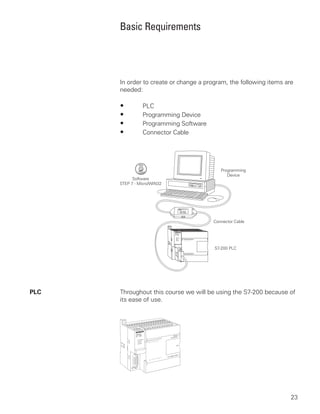
- 1. Basic Requirements In order to create or change a program, the following items are needed: • PLC • Programming Device • Programming Software • Connector Cable PLC Throughout this course we will be using the S7-200 because of its ease of use. 23
- 2. Programming Devices The program is created in a programming device (PG) and then transferred to the PLC. The program for the S7-200 can be created using a dedicated Siemens SIMATIC S7 programming device, such as a PG 720 (not shown) or PG 740, if STEP 7 Micro/WIN software is installed. A personal computer (PC), with STEP 7 Micro/WIN installed, can also be used as a programming device with the S7-200. 24
- 3. Software A software program is required in order to tell the PLC what instructions it must follow. Programming software is typically PLC specific. A software package for one PLC, or one family of PLCs, such as the S7 family, would not be useful on other PLCs. The S7-200 uses a Windows based software program called STEP 7-Micro/WIN32. The PG 720 and PG 740 have STEP 7 software pre-installed. Micro/WIN32 is installed on a personal computer in a similar manner to any other computer software. Connector Cables PPI Connector cables are required to transfer data from the (Point-to-Point Interface) programming device to the PLC. Communication can only take place when the two devices speak the same language or protocol. Communication between a Siemens programming device and the S7-200 is referred to as PPI protocol (point- to- point interface). An appropriate cable is required for a programming device such as a PG 720 or PG 740. The S7-200 uses a 9-pin, D-connector. This is a straight-through serial device that is compatible with Siemens programming devices (MPI port) and is a standard connector for other serial interfaces. SF/DIAG Programming Device Cable 25
- 4. A special cable is needed when a personal computer is used as a programming device. Two versions of this cable are available. One version, called an RS-232/PPI Multi-Master Cable, connects a personal computer’s RS-232 interface to the PLC’s RS-485 connector. The other version, called a USB/PPI Multi-Master Cable, connects a personal computer’s USB interface to the PLC’s RS-485 connector. 26
- 5. Review 2 1. A switch or a pushbutton is a ____________ input. 2. A lamp or a solenoid is an example of a ___________ output. 3. The ____________ makes decisions and executes control instructions based on the input signals. 4. ____________ ____________ is a PLC programming language that uses components resembling elements used in a line diagram. 5. A ____________ consists of one or more instructions that accomplish a task. 6. Memory is divided into three areas: ____________ , ____________ , and ____________ ____________ space. 7. When talking about computer or PLC memory, 1K refers to ____________ bits, bytes, or words. 8. Software that is placed in hardware is called ____________ . 9. Which of the following is not required when creating or changing a PLC program? a. PLC b. Programming Device c. Programming Software d. Connector Cable e. Printer 10. An RS-232/PPI Multi-Master cable or a USB/PPI-Multi- Master cable may be used to connect a personal computer to the PLC’s ____________ connector. 27
- 6. S7-200 Micro PLCs The S7-200 Micro PLC is the smallest member of the SIMATIC S7 family of programmable controllers. The central processing unit (CPU) is internal to the PLC. Inputs and outputs (I/O) are the system control points. Inputs monitor field devices, such as switches and sensors. Outputs control other devices, such as motors and pumps. The programming port is the connection to the programming device. S7-200 Models There are five S7-200 CPU types: CPU 221, CPU 222, CPU 224, CPU 224XP and CPU 226 and two power supply configurations , for each type. Model Description Power Supply Input Types Output Types 221 DC/DC/DC 20.4-28.8 VDC 6 DC 4 DC 221 AC/DC/Relay 85-264 VAC, 47-63 Hz 6 DC 4 Relay 222 DC/DC/DC 20.4-28.8 VDC 8 DC 6 DC 222 AC/DC/Relay 85-264 VAC, 47-63 Hz 8 DC 6 Relay 224 DC/DC/DC 20.4-28.8 VDC 14 DC 10 DC 224 AC/DC/Relay 85-264 VAC, 47-63 Hz 14 DC 10 Relay 224XP DC/DC/DC 20.4-28.8 VDC 14 DC, 2 Analog 10 DC, 1 Analog 224XP AC/DC/Relay 85-264 VAC, 47-63 Hz 14 DC, 2 Analog 10 Relay, 1 Analog 226 DC/DC/DC 20.4-28.8 VDC 24 DC 16 DC 226 AC/DC/Relay 85-264 VAC, 47-63 Hz 24 DC 16 Relay The model description indicates the type of CPU, the power supply, the type of input, and the type of output. 28
- 7. S7-200 Features The S7-200 family includes a wide variety of CPUs and features. This variety provides a range of features to aid in designing a cost-effective automation solution. The following table provides a summary of the major features, many of which will be covered in this course. Feature CPU 221 CPU 222 CPU 224 CPU 224XP CPU 226 Memory Program (with run mode edit) 4096 Bytes 4096 Bytes 8192 Bytes 12288 Bytes 16384 Bytes Program (w/o run mode edit) 4096 Bytes 4096 Bytes 12288 Bytes 16384 Bytes 24576 Bytes User Data 2048 Bytes 2048 Bytes 8192 Bytes 10240 Bytes 10240 Bytes Memory Type EEPROM EEPROM EEPROM EEPROM EEPROM Memory Cartridge EEPROM EEPROM EEPROM EEPROM EEPROM Data Backup (super cap) 50 Hours 50 Hours 100 Hours 100 Hours 100 Hours Data Backup (opt. battery) 200 Days 200 Days 200 Days 200 Days 200 Days I/O Local Digital I/O 6 In/4 Out 8 In/6 Out 14 In/10 Out 14 In/10 Out 24 In/16 Out Local Analog I/O None None None 2 In/1 Out None Max Expansion Modules None 2 7 7 7 Instructions Boolean Execution Speed 0.22 µs/Inst. 0.22 µs/Inst. 0.22 µs/Inst. 0.22 µs/Inst. 0.22 µs/Inst. Internal Relays 256 256 256 256 256 Counters 256 256 256 256 256 TImers 256 256 256 256 256 Sequential Control Relays 256 256 256 256 256 For/Next Loops Yes Yes Yes Yes Yes Integer Math (+-*/) Yes Yes Yes Yes Yes Floating-Point Math (+-*/) Yes Yes Yes Yes Yes Enhanced Features 4 (30 KHz), High-Speed Counters 4 (30 KHz) 4 (30 KHz) 6 (30 KHz) 6 (30 KHz) 2 (200 KHz) Analog Adjustments 1 1 2 2 2 Pulse Outputs (DC) 2 (20 KHz) 2 (20 KHz) 2 (20 KHz) 2 (100 KHz) 2 (20 KHz) Timed Interrupts 2 (1 - 255ms) 2 (1 - 255ms) 2 (1 - 255ms) 2 (1 - 255ms) 2 (1 - 255ms) Edge Interrupts 4 4 4 4 4 Real-Time Clock Optional Optional Built-In Built-In Built-In Password Protection Yes Yes Yes Yes Yes Communications Number of Ports 1 (RS-485) 1 (RS-485) 1 (RS-485) 2 (RS-485) 2 (RS-485) PPI, MPI, PPI, MPI, PPI, MPI, PPI, MPI, PPI, MPI, Protocols Supported Freeport Freeport Freeport Freeport Freeport Peer-to-Peer PPI Master Mode (NETR/NETW) (NETR/NETW) (NETR/NETW) (NETR/NETW) (NETR/NETW) 29
- 8. Mode Switch and When the mode switch is in the RUN position the CPU is in the Analog Adjustment run mode and executing the program. When the mode switch is in the STOP position the CPU is stopped. When the mode switch is in the TERM position the programming device can select the operating mode. The analog adjustment is used to increase or decrease values stored in special memory. These values can be used to update the value of a timer or counter, or can be used to set limits. Optional Cartridge The S7-200 supports an optional memory cartridge that provides a portable EEPROM storage for your program. The cartridge can be used to copy a program from one S7-200 PLC to a like S7-200 PLC. In addition, two other cartridges are available. A real-time clock with battery is available for use on the CPU 221 and CPU 222. The battery provides up to 200 days of data retention time in the event of a power loss. The CPU 224, CPU 224XP and CPU 226 have a real-time clock built in. Another cartridge is available with a battery only. SF/DIAG 30
- 9. Expansion Modules The S7-200 PLCs are expandable. Expansion modules contain additional inputs and outputs. These are connected to the base unit using a ribbon connector. The ribbon connector is protected by a cover on the base unit. Side-by-side mounting completely encloses and protects the ribbon connector. 31
- 10. Available Expansion The CPU 221 comes with 6 digital inputs and 4 digital outputs. These are not expandable. The CPU 222 comes with 8 digital inputs and 6 digital outputs and will accept up to 2 expansion modules. The CPU 224 and CPU 224XP come with 14 digital inputs and 10 digital outputs and will accept up to 7 expansion modules. The S7-226 comes with 24 digital inputs and 16 digital outputs and will accept up to 7 expansion modules. 6 Inputs, 4 Outputs CPU221 No Expansion Modules (EM) 8 Inputs, 6 Outputs CPU222 EM EM Up to 2 Expansion Modules 14 Inputs, 10 Outputs CPU224 EM EM EM EM EM EM EM Up to 7 Expansion Modules 14 Inputs, 10 Outputs CPU224XP EM EM EM EM EM EM EM 2 Analog In, 1 Analog Out Up to 7 Expansion Modules 24 Inputs, 16 Outputs CPU226 EM EM EM EM EM EM EM Up to 7 Expansion Modules Status Indicators The CPU status indicators reflect the current mode of CPU operation. When the CPU is in the RUN mode, the green RUN indicator is lit. When the CPU is in the STOP mode, the yellow STOP indicator is lit. The System Fault/Diagnostic (SF/DIAG) indicator turns red for a system fault and yellow to indicate certain diagnostic conditions. The I/O status indicators represent the On or Off status of corresponding inputs and outputs. For example, when the CPU senses an input is on, the corresponding green indicator is lit. 32
- 11. Installing The S7-200 can be installed in one of two ways. A DIN clip allows installation on a standard DIN rail. The DIN clip snaps open to allow installation and snaps closed to secure the unit on the rail. The S7-200 can also be panel mounted using installation holes located behind the access covers. External Power Supply An S7-200 can be connected to either a 24 VDC or a 120/230 Sources VAC power supply depending on the CPU. An S7-200 DC/DC/ DC would be connected to a 24 VDC power supply. 24 VDC Power Supply An S7-200 AC/DC/Relay would be connected to a 120 or 230 VAC power supply. Neutral Ground Line 33
- 12. I/O Numbering S7-200 inputs and outputs are labeled at the wiring terminations and next to the status indicators. These alphanumeric symbols identify the I/O address to which a device is connected. This address is used by the CPU to determine which input is present and which output needs to be turned on or off. I designates a discrete input and Q designates a discrete output. The first number identifies the byte, the second number identifies the bit. Input I0.0, for example, is byte 0, bit 0. I0.0 = Byte 0, Bit 0 I0.1 = Byte 0, Bit 1 I1.0 = Byte 1, Bit 0 I1.1 = Byte 1, Bit 1 The following table identifies the input and output designations. Inputs Input devices, such as switches, pushbuttons, and other sensor devices are connected to the terminal strip under the bottom cover of the PLC. Input Devices Connected Here Pushbutton Switch 34
- 13. Input Simulator A convenient method of testing a program is to wire toggle switches to the inputs. Input simulators with prewired toggle switches are available for the S7-200s. Switches are wired between the 24 VDC power supply (L+) and the inputs. For example, the switch on the far left is wired between the first input (0.0) and L+. When the switch is closed, 24 VDC is applied to the input. This is referred to as a logic 1. When the switch is open, 0 VDC is applied to the input. This is referred to as a logic 0. Outputs Output devices, such as relays, are connected to the terminal strip under the top cover of the PLC. When testing a program, it is not necessary to connect output devices. The LED status indicators signal if an output is active. Light Relay From Input Power Supply Output Devices Wired Here 35
- 14. Optional Connector An optional fan-out connector allows for field wiring connections to remain fixed when removing or replacing a CPU 221 or CPU 222. The appropriate connector slides into either the input, output, or expansion module terminals. Removable Terminal Strip The CPU 224, CPU 224XP and CPU 226 do not have an optional , fan-out connector. Instead, the terminal strips are removable. This allows the field wiring connections to remain fixed when removing or replacing the PLC. 36
- 15. Super Capacitor A super capacitor, so named because of its ability to maintain a charge for a long period of time, protects data stored in RAM in the event of a power loss. The RAM memory is typically backed up on the CPU 221 and CPU 222 for 50 hours, and on the CPU 224, CPU 224 XP and CPU 226 for 100 hours. , Reference Manual The SIMATIC S7-200 Programmable Controller System Manual provides complete information on installing and programming the S7-200 PLCs. 37
- 16. Review 3 1. The five models of S7-200 are ____________ , ____________ , ____________ , ____________, and ____________ . 2. Which of the following is not available on an CPU 221? a. Mode Switch b. Expansion Port c. Programming Port d. Status Indicators 3. A CPU 222 can have a maximum of ____________ expansion modules and a CPU 224 can have a maximum of ____________ expansion modules. 4. A CPU 222 has ____________ DC inputs and ____________ DC outputs without expansion modules. 5. A CPU 224 has ____________ DC inputs and ____________ DC outputs without expansion modules. 6. The fourth output of an S7-200 would be labeled ____________ . 7. S7-200 can be panel mounted or installed on a ____________ rail. 38
- 17. Connecting External Devices TD200 The S7-200 programming port can be used to communicate with a variety of external devices. One such device is the TD200 text display unit. The TD200 displays messages read from the S7-200, allows adjustment of designated program variables, provides the ability to force, and permits setting of the time and date. The TD200 can be connected to an external power supply or receive its power from the S7-200. SF/DIAG Programming PPI Protocol Device Cable Freeport Mode The programming port has a mode called freeport mode. Freeport mode allows connectivity to various intelligent sensing devices such as a bar code reader. Bar-Code Decoder Bar-Code Reader Programming Port Freeport Mode RS-485 to RS-232 Interface 39
- 18. Printer Freeport mode can also be used to connect to a non-SIMATIC printer. Freeport Mode Programming Port Connecting Cable Serial to Parallel Converter Interconnection It is possible to use one programming device to address multiple S7-200 devices on the same communication cable. A total of 31 units can be interconnected without a repeater. IBM or IBM Compatible PC S7-200 S7-200 S7-200 PPI Interconnection 40
- 19. Programming a PLC STEP 7-Micro/WIN32 is the program software used with the S7-200 PLC to create the PLC operating program. STEP 7 consists of a number of instructions that must be arranged in a logical order to obtain the desired PLC operation. These instructions are divided into three groups: standard instructions, special instructions, and high-speed instructions. Standard Instructions Standard instructions consists of instructions that are found in most programs. Standard instructions include: timer, counter, math, logical, increment/decrement/invert, move, and block instructions. Special Instructions Special instructions are used to manipulate data. Special instructions include: shift, table, find, conversion, for/next, and real-time instructions. High-Speed Instructions High-speed instructions allow for events and interrupts to occur independent of the PLC scan time. These include high-speed counters, interrupts, output, and transmit instructions. It is not the purpose of this text to explain all of the instructions and capabilities. A few of the more common instructions necessary for a basic understanding of PLC operation will be discussed. PLC operation is limited only by the hardware capabilities and the ingenuity of the person programming it. Refer to the SIMATIC S7-200 Programmable Controller System Manual for detailed information concerning these instructions. 41
- 20. Micro/WIN32 The programming software can be run Off-line or On-line. Off- line programming allows the user to edit the ladder diagram and perform a number of maintenance tasks. The PLC does not need to be connected to the programming device in this mode. On-line programming requires the PLC to be connected to the programming device. In this mode program changes are downloaded to the PLC. In addition, status of the input/output elements can be monitored. The CPU can be started, stopped, or reset. Symbols In order to understand the instructions a PLC is to carry out, an understanding of the language is necessary. The language of PLC ladder logic consists of a commonly used set of symbols that represent control components and instructions. Contacts One of the most confusing aspects of PLC programming for first-time users is the relationship between the device that controls a status bit and the programming function that uses a status bit. Two of the most common programming functions are the normally open (NO) contact and the normally closed (NC) contact. Symbolically, power flows through these contacts when they are closed. The normally open contact (NO) is closed when the input or output status bit controlling the contact is 1. The normally closed contact (NC) is closed when the input or output status bit controlling the contact is 0. 42
- 21. Coils Coils represent relays that are energized when power flows to them. When a coil is energized, it causes a corresponding output to turn on by changing the state of the status bit controlling that output to 1. That same output status bit may be used to control normally open and normally closed contacts elsewhere in the program. Boxes Boxes represent various instructions or functions that are executed when power flows to the box. Typical box functions are timers, counters, and math operations. Entering Elements Control elements are entered in the ladder diagram by positioning the cursor and selecting the element from a lists. In the following example the cursor has been placed in the position to the right of I0.2. A coil was selected from a pull- down list and inserted in this position. Network 1 I0.0 I0.1 Q0.0 Network 2 Cursor I0.2 43
- 22. An AND Operation Each rung or network on a ladder represents a logic operation. The following programming example demonstrates an AND operation. Two contact closures and one output coil are placed on network 1. They were assigned addresses I0.0, I0.1, and Q0.0. Note that in the statement list a new logic operation always begins with a load instruction (LD). In this example I0.0 (input 1) and (A in the statement list) I0.1 (input 2) must be true in order for output Q0.0 (output 1) to be true. It can also be seen that I0.0 and I0.1 must be true for Q0.0 to be true by looking at the function block diagram representation. Another way to see how an AND function works is with a Boolean logic diagram. In Boolean logic an AND gate is represented by a number of inputs on the left side. In this case there are two inputs. The output is represented on the right side. It can be seen from the table that both inputs must be a logic 1 in order for the output to be a logic 1. And (A) Function And (A) Function Input 1 I0.0 Output 1 Q0.0 Input 2 I0.1 Input 1 Input 2 Output 1 I0.0 I0.1 Q0.0 0 0 0 0 0 0 0 1 0 0 1 0 1 0 0 1 0 0 1 1 1 1 1 1 44