
Recommandé
Contenu connexe
Similaire à Av 10 ramp tester
Similaire à Av 10 ramp tester (20)
Dernier
Dernier (20)
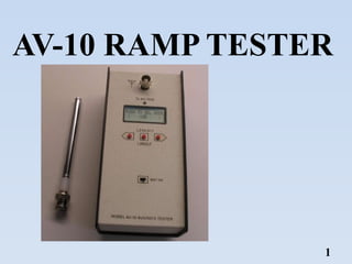
Av 10 ramp tester
- 2. CONTENT • INTRODUCTION • SPECIFICATION • SUB ASSEMBLIES OF THE AV-10 RAMP TESTER • AV-10 RAMP TESTER • BATTERY REPLACEMENT • TESTING PROCEDURE (VOR,DME,ADF,ILS,TRANSPONDER) • QUESTION 2
- 3. INTRODUCTION OF THE AV-10 RAMP TESTER 3 The AV-10 Ramp Tester is a test equipment. It is used for the checking the Serviceability status of the avionic equipment in the aircraft. The AV-10 Ramp tester provides test functions for VOR, ILS, ADF, DME and Transponder in MI 17 Helicopters.
- 4. 4 SPECIFICATION Power Supply : 6V (1.5V x 4) Battery Size : AA battery (Qty 04) Operating Temperature Range : -20 to +50 °C Storage Temperature Range : -30 to +70 °C Accuracy of All Carrier Frequencies Basic accuracy : +/- 2.5 PPM plus +/-1.0 PPM aging per year. Variation over temperature = +/- 2 PPM over -20 to +50 °C range. Transmit power : 0.25mW Output Power (dbm -power ratio in decibel) ADF = -12 +/-3 dbm ILS GS = -17 +/-3 dbm VOR = -10 +/-3 dbm ILS Localizer = -10 +/-3 dbm ILS MKR = -15 +/-3 dbm DME = -12 +/-3 dbm TXPDR = -12 +/-3 dbm Accuracy VOR radial accuracy : +/- 1 deg ILS localizer DDM accuracy : +/- 15% ILS glide slope DDM accuracy : +/- 15% DME accuracy : +/- 0.1NM
- 5. 5 SUB ASSEMBLIES OF THE AV-10 RAMP TESTER AV-10 Ramp Tester Antenna AA Battery Pack
- 6. 6 AV-10 RAMP TESTER ON/OFF Switch Control Button Display Indicator (blue) Antenna Connector
- 7. 7 BATTERY REPLACEMENT The AV-10 is powered by (4) AA batteries. Heavy duty alkaline or equivalent should provide over 2 hours of continuous operation. To replace the batteries, remove the four rubber feet using a Phillips Screw driver to access the battery holder. Make sure battery negative goes to spring end of holder positions. Before long term storage it's best to remove the batteries to prevent battery leakage damage. Also promptly replace expended batteries.
- 8. 8 TESTING PROCEDURE The transmit power of the AV-10 is very low .approximately 0.25 mW , so you will need to be close (15-40 ft) to the aircraft for most testing. The power was designed to be very small so that the likelihood of interference is low and so that the sensitivity of the aircraft receivers can be checked. when using the AV-10,be sure that you do not interfere with any other aircraft or ATC system. A good method to limit possible interference is to test inside of a metal hangar when testing the ILS marker beacon, the AV-10 antenna will need to be within a inch or two of the aircraft marker antenna. The aircraft marker receiver was intentionally designed with 100 times lower sensitivity than your other receivers so that it only picks up the marker when the plane is close to the marker transmitter. Make sure the aircraft marker receiver is set to high sensitivity if available. The ADF receiver may also require the AV-10 to be close due to the poor antenna match at its low frequencies other test modes (TXPDR, DME, VOR) allow at least 3 foot spacing between the AV-10 and the aircraft antennas
- 9. 9 VOR test Degree form VOR station : 00, 450, 900, 1350, 1800, 2250, 2700, 3150 Carrier frequencies : 108.0Mhz, 110.2Mhz, 112.4Mhz, 113.6Mhz Station ID tone : 1020 Hz on/off beep When the AV-15 is powered on it does its self test . Then the display shows PUSH TO SEL MODE < VOR > To activate the VOR test mode press & release the center key. The display will show PUSH TO SEL FREQ < 108.0 > When the desired frequency is displayed then select it with the center key. The display shows <- VOR RADIAL -> 45 deg FROM The AV-10 now is transmitting the VOR signal with 450 phase shift between the 9960 subcarrier reference and the 30 Hz AM modulation. The NAV OBS should show 450 FROM or 225 TO the station. By using the left or right keys other radials can be selected at 450 intervals. When finished with VOR testing, press and hold the center key down for about 2 seconds until the blue LED blinks, then release the key to return to start of main menu.
- 10. ILS test 10 carrier frequency 108.1 or 110.3 MHz station ID 1020 Hz center, 1/2 and full deflection right and left no 150Hz or no 90Hz modulation to check NAV flag Use right or left keys to move to PUSH TO SEL MODE < ILS > Select with center key. To do localizer, select it with center key. Use left right keys to select carrier frequency, then the display shows SEL LOC DDM DDM=0 or CENTER NAV indicator should show a centered needle for the ILS localizer DDM = difference in depth of modulation SEL LOC DDM 1/2 RIGHT .078 • Your NAV indicator should show half deflection, DDM=.078. • Use the left right keys to select half, full deflection left and right as well as having only 90 or 150 Hz modulation. • When you are finished do a long center key push to return to main menu
- 11. 11 GLIDE SLOPE test 108.1 - 334.7 or 110.3 - 335.0 MHz carrier frequency. Center, 1/2 and Full deflection up and down No 150Hz or no 90Hz modulation to check flag. No ID tone as normal Use right or left keys to move to PUSH TO SEL MODE < GLIDE > Select with center key. To do GLIDE SLOPE , select it with center key. Use left right keys to select carrier frequency, then the display shows SEL LOC DDM DDM=0 or CENTER When you are finished do a long center key push to return to main menu
- 12. 12 MARKER BEACON test A 75MHz AM modulated RF signal.. The AV-10 provides OUTER, MIDD LE, and INNER marker beacon signals. need to place the AV-10 antenna within a few inches of the marker antenna. PUSH TO SEL MODE < ILS > PUSH TO SEL MODE < MARKER BEACON > MARKER TYPE < OUTER MARKER > MARKER TYPE < MIDDLE MARKER > MARKER TYPE < INNER MARKER >
- 13. 13 DME test. It Generates a fixed 20NM distance signal to the DME PUSH TO SEL MODE < DME > Use right or left keys PUSH TO SEL FREQ < 108.0 > DME ACTIVE 20NM INTERO/SEC= 0 Select with center key. Select with right or left keys .
- 14. 14 ADF test. PUSH TO SEL MODE < ADF-NDB > PUSH TO SEL FREQ < 400.0 KHz > AM NDB Beacon < 400.0 KHz > Use right or left keys Select with center key. Select with right or left keys . Provides AM modulated low frequency signals (400.0KHz,450.0KHz,650.0KHz,1200.0KHz)
- 15. 15 TRANSPONDER Test PUSH TO SEL MODE < VOR > < TRANSPONDER > SEL TXPDR MODE MODE A SQUAWK After turning on the AV10 and waiting for the self test to run, the display will read push left push button so that display line 2 reads now push center button to select transponder testing. The display will now show we press the center button to select it. The display will show SIDELOBE SUPPRES NO SLS P2 OFF ?
- 16. 16 AV-10 Ramp Tester Calibration The calibration is done yearly to insure that the unit is still functioning within specifications. HP8568B spectrum analyzer.
- 17. 17