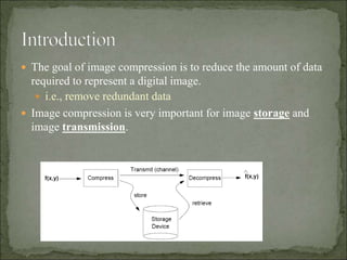
1. The goal of image compression is to reduce the amount of data
required to represent a digital image.
i.e., remove redundant data
Image compression is very important for image storage and
image transmission.
4. Coding redundancy
Interpixel redundancy
Psychovisual redundancy
The role of compression is to reduce one or more of these
redundancy types.
5. A compression ratio of 10 (10:1) means that the first data set has
10 information carrying units (say, bits) for every 1 unit in the
second (compressed) data set.
6. Data compression can be achieved by encoding the data using
an appropriate encoding scheme.
Elements of an encoding scheme:
Code: a list of symbols (letters, numbers, bits etc.)
Code word: a sequence of symbols used to represent a piece
of information or an event (e.g., gray levels)
Word length: number of symbols in each code word
7. To avoid coding redundancy, codes should be selected
according to the probabilities of the events.
Idea: Variable Length Coding
Assign fewer symbols (bits) to the more probable events
(i.e., gray levels in our case)
8. Focus on gray value images
Histogram shows the frequency of occurrence of a particular gray
level
Normalize the histogram and convert to a pdf representation – let rk
be the random variable
pr(rk) = nk/n ;
k = 0, 1,2 …., L-1, where L is the number of gray level values.
Nk is the no. of times that kth gray level appears in the image.
N= total no. of pixels in the image.
l(rk) = number of bits to represent rk
Lavg = k=0 to L-1 l(rk) pr(rk) = average number of bits to encode
one pixel.
9. the histogram calculations
where p(rk) is the probability of a pixel to have a
certain value rk
If the number of bits used to represent rk is l(rk), then
)()((
)(
)(
1
0
L
k
kkav
kk
k
rprlL
n
n
n
rh
rp
10.
11.
12. When the value of pixel can be obtained from its neighboring
pixel, then the redundancy is called interpixel redundancy.
Much of the visual contribution of a single pixel to an image is
redundant, it could have been guessed on the basis of its
neighbors.
In order to reduce redundancy in 2D arrays
We can convert them into more efficient, “non-visual” format
Transformations of this type are called “mappings”
They are called reversible mappings if the original image
elements can be reconstructed from the transformed data sets.
13. EG: We can represent the value of pixels in the
“difference” form. The magnitude of difference of two
adjacent pixel is likely to be very small data to represent
the difference.
100 102 140 100
80 90 102 104
85 100 103 102
100 104 103 102
100 2 40 0
80 10 22 24
85 15 18 17
100 4 3 2
14. Def. of Psychovisual redundancy—certain information has less
importance than other information in normal visual processing
Human perception of the information in an image does not
involve quantitative analysis of every pixel value (the reason of
existing Psychovisual-Redundancy)
It is associated with real or quantifiable visual information
It can be eliminated only because the information itself is not
essential in formal visual processing
The elimination results in a loss of quantitative information:
quantization
15. Removal of psycho visually redundant data results in a loss of
real or quantitative visual information.
Because information of interest may be lost, a repeatable or
reproducible means of quantifying the nature and extent of
information loss is highly desirable.
Two general classes of criteria are used as the basis for such an
assessment:
1.Objective fidelity criteria
2.Subjective fidelity criteria
16. When the level of information loss can be expressed as a
function of the original or input image and the compressed and
subsequently decompressed output image, it is said to be based
on an objective fidelity criterion.
A good example is the root-mean-square (rms) error between
an input and output image.
Let f(x,y) represents an input image and fˆ(x,y) denote an
estimate or approximation of f(x,y) that results from
compressing and subsequently decompressing the input. For
any value of x and y, the error e(x,y) between f(x,y) and fˆ(x,y)
can be defined as
e(x,y) = fˆ(x,y) –f(x,y)
17. so that the total error between the two images is:
∑∑[ fˆ(x,y) – f(x,y)]
x= 0 to M-1
y= 0 to N-1
Where the images are of size M*N.
Root mean square error (rms)
18. By measuring image quality by the subjective evaluations of a
human observer often is more appropriate.
The evaluations may be made using an absolute rating scale or
by means of side-by-side comparisons of f(x,y) and fˆ(x,y) side
by side comparisons can be done with a scale such as { -3, -2, -
1 0,1,2,3} to represent the subjective evaluations {much worse,
worse, slightly worse, the same, slightly better, better, much
better}, respectively.
The evaluations are said to be based on subjective fidelity
criteria.
19. Value Rating Description
1 Excellent An image of extremely high quality, as good as you could desire.
2 Fine An image of high quality, providing enjoyable viewing. Interference is
not objectionable.
3 Inferior A very poor image, but you could watch it. Objectionable interference is
definitely present.
4 Unusable An image so bad that you could not watch it.
Table for Subjective fidelity criteria
20. A compression system consists of two structural blocks: an
encoder and a decoder. An input image f(x,y) is fed into the
encoder which creates a set of symbols from the input data.
After transmission over channel, the encoded representation is
fed to the decoder, where reconstructed output image fˆ(x,y) is
generated.
In general, fˆ(x,y) may or may not be an exact replica of f(x,y).
21. Previous figure consists of two relatively independent
functions or sub blocks i.e encoder and decoder.
Source and channel encoder: encoder is made up of
source encoder which removes input redundancies and
channel encoder which increases the noise
immunity(independent) of the source encoder’ output.
Source and channel decoder: The decoder includes
channel decoder followed by a source decoder. If the
channel between encoder and decoder is noise free, then
channel encoder and decoder are ommitted.
22. Source encoder: It is responsible to reduce or eliminate
any coding, inter-pixel or psycho visual redundancies in the
input image.
The corresponding source encoder- mapper, quantizer and
symbol encoder
Mapper
transforms the input data into a format designed to reduce
inter-pixel redundancies
Reversible process
may and may not directly reduce the amount of data
required to represent the image
23. Quantizer
Reduce the accuracy of the mapper’s output in accordance
with some pre-established fidelity criterion
Reduce psycho-visual redundancy
Irreversible operation when error compression is omitted
The symbol encoder
Creates a fixed or variable-length to represent quantizer
output and maps the output in accordance with the code
A variable length code is used to represent the mapped and
quantized data set
Reduce coding redundancy (assign the shortest code words
to the most frequently occurring values
Source decoder contains only two components: a symbol
decoder and inverse mapper because of irreversible operation
of quantizer
24.
25. Play an important role when the channel is noisy or prone
to error
It Was Designed to reduce the impact of channel noise by
inserting a “controlled form of redundancy” into the
source encoded data
Hamming code
Append enough bits to the data being encoded that some
minimum number of bits must change between valid code
words
The 7-bit Hamming (7,4) code h1 h2 h3… h7 is associated
with a 4-bit binary number b3 b2 b1b0
H1, h2, h4 are even parity check
26. •We will discuss two different
techniques:
- Huffman encoding
- Variable length coding
27. The most popular approach for removing coding redundancy
Yields the smallest possible number of code symbols per
source symbol
Procedures:
(1) create a series of source reduction: combine the two
lowest probability symbol into a single symbol; repeated until
a reduced source with two symbols is reached
(2) code each reduced symbol: start with the smallest source
and working back to the original source;
30. What is Lavg using Huffman coding?
What is Lavg assuming binary codes?
31. Advantages:
Huffman coding minimizes coding redundancy. It creates the
optimal code for a set of symbols and probabilities .
Disadvantage:
We need the knowledge of the probabilities of the symbols in
advance.
32. Assign fixed-length code words to variable length sequence
of source symbols
Requires no a priori knowledge of the probabilities of
occurrence of the symbol to be coded.
LZW Coding process
Construct a “dictionary” containing the source symbols
Examine the image’s pixel
The gray sequences that are not in the dictionary are
placed in algorithmically determined locations
Unique feature: coding dictionary or code book is created
while the data are being encoded
35. based on modifying the transform of an image (such
as Fourier transform-map the image into a set of
transform coefficients)
a significant number of the coefficients have small
magnitudes and can be quantized
A transform coding system: encoder and decoder
36.
37. In the transform code, we use a transform which is
reversible.under this we have transforms such as Fourier
transform, direct cosine transform, walsh hadamard
transform and wavelet based transform.The following
steps are involved in the transform coding:
Image decomposition
Transformation
Quantization
coding
38. Image decompsition:An M*N image is split into n*n
sized blocks.This is done to accelerate the speed of
computation during transformation.It will be (M/n)*(N/n)
blocks.
For eg:an image of the size 256*256 is split into
(256/8)*(256/8)=1024 blocks.
Transformation:The goal of transformation is to
decorrelate the pixels of each subimage and to contain as
much information as possible into the smallest no. of
transform coefficients.
39. Quantization: The quantization stage selectively
eliminates or quantizes the coefficients that carry small
information.
Coding:the coding process codes the coefficients to
further reduce the information to be stored.
It is the quantization stage at which the maximum amount of
compression is achieved.The coding process also helps in
increasing the compression ratio.
40. Compromise between distortion and compression
ratio
Adds a quantizer, which absorbs the nearest integer of
the error-free encoder
The error-free encode must be altered so that the
predictions generated by encode and decoder are
equivalent