

Recommandé
Contenu connexe
Tendances
Tendances (20)
En vedette
Similaire à Advanced microprocessor
Similaire à Advanced microprocessor (20)
Plus de Shehrevar Davierwala
Plus de Shehrevar Davierwala (20)
Dernier
Dernier (20)
Advanced microprocessor
- 1. Advanced Microprocessor Notes Lecturer. ShehrevarDavierwala (for educational use only) Differences between a Microprocessor and a Microcontroller Microprocessor: A microprocessor (abbreviated as µP or uP) is a computer electronic component made from miniaturized transistors and other circuit elements on a single semiconductor integrated circuit (IC) (microchip or just chip). The central processing unit (CPU) is the most well known microprocessor, but many other components in a computer have them, such as the Graphics Processing Unit (GPU) on a video card. In the world of personal computers, the terms microprocessor and CPU are used interchangeably. At the heart of all personal computers and most workstations sits a microprocessor. Microprocessors also control the logic of almost all digital devices, from clock radios to fuel‐injection systems for automobiles. Microcontroller: Microcontroller is a computer‐on‐a‐chip optimised to control electronic devices. It is designed specifically for specific tasks such as controling a specific system. A microcontroller (sometimes abbreviated µC, uC or MCU) is basically a specialized form of microprocessor that is designed to be self‐sufficient and cost‐effective. Also, a microcontroller is part of an embedded system, which is essentially the whole circuit board. An embedded system is a computer system designed to perform one or a few dedicated functions often with real‐time computing constraints. It is embedded as part of a complete device often including hardware and mechanical parts. Examples of microcontrollers are Microchip's PIC, the 8051, Intel's 80196, and Motorola's 68HCxx series. Microcontrollers which are frequently found in automobiles, office machines, toys, and appliances are devices which integrate a number of components of a microprocessor system onto a single microchip: • The CPU core (microprocessor) • Memory (both ROM and RAM) • Some parallel digital I/O The microcontroller sees the integration of a number of useful functions into a single IC package. These functions are: • The ability to execute a stored set of instructions to carry out user defined tasks. • The ability to be able to access external memory chips to both read and write data from and to the memory. The difference between the two is that a microcontroller incorporates features of microprocessor (CPU, ALU, Registers) along with the presence of added features like presence of RAM, ROM, I/O ports, counter, etc. Here a microcontroller controls the operation of a machine using fixed programs stored in ROM that doesn't change with lifetime. From another view point, the main difference between a typical microprocessor and a micro controller leaving there architectural specifications is the application area of both the devices. Typical microprocessors like the Intel Core family or Pentium family
- 2. Advanced Microprocessor Notes Lecturer. ShehrevarDavierwala (for educational use only) processors or similar processors are in computers as a general purpose programmable device. In its lifeperiod it has to handle many different tasks and programs given to it. On the other hand a micro controllers from 8051 family or PIC family or any other have found there applications in small embedded systems like some kind of robotic system or a traffic signal control system. Also these devices handle same task or same program during there complete life cycle. (Best example is of traffic signal control system).The other difference is that the micro controllers usually has to handle real time tasks while on the contrary the microprocessors in a computer system may not handle a real time task at all times. Salient features of 80286? Produced From 1982 to early 1990s Max. CPUclock rate 6 MHz (4 MHz for a short time) to 25 MHz Instruction set x86-16 (with MMU) Predecessor Intel 80186 Successor Intel 80386 Co-processor Intel 80287 Package(s) 68-pin PLCC 100-pin PQFP 68-pin PGA The Intel80286 ("eighty-two-eighty-six"; also called the iAPX 286, "two-eighty-six"), introduced on 1 February 1982, was a 16-bitx86microprocessor with 134,000 transistors. Like its contemporary simpler cousin, the 80186, it could correctly execute most software written for the earlier Intel 8086 and 8088. It was employed for the IBM PC/AT, introduced in 1984, and then widely used in most PC/AT compatible computers until the early 1990s. The 80286 was the first x86 microprocessor with memory management and wide protection abilities.The 80286 was designed for multi-user systems with multitasking applications, including communications (such as automated PBXs) and real-timeprocess control. It had 134,000 transistors and consisted of four independent units: address unit, bus unit, instruction unit and execution unit, which formed a pipeline significantly increasing the performance.It was produced in a 68-pin package including PLCC (Plastic Leaded Chip Carrier), LCC (Leadless chip carrier) and PGA (Pin Grid Array) packages.
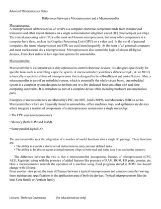
- 3. Advanced Microprocessor Notes Lecturer. ShehrevarDavierwala (for educational use only) The intel 80286 had a 24-bit address bus and was able to address up to 16 MB of RAM, compared to 1 MB for its predecessor. However cost and initial rarity of software using the memory above 1 MB meant that 80286 computers were rarely shipped with more than onemegabyte of RAM. Additionally, there was a performance penalty involved in accessing extended memory from real mode Internal architecture of 80286? Key Features - 16-bit date bus 24-bit non-multiplexed bus Packaged in a 68-pin ceramic pack 80286 has 2 24 = 16 M Byte of physical memory accessibility Fig 32.1 Basic Architecture of 80286 Memory Bank Memory of 80286 is setup as an odd bank and an even bank, just as it is for the 8086. The even bank is enabled when A 0 is low and the odd bank is enabled when is low. To access an aligned word, both A 0 will be low.
- 4. Advanced Microprocessor Notes Lecturer. ShehrevarDavierwala (for educational use only) Fig 32.2 Memory banks in 80286 Memory Addressing in 80286 1. Real Addressing Mode - It is just like as in 8086. Address is 20 bit with 16 bit segment and 16 bit offset. When 80286 is hardware reset, it automatically enters real address mode. 2. Protected Virtual Addressing Mode (PVAM) - In this we have 1 GByte of virtual memory and 16 Mbyte of physical memory. The address is 24 bit. To enter PVAM mode, Processor Status Word (PSW) is loaded by the instruction LPSW. Fig 32.3 Load Processor Status Word PE - Protection Enable MP - Monitor Processor Extension EM - Emulate Processor Extension TS - Task Switch Hardware reset is the only way to come out of protected mode. 80286 Memory Management Scheme Memory is organized into logical segments. Segment size can be anywhere between 1 Byte to 16 KByte. All 24 address pins are active and 16 MByte of physical memory is available. Descriptor It is 8-byte quantity. Each segment has a descriptor. There are two main types of descriptor - Segment Descriptor System control Descriptor Format of a Descriptor
- 5. Advanced Microprocessor Notes Lecturer. ShehrevarDavierwala (for educational use only) Fig 32.4 Descriptor Format Access Right byte definition 7 Present (P) 1 - Yes 0 - No 6-5 Descriptor Privilege level (DPL) 0 to 3 4 Segment Descriptor 1 - Segment 0 - Control For segment descriptor, i.e. for S = 1, bits 3-0 have the following meaning - 3 E 0 - Data 1 - Code 2 Expansion/ Confirming If code, Confirming: 1 means 'Yes', 0 means 'No' If data, Expand down: 1 - Yes, 0 - No (normal case) 1 R / W If code, Readable: 1 - Yes, 0 - Not If data, Writeable: 1 - Yes, 0 - Not 0 Accessed (A) A = 0, Not accessed A = 1, Accessed Descriptors are contained in a descriptor table. There are two categories of descriptor table - global and local. A system has only one global descriptor table or GDT. A local descriptor table or LDT is set up in the system for each task or closely related group of tasks. Each task can have its own descriptor table and memory area defined by the descriptors in it. Accessing Segments The 80286 microprocessor keeps the base address and limits for the descriptor tables currently in use in internal registers. These registers are load descriptor table register (LDTR) and global descriptor table register (GDTR). Descriptor in memory is addressed by adding segment selector to these registers. The descriptors contain the base address of segments, which when added with the offset in the virtual address points to the required memory location. Accessing a Segment of Higher Privilege Level Tasks operate at the lowest privilege level. Usually, segments at a lower privilege level are not allowed to access segments at a higher privilege level directly. However, a lower level segment can access a higher level segment indirectly by a Gate Descriptor. The details of a gate descriptor are given herewith.
- 6. Advanced Microprocessor Notes Lecturer. ShehrevarDavierwala (for educational use only) Fig 32.5 Privilege Level Gate Description Format Fig 32.6 Gate Descriptor Format Name Value Description Type 4 Call gate . 5 Task gate . 6 Interrupt gate . 7 Trap gate P 0 Descriptor contents are NOT valid . 1 Descriptor contents are valid DPL 0-3 Descriptor privilege level Word Count 0-31 Number of words to copy from callers stack to called procedures stack. Only used with called gates. Destination Selector 16-bit Selector Selector to target code segment (call, interrupt, task gates) Selector to target task state segment (task gate) Destination Offset 16-bit Offset Entry point within the target code segment
- 7. Advanced Microprocessor Notes Lecturer. ShehrevarDavierwala (for educational use only) Task Switching and Task gates Each task in a PVAM system has a 22-word task state segment (TSS) associated with it. A TSS holds copies of all registers and flags, the selector for the tasks' LDT, and a link to the TSS of the previously executing task. Descriptors for each task state segment are kept in the global descriptor table. A task register (TR) in the 80286 holds the selector and the task state segment descriptor for the currently executing task. The load task register (LTR) instruction can be used to initialize the task register to the task state segment for a particular task. During a task switch the task register is automatically loaded with the selector and descriptor for the new task. Method of Task Switching 1. Long jump or call instructions that contain a selector which points to the Task State segment descriptor 2. IRET 3. Selectors in a long jump or call points to a task gate 4. Interrupt occurs and the vectors point to a task gate descriptor 80286 Interrupt Handling Real addressing mode has 256 interrupts with types 0-255. Each interrupt takes 4 bytes, so we have to reserve 1KByte of memory for interrupt. In PVAM mode also we have 256 interrupts but it is not assigned a fixed memory. The interrupt descriptor table can be anywhere in the physical memory. Base address of interrupt descriptor table is stored in interrupt descriptor table register (IDTR). The particular descriptor is accessed as follows - (Interrupt Type * 8) + IDTR Descriptor