Starting system basic fundamentals & its testing methods
•Télécharger en tant que PPT, PDF•
0 j'aime•132 vues
presentation explore the basic principle of starting system and testing methods in order verify the performance of system
Signaler
Partager
Signaler
Partager

Recommandé
CRDI ENGINE
CRDI stands for common rail direct injection and directly injects fuel into engine cylinders via a single common rail connected to all fuel injectors. It was introduced to remove drawbacks of earlier fuel systems and allows even petrol engines to run with very lean fuel mixtures. The key components are a high pressure fuel pump, common rail, injectors, and engine control unit. CRDI provides benefits like 25% more power and torque, superior pickup, reduced noise and vibrations, and lower fuel consumption. While it has higher initial costs and maintenance than older systems, CRDI lowers emissions and improves engine performance.
Positive crankcase ventilation
The document discusses crankcase ventilation systems and positive crankcase ventilation (PCV). PCV was invented during World War II to allow tank engines to operate while preventing water from entering the crankcase. The PCV system reduces blow-by emissions from the engine by up to 20% of total hydrocarbons. It works by using a PCV valve and hose to siphon crankcase vapors directly into the intake manifold or throttle body.
Crdi ppt
Crdi technology is more efficient and advance technology in the field of automobile engineering. This technology is using at a large scale by a number of car companies. In this presentation you will find the basic principle, working, and component description of crdi technology.
Electronic Fuel Injection System
Electronic fuel injection systems use an electric fuel pump and pressure, rather than engine vacuum, to spray fuel into the engine intake manifold or combustion chambers. This allows for more precise fuel delivery and improved engine performance compared to carbureted systems. Modern systems are computer-controlled and use various sensors to monitor engine operating conditions and adjust fuel delivery accordingly through fuel injectors.
Ignition system
The document provides information on the ignition system for spark ignition engines. It discusses the basics of ignition systems including the need for an ignition source in SI engines. It describes the basic components and working of battery and magneto ignition systems. Transistorized ignition systems and capacitive discharge ignition systems are also summarized as more advanced ignition systems. The document discusses the vacuum advance mechanism used to optimize spark timing based on engine load. It also describes the centrifugal advance mechanism used to advance spark timing with increasing engine speed.
Study of transmission system of automobile
The document summarizes the transmission system of an automobile. It defines the transmission system as the mechanism that transmits power from the engine to the driving wheels. It has three main components - the clutch, gearbox, and propeller shaft. The transmission allows the engine to be disconnected from the wheels, connected smoothly, and drives the wheels at different speeds. It enables torque multiplication for starting and leverage variation between the engine and wheels. The document discusses different types of transmission systems including mechanical, hydraulic, electrical and automatic systems. It also explains the power flow in sliding mesh and constant mesh gearboxes.
Sliding mesh gear box
A gearbox manages a series of gear ratios to deliver power from an engine to a transmission. It provides multiple torque ratios for varying acceleration and climbing gradients, and allows for reversing the vehicle's motion. A sliding mesh gearbox typically has 3 forward gears and 1 reverse gear. It uses spur gears on the main shaft that engage with gears on the lay shaft by sliding into position. When the engine is running and clutch engaged, power flows from the clutch shaft gear to the lay shaft gears, but the main shaft remains idle until a gear is engaged to transfer power through the transmission.
MULTI-POINT FUEL INJECTION SYSTEM
Multipoint fuel injection (MPFI) systems provide better control of the air-fuel ratio compared to carburetors. MPFI systems use multiple fuel injectors, with one injector per cylinder, to inject fuel into the engine's intake ports or manifold. This allows supplying the optimum air-fuel ratio to each cylinder for all operating conditions. MPFI systems are electronically controlled using sensors to monitor various engine parameters and optimize fuel delivery and emissions performance. While more complex than carburetors, MPFI systems improve fuel efficiency, power, and reduce emissions.
Principles of carburetion
1) The document discusses the principles of carburetion, explaining how a carburetor works to provide an air-fuel mixture to engines. It mixes air and fuel through venturi suction and different metering systems that control the mixture at idle, acceleration, high speeds, and full power.
2) A carburetor uses atmospheric pressure, temperature, volatility, and atomization to control the evaporation of fuel into a vapor that can be mixed with air. Different parts of the carburetor like the float, jets, and chokes maintain the proper air-fuel ratio for starting and various engine conditions.
3) Issues like excessive fuel consumption, sluggish engine performance, poor idling,
Charging Systems - Copy.ppt
The charging system consists of a belt-driven alternator, battery, and voltage regulator. The alternator converts mechanical energy from the crankshaft into electrical current using a rotor and stator. The rotor's rotating magnetic field induces current in the stationary stator windings. Rectifiers convert this alternating current into direct current to charge the battery and power electrical components. The voltage regulator controls the rotor's magnetic field strength to maintain a constant output voltage.
Automobile engines
The document provides information about internal combustion engines, including:
1) It discusses the history and development of internal combustion engines from 1860 to the present, including key inventors and innovations.
2) It covers the classification and components of internal combustion engines, explaining features like operating cycles, cylinder configurations, valve locations, and fuels.
3) It describes the operation of 4-stroke and 2-stroke engine cycles, and includes diagrams and animations to illustrate the combustion process.
Lubrication system for an automobile
The document describes the purpose and components of an engine lubrication system. The key purposes of lubrication are to reduce friction, seal components, clean the engine, cool the engine, absorb shocks, and absorb contaminants. The main types of lubrication systems are mist/petrol-oil premix, autolube, splash, and pressure-fed wet or dry sump systems. The document outlines the components of these systems including the oil sump, pump, pickup, pressure regulator, filter, galleries, and indicators. It explains how each component functions to circulate oil through the engine.
Multipoint Fuel Injection System (MPFI)
This document discusses fuel injection systems, specifically multiport fuel injection (MPFI) and direct fuel injection (DFI) systems. It provides details on:
- The components and functioning of MPFI systems, including the air intake system, fuel delivery system, and electronic control system. It notes MPFI injects fuel into intake ports.
- The components and functioning of DFI systems, including high pressure fuel rails and injectors located in the cylinder. DFI allows for stratified charge and homogeneous operating modes.
- The advantages of DFI over MPFI, including more complete combustion, better temperature patterns during combustion, and reduced intake duct losses, leading to improved efficiency.
Components and working of carburettor
The carburetor mixes air and fuel for combustion in a petrol engine. It has several main components: the throttle valve controls the air-fuel mixture supplied to the engine; a strainer filters fuel particles; the venturi decreases air pressure to draw fuel from the float chamber, which maintains the fuel level; and the choke valve controls the air-fuel ratio for starting a cold engine.
Need of gear box
The document discusses the need for gear boxes in vehicles. It describes the various resistances that act on a moving vehicle, such as rolling resistance from friction between the tires and road, wind resistance which increases with speed, and gradient resistance from road inclines. A gear box is necessary because the engine's torque varies with speed but vehicles must be able to maintain motion over varying resistances and road conditions. By changing gears, the transmission can better match the engine's output to the demands placed on the driving wheels.
Petrol engine vs diesel engine
Diesel engines differ from petrol/gasoline engines in that diesel engines ignite fuel via compression rather than with a spark plug. Diesel engines have higher compression ratios than petrol engines, ranging from 14:1 to 25:1. This makes diesel engines more efficient but also more expensive than petrol engines. While diesel engines have advantages like better fuel efficiency and reliability, they also have disadvantages like being noisier, producing more emissions, and being harder to start in cold weather. Both engine types are commonly used in vehicles, though diesel sees more use in larger transport like trucks and buses.
Transmission systems
The document summarizes the key components and functions of a vehicle transmission system. It discusses the purpose of transmitting engine torque to drive the wheels. It then describes the main types of transmissions including manual, automatic, CVT, and their basic workings. The document also explains the purpose and function of key components that work together in a transmission system, such as the clutch, gearbox, driveshaft, differential, and universal joints.
lubrication system in ic engine
The document discusses lubrication systems in internal combustion engines. It defines lubrication as applying a substance like oil or grease to minimize friction and allow smooth movement. There are three main types of lubrication systems - mist, wet sump, and dry sump. Wet sump systems use an oil sump at the engine base and either splash or pressure pumps to circulate oil. Dry sump systems store extra oil outside the engine and use scavenging pumps to circulate it through the engine and an external heat exchanger.
Abnormal combustion in si engines ppt ic engine
The document discusses abnormal combustion in spark ignition engines. Under normal combustion, the flame travels uniformly across the combustion chamber. Abnormal combustion occurs when combustion deviates from this normal behavior. Two types of abnormal combustion are pre-ignition and knocking. Pre-ignition occurs when the fuel-air mixture ignites before the spark, while knocking is the auto-ignition of unburned fuel late in the combustion cycle. Both pre-ignition and knocking can damage engine components and reduce performance. The causes of abnormal combustion include issues with fuel quality, engine parts, air quality, cooling, vibration, and operating environment.
Lubrication system
The document discusses lubrication systems for engines. It describes the purpose of lubrication as reducing friction, protecting from wear, removing impurities, forming seals, and serving as a coolant. The main lubrication systems are mist, wet sump, and dry sump. Mist lubrication uses oil mixed with fuel for 2-stroke engines. Wet sump systems include splash and circulating pumps or pressure systems. Properties of lubricants that are important include viscosity, flash point, pour point, and additives that improve properties.
ppt of fuel injection system
The document discusses different types of injection systems used in diesel engines. It describes air injection systems which inject fuel along with compressed air but are not commonly used now. It also describes three types of solid or airless injection systems: common rail, individual pump and injector, and distributor injection. The common rail system uses a single high-pressure fuel pump to supply fuel to a header pipe that distributes to each injector. The individual pump system has a separate pump for each injector. The distributor system uses a central pump and distributor block to supply fuel to injectors.
Carburettor
This document discusses the components and operation of carburetors in gasoline engines. It begins by reviewing the different types of carburetors including updraft, horizontal draft, and downdraft configurations. It then explains the basic components and circuits of a simple carburetor including the venturi and float chamber. The document goes on to describe the circuits of a complete carburetor, including the main metering, idling, power enrichment, acceleration pump, and choke circuits. Specific carburetor designs are discussed such as the Solex, Carter, and SU carburetors. The Solex uses a bi-starter for cold starting while the Carter uses multiple jets and an accelerator pump. The SU carb
Engine, types of engine
Do you know what is engine, how many types of engines are available now. How conversion of energy takes place from chemical energy to mechanical energy or useful work. Here engine classified according to their combustion, working stroke, arrangement of piston, fuel used for combustion and on the basis of ignition system. 4-stroke petrol engine and 4-stroke diesel engine are described briefly with all 4-strokes which are completed during power conversion process. 2-stroke engine or scooter engine is also described briefly with the complete details of combustion, charge( petrol,diesel ) filling process and how all 4 stroke process(suction, combustion,power stroke, exhaust) completed in 2 stroke engine.
Automobile Steering system
The document discusses vehicle steering systems. It begins with an introduction to basic steering components and principles. It then covers various topics related to steering mechanisms, including Davis and Ackerman steering mechanisms. It also discusses steering ratio, steering lock, steering gear boxes including different types, and power steering. The document provides information on key factors for proper steering such as steerability and stability.
Starter motor drive mechanism
The document discusses different types of starter drive mechanisms used in internal combustion engines. It describes how the Bendix drive, pre-engagement drive, axial/sliding armature drive, and overrunning clutch work to engage the starter motor pinion gear with the flywheel and disengage it once the engine starts to prevent damage. The pre-engagement drive uses a solenoid to shift the pinion into mesh before motor startup. The axial drive allows the entire armature unit to move forward and engage the pinion. An overrunning clutch transfers torque only from motor to engine and freewheels in the other direction.
CI engine
The document summarizes combustion in compression ignition (CI) engines. It describes how combustion occurs simultaneously in many spots in a non-homogeneous fuel-air mixture, controlled by fuel injection timing. The four stages of CI engine combustion are ignition delay, premixed combustion, mixing-controlled combustion, and late combustion. Factors like injection timing and fuel quality can affect the ignition delay period. Knock may occur if ignition delay is too long. The document provides diagrams to illustrate CI engine combustion processes and types.
mpfi system ppt
This document discusses multi-cylinder engines and port fuel injection systems. It describes how port fuel injection helps ensure a uniform air-fuel mixture in each cylinder by injecting the same amount of gasoline into the intake manifold. It then provides details on the components and working of port multi-point fuel injection (MPFI) systems, including electronic control systems, fuel systems, air induction systems, sensors that feed information to the engine control unit, and how this helps precisely control fuel injection.
Automobile- drive systems
automobile drives systems
types of drive systems
front engine front wheel drive
front engine rear wheel drive
rear engine rear wheel drive
four wheel drive
62668724c2f9bSTARTING SYSTEM final ppt.pdf
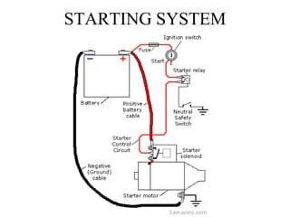
The starting system uses a battery, ignition switch, solenoid, and starter motor to provide electrical current and turn the motor's armature, engaging the starter drive and pinion gear with the flywheel ring gear to crank the engine. When the ignition key is turned on, current flows through the solenoid coil, closing the contacts and connecting the battery to the starter motor. The starter motor then turns the armature at high rpm through electromagnetic fields, and the pinion gear meshes with the flywheel gear to start the engine through a gear reduction ratio of typically 16:1 to 20:1.
Starting system .pdfhtdu,yjfvbnyhrdgcvhfd
The starting system includes components that convert electrical energy from the battery into mechanical energy to turn the engine's crankshaft. It consists of the battery, starter motor, solenoid, ignition switch, and sometimes a starter relay. When the ignition key is turned to start, the solenoid closes the high-current circuit to power the starter motor. The starter motor then spins a drive gear that engages the flywheel to crank the engine until it starts.
Contenu connexe
Tendances
Principles of carburetion
1) The document discusses the principles of carburetion, explaining how a carburetor works to provide an air-fuel mixture to engines. It mixes air and fuel through venturi suction and different metering systems that control the mixture at idle, acceleration, high speeds, and full power.
2) A carburetor uses atmospheric pressure, temperature, volatility, and atomization to control the evaporation of fuel into a vapor that can be mixed with air. Different parts of the carburetor like the float, jets, and chokes maintain the proper air-fuel ratio for starting and various engine conditions.
3) Issues like excessive fuel consumption, sluggish engine performance, poor idling,
Charging Systems - Copy.ppt
The charging system consists of a belt-driven alternator, battery, and voltage regulator. The alternator converts mechanical energy from the crankshaft into electrical current using a rotor and stator. The rotor's rotating magnetic field induces current in the stationary stator windings. Rectifiers convert this alternating current into direct current to charge the battery and power electrical components. The voltage regulator controls the rotor's magnetic field strength to maintain a constant output voltage.
Automobile engines
The document provides information about internal combustion engines, including:
1) It discusses the history and development of internal combustion engines from 1860 to the present, including key inventors and innovations.
2) It covers the classification and components of internal combustion engines, explaining features like operating cycles, cylinder configurations, valve locations, and fuels.
3) It describes the operation of 4-stroke and 2-stroke engine cycles, and includes diagrams and animations to illustrate the combustion process.
Lubrication system for an automobile
The document describes the purpose and components of an engine lubrication system. The key purposes of lubrication are to reduce friction, seal components, clean the engine, cool the engine, absorb shocks, and absorb contaminants. The main types of lubrication systems are mist/petrol-oil premix, autolube, splash, and pressure-fed wet or dry sump systems. The document outlines the components of these systems including the oil sump, pump, pickup, pressure regulator, filter, galleries, and indicators. It explains how each component functions to circulate oil through the engine.
Multipoint Fuel Injection System (MPFI)
This document discusses fuel injection systems, specifically multiport fuel injection (MPFI) and direct fuel injection (DFI) systems. It provides details on:
- The components and functioning of MPFI systems, including the air intake system, fuel delivery system, and electronic control system. It notes MPFI injects fuel into intake ports.
- The components and functioning of DFI systems, including high pressure fuel rails and injectors located in the cylinder. DFI allows for stratified charge and homogeneous operating modes.
- The advantages of DFI over MPFI, including more complete combustion, better temperature patterns during combustion, and reduced intake duct losses, leading to improved efficiency.
Components and working of carburettor
The carburetor mixes air and fuel for combustion in a petrol engine. It has several main components: the throttle valve controls the air-fuel mixture supplied to the engine; a strainer filters fuel particles; the venturi decreases air pressure to draw fuel from the float chamber, which maintains the fuel level; and the choke valve controls the air-fuel ratio for starting a cold engine.
Need of gear box
The document discusses the need for gear boxes in vehicles. It describes the various resistances that act on a moving vehicle, such as rolling resistance from friction between the tires and road, wind resistance which increases with speed, and gradient resistance from road inclines. A gear box is necessary because the engine's torque varies with speed but vehicles must be able to maintain motion over varying resistances and road conditions. By changing gears, the transmission can better match the engine's output to the demands placed on the driving wheels.
Petrol engine vs diesel engine
Diesel engines differ from petrol/gasoline engines in that diesel engines ignite fuel via compression rather than with a spark plug. Diesel engines have higher compression ratios than petrol engines, ranging from 14:1 to 25:1. This makes diesel engines more efficient but also more expensive than petrol engines. While diesel engines have advantages like better fuel efficiency and reliability, they also have disadvantages like being noisier, producing more emissions, and being harder to start in cold weather. Both engine types are commonly used in vehicles, though diesel sees more use in larger transport like trucks and buses.
Transmission systems
The document summarizes the key components and functions of a vehicle transmission system. It discusses the purpose of transmitting engine torque to drive the wheels. It then describes the main types of transmissions including manual, automatic, CVT, and their basic workings. The document also explains the purpose and function of key components that work together in a transmission system, such as the clutch, gearbox, driveshaft, differential, and universal joints.
lubrication system in ic engine
The document discusses lubrication systems in internal combustion engines. It defines lubrication as applying a substance like oil or grease to minimize friction and allow smooth movement. There are three main types of lubrication systems - mist, wet sump, and dry sump. Wet sump systems use an oil sump at the engine base and either splash or pressure pumps to circulate oil. Dry sump systems store extra oil outside the engine and use scavenging pumps to circulate it through the engine and an external heat exchanger.
Abnormal combustion in si engines ppt ic engine
The document discusses abnormal combustion in spark ignition engines. Under normal combustion, the flame travels uniformly across the combustion chamber. Abnormal combustion occurs when combustion deviates from this normal behavior. Two types of abnormal combustion are pre-ignition and knocking. Pre-ignition occurs when the fuel-air mixture ignites before the spark, while knocking is the auto-ignition of unburned fuel late in the combustion cycle. Both pre-ignition and knocking can damage engine components and reduce performance. The causes of abnormal combustion include issues with fuel quality, engine parts, air quality, cooling, vibration, and operating environment.
Lubrication system
The document discusses lubrication systems for engines. It describes the purpose of lubrication as reducing friction, protecting from wear, removing impurities, forming seals, and serving as a coolant. The main lubrication systems are mist, wet sump, and dry sump. Mist lubrication uses oil mixed with fuel for 2-stroke engines. Wet sump systems include splash and circulating pumps or pressure systems. Properties of lubricants that are important include viscosity, flash point, pour point, and additives that improve properties.
ppt of fuel injection system
The document discusses different types of injection systems used in diesel engines. It describes air injection systems which inject fuel along with compressed air but are not commonly used now. It also describes three types of solid or airless injection systems: common rail, individual pump and injector, and distributor injection. The common rail system uses a single high-pressure fuel pump to supply fuel to a header pipe that distributes to each injector. The individual pump system has a separate pump for each injector. The distributor system uses a central pump and distributor block to supply fuel to injectors.
Carburettor
This document discusses the components and operation of carburetors in gasoline engines. It begins by reviewing the different types of carburetors including updraft, horizontal draft, and downdraft configurations. It then explains the basic components and circuits of a simple carburetor including the venturi and float chamber. The document goes on to describe the circuits of a complete carburetor, including the main metering, idling, power enrichment, acceleration pump, and choke circuits. Specific carburetor designs are discussed such as the Solex, Carter, and SU carburetors. The Solex uses a bi-starter for cold starting while the Carter uses multiple jets and an accelerator pump. The SU carb
Engine, types of engine
Do you know what is engine, how many types of engines are available now. How conversion of energy takes place from chemical energy to mechanical energy or useful work. Here engine classified according to their combustion, working stroke, arrangement of piston, fuel used for combustion and on the basis of ignition system. 4-stroke petrol engine and 4-stroke diesel engine are described briefly with all 4-strokes which are completed during power conversion process. 2-stroke engine or scooter engine is also described briefly with the complete details of combustion, charge( petrol,diesel ) filling process and how all 4 stroke process(suction, combustion,power stroke, exhaust) completed in 2 stroke engine.
Automobile Steering system
The document discusses vehicle steering systems. It begins with an introduction to basic steering components and principles. It then covers various topics related to steering mechanisms, including Davis and Ackerman steering mechanisms. It also discusses steering ratio, steering lock, steering gear boxes including different types, and power steering. The document provides information on key factors for proper steering such as steerability and stability.
Starter motor drive mechanism
The document discusses different types of starter drive mechanisms used in internal combustion engines. It describes how the Bendix drive, pre-engagement drive, axial/sliding armature drive, and overrunning clutch work to engage the starter motor pinion gear with the flywheel and disengage it once the engine starts to prevent damage. The pre-engagement drive uses a solenoid to shift the pinion into mesh before motor startup. The axial drive allows the entire armature unit to move forward and engage the pinion. An overrunning clutch transfers torque only from motor to engine and freewheels in the other direction.
CI engine
The document summarizes combustion in compression ignition (CI) engines. It describes how combustion occurs simultaneously in many spots in a non-homogeneous fuel-air mixture, controlled by fuel injection timing. The four stages of CI engine combustion are ignition delay, premixed combustion, mixing-controlled combustion, and late combustion. Factors like injection timing and fuel quality can affect the ignition delay period. Knock may occur if ignition delay is too long. The document provides diagrams to illustrate CI engine combustion processes and types.
mpfi system ppt
This document discusses multi-cylinder engines and port fuel injection systems. It describes how port fuel injection helps ensure a uniform air-fuel mixture in each cylinder by injecting the same amount of gasoline into the intake manifold. It then provides details on the components and working of port multi-point fuel injection (MPFI) systems, including electronic control systems, fuel systems, air induction systems, sensors that feed information to the engine control unit, and how this helps precisely control fuel injection.
Automobile- drive systems
automobile drives systems
types of drive systems
front engine front wheel drive
front engine rear wheel drive
rear engine rear wheel drive
four wheel drive
Tendances (20)
Similaire à Starting system basic fundamentals & its testing methods
62668724c2f9bSTARTING SYSTEM final ppt.pdf
The starting system uses a battery, ignition switch, solenoid, and starter motor to provide electrical current and turn the motor's armature, engaging the starter drive and pinion gear with the flywheel ring gear to crank the engine. When the ignition key is turned on, current flows through the solenoid coil, closing the contacts and connecting the battery to the starter motor. The starter motor then turns the armature at high rpm through electromagnetic fields, and the pinion gear meshes with the flywheel gear to start the engine through a gear reduction ratio of typically 16:1 to 20:1.
Starting system .pdfhtdu,yjfvbnyhrdgcvhfd
The starting system includes components that convert electrical energy from the battery into mechanical energy to turn the engine's crankshaft. It consists of the battery, starter motor, solenoid, ignition switch, and sometimes a starter relay. When the ignition key is turned to start, the solenoid closes the high-current circuit to power the starter motor. The starter motor then spins a drive gear that engages the flywheel to crank the engine until it starts.
Chapter 40
The cranking circuit includes the starter motor, battery, starter solenoid, and ignition switch. The starter motor uses electromagnetic principles to convert electrical energy from the battery into mechanical rotation of the engine. When the ignition switch is turned on, current flows through the solenoid and starter motor to engage the drive pinion with the flywheel and rotate the engine until it starts.
Automotive starting system.
The starting system includes the battery, starter motor, solenoid, ignition switch, and neutral safety switch. The battery stores electrical energy to power the starter motor, a small electric motor that converts electrical energy into mechanical energy to spin the crankshaft. The solenoid connects the battery to the starter motor when activated. The ignition switch controls power to the starting system, while the neutral safety switch prevents starting in gear. Together, these components allow the engine to be started electrically.
Starting system overview of automotive.pptx
The starting system uses electrical energy from the battery to power the starter motor and convert it into mechanical energy to start the engine. The ignition switch distributes current to different circuits needed for starting. The neutral safety switch prevents the starter from engaging unless the transmission is in neutral or park. A starter relay allows a small current from the ignition switch to control a large current from the battery to the starter motor. The starter motor is a powerful electric motor that spins the engine via a pinion gear engaging with the flywheel. The starter solenoid acts as a relay for the starter and engages the pinion gear with the flywheel when powered.
three phase induction machine starter
This document discusses different types of starters for 3-phase induction motors, including their operation and advantages/disadvantages. It describes stator resistance, auto-transformer, star-delta, rotor resistance, and direct online starters. The star-delta starter connects the motor in a star configuration at start to reduce voltage and current by 1/3, then switches to delta for run. The direct online starter connects the motor directly to full voltage, providing maximum torque but also maximum starting current of 6-8 times full load current. Variable frequency drives control motor speed by varying supply frequency and voltage.
Starting
The document provides an overview of typical starting systems used in Toyota vehicles. It describes the components that make up automatic and manual transmission starting systems, including the starter motor, magnetic switch, over-running clutch, ignition switch contacts, park/neutral or clutch start switches. It explains how gear reduction and planetary reduction segment starter motors work to engage the flywheel ring gear and start the engine. Common diagnosis steps are outlined, such as visual inspection, current draw testing, and voltage drop testing to identify electrical or mechanical issues preventing the engine from cranking.
Vk
This document provides an overview of control circuits and components for electrical machines, including DC motors and AC motors. It discusses various switch types, relays, timers, and interlocking circuits used in motor controls. For DC motors, it describes series relay starters, time acceleration starters, field failure protection, and plugging control. For AC motors, it covers DOL starters, star-delta starters, automatic transformer starters, reversing motor direction, and dynamic braking. The document is intended to explain the basic control circuits and components used for operating electrical machines.
CONTROL OF ELECTRICAL MACHINES
This document provides an overview of control circuits and components for electrical machines, including DC motors and AC motors. It discusses various switch types, relays, timers, and interlocking circuits used in motor controls. For DC motors, it describes series relay starters, time acceleration starters, field failure protection, and plugging control. For AC motors, it covers DOL starters, star-delta starters, automatic transformer starters, reversing motor direction, and dynamic braking. The document is a technical report submitted by K. Venkatachalam on the topic of controlling electrical machines.
starting system.pdf
The starting system uses a starter motor to engage the engine's flywheel ring gear via a pinion gear, driving the engine at about 200 RPM until it starts. The typical starting system includes a starter motor, magnetic switch, over-running clutch, ignition switch contacts, and park/neutral or clutch start switches. Diagnosis of starting issues involves visual inspections, current draw tests, voltage drop tests, and operational tests to identify electrical or mechanical faults like a dead battery, melted fuse, or loose connections.
motor_1684283145.pdf
The document discusses various control devices and starting methods for industrial motors. It describes disconnecting switches, manual circuit breakers, cam switches, pushbuttons, control relays, thermal relays, magnetic contactors, and proximity detectors that can be used for motor control. Starting methods covered include direct online, stator resistance, autotransformer, star-delta, and rotor resistance starting. Soft starting and reversing motor direction are also summarized. Diagrams are used to illustrate control systems and motor connections.
ignition system.ppt
The ignition system provides spark to ignite the air-fuel mixture in spark-ignition engines. It uses an ignition coil to generate high voltage sparks for the spark plugs, which are timed to fire as the pistons near top dead center on the compression stroke. Sensors detect engine speed and load to vary ignition timing for optimal performance and efficiency. The distributor routes high voltage ignition to each cylinder in the correct firing order.
Electromagnetic Clutch
If you want to know information about electromagnetic clutch manufacturers then web portal of tradeindia provide the best listing of manufacturers,suppliers and Exporters of electromagnetic clutch.
TYPES OF ELECTRICAL STARTERS
This ppt is for your education purpose.
I can explain the electrical starters in very best ways ,
you can understande the all electrical starters in very easy methods.
For your any inquiry,
CONTECT NO : - 9082557285
CREATED BY : - AYUSH .A. PITHAL
Ignition system
The ignition system provides a spark to ignite the air-fuel mixture in spark ignition engines. It generates high voltage sparks through an ignition coil to create arcs at the spark plug electrodes. The system times the sparks so they occur when the pistons are near top dead center on the compression stroke. It can vary ignition timing based on engine speed, load, and other operating conditions to optimize combustion.
Unit I Introduction to Solid State Drives.pptx
The document discusses electric drives and their characteristics. It describes the key parts of electric drives including the power modulator, control unit, and sensing unit. The power modulator regulates power from the source to the motor. The control unit controls the power modulator and protects the system. The sensing unit measures parameters like motor current and speed. Electric drives offer advantages like wide operating ranges and flexible control but have higher initial costs than other drive types. Load torques on electric drives include friction, windage, and torque for useful work. Drives can operate in different modes including constant torque, constant power, and all four quadrants of the speed-torque plane. Both steady state and transient stability are important considerations.
BATTERY OPERATED IGNITION SYSTEM
This document summarizes the key components of an ignition system used in petrol cars, including a spark plug, ignition coil, distributor, and distributor cap. It explains that the ignition coil transforms the low voltage from the battery to the high voltage needed for the spark plug to ignite the fuel mixture. The distributor then routes this high voltage to the correct spark plug at the proper time. Ignition timing, or when the spark plug fires in relation to the piston position, is also discussed, noting that it can be advanced or retarded based on engine speed and load. Vacuum advance is mentioned as one method to control ignition timing.
Torque converter
A torque converter is a fluid coupling used in automatic transmissions that transfers power from the engine to the transmission. It contains an impeller connected to the engine, a turbine connected to the transmission, and a stator in between. In different operating modes like stall and acceleration, the torque converter can multiply torque to help vehicles start moving or can act like a fluid coupling at higher speeds. Problems that can occur include overheating, stator clutch issues, blade damage, and housing distortion from extreme operating conditions.
Transmission system
The document provides an overview of automotive transmission systems, including their main components and functions. It discusses the purpose of the transmission to transmit power from the engine to the driving wheels through a system of gears that allows for different speed and torque ratios. The key components covered are the clutch, gearbox, driveshaft, differential, and axle. Manual, automated manual, automatic, continuously variable, and dual-clutch transmissions are also summarized.
Similaire à Starting system basic fundamentals & its testing methods (20)
Dernier
Charging Fueling & Infrastructure (CFI) Program Resources by Cat Plein
Cat Plein, Development & Communications Director of Forth, gave this presentation at the Forth and Electrification Coalition CFI Grant Program - Overview and Technical Assistance webinar on June 12, 2024.
Charging and Fueling Infrastructure Grant: Round 2 by Brandt Hertenstein
Brandt Hertenstein, Program Manager of the Electrification Coalition gave this presentation at the Forth and Electrification Coalition CFI Grant Program - Overview and Technical Assistance webinar on June 12, 2024.
一比一原版(WashU文凭证书)圣路易斯华盛顿大学毕业证如何办理
一模一样【微信:176555708】【(WashU文凭证书)圣路易斯华盛顿大学毕业证成绩单Offer】【微信:176555708】(留信学历认证永久存档查询)采用学校原版纸张、特殊工艺完全按照原版一比一制作(包括:隐形水印,阴影底纹,钢印LOGO烫金烫银,LOGO烫金烫银复合重叠,文字图案浮雕,激光镭射,紫外荧光,温感,复印防伪)行业标杆!精益求精,诚心合作,真诚制作!多年品质 ,按需精细制作,24小时接单,全套进口原装设备,十五年致力于帮助留学生解决难题,业务范围有加拿大、英国、澳洲、韩国、美国、新加坡,新西兰等学历材料,包您满意。
【业务选择办理准则】
一、工作未确定,回国需先给父母、亲戚朋友看下文凭的情况,办理一份就读学校的毕业证【微信:176555708】文凭即可
二、回国进私企、外企、自己做生意的情况,这些单位是不查询毕业证真伪的,而且国内没有渠道去查询国外文凭的真假,也不需要提供真实教育部认证。鉴于此,办理一份毕业证【微信:176555708】即可
三、进国企,银行,事业单位,考公务员等等,这些单位是必需要提供真实教育部认证的,办理教育部认证所需资料众多且烦琐,所有材料您都必须提供原件,我们凭借丰富的经验,快捷的绿色通道帮您快速整合材料,让您少走弯路。
留信网认证的作用:
1:该专业认证可证明留学生真实身份
2:同时对留学生所学专业登记给予评定
3:国家专业人才认证中心颁发入库证书
4:这个认证书并且可以归档倒地方
5:凡事获得留信网入网的信息将会逐步更新到个人身份内,将在公安局网内查询个人身份证信息后,同步读取人才网入库信息
6:个人职称评审加20分
7:个人信誉贷款加10分
8:在国家人才网主办的国家网络招聘大会中纳入资料,供国家高端企业选择人才
→ 【关于价格问题(保证一手价格)
我们所定的价格是非常合理的,而且我们现在做得单子大多数都是代理和回头客户介绍的所以一般现在有新的单子 我给客户的都是第一手的代理价格,因为我想坦诚对待大家 不想跟大家在价格方面浪费时间
对于老客户或者被老客户介绍过来的朋友,我们都会适当给一些优惠。
选择实体注册公司办理,更放心,更安全!我们的承诺:可来公司面谈,可签订合同,会陪同客户一起到教育部认证窗口递交认证材料,客户在教育部官方认证查询网站查询到认证通过结果后付款,不成功不收费!
EV Charging at MFH Properties by Whitaker Jamieson
Whitaker Jamieson, Senior Specialist at Forth, gave this presentation at the Forth Addressing The Challenges of Charging at Multi-Family Housing webinar on June 11, 2024.
Here's Why Every Semi-Truck Should Have ELDs
Implementing ELDs or Electronic Logging Devices is slowly but surely becoming the norm in fleet management. Why? Well, integrating ELDs and associated connected vehicle solutions like fleet tracking devices lets businesses and their in-house fleet managers reap several benefits. Check out the post below to learn more.
一比一原版(UMich毕业证)密歇根大学|安娜堡分校毕业证如何办理
UMich毕业证成绩单【微信95270640】(密歇根大学|安娜堡分校毕业证成绩单本科学历)Q微信95270640(补办UMich学位文凭证书)密歇根大学|安娜堡分校留信网学历认证怎么办理密歇根大学|安娜堡分校毕业证成绩单精仿本科学位证书硕士文凭证书认证Seneca College diplomaoffer,Transcript办理硕士学位证书造假密歇根大学|安娜堡分校假文凭学位证书制作UMich本科毕业证书硕士学位证书精仿密歇根大学|安娜堡分校学历认证成绩单修改制作,办理真实认证、留信认证、使馆公证、购买成绩单,购买假文凭,购买假学位证,制造假国外大学文凭、毕业公证、毕业证明书、录取通知书、Offer、在读证明、雅思托福成绩单、假文凭、假毕业证、请假条、国际驾照、网上存档可查!
文凭办理流程:
1客户提供办理信息:姓名生日专业学位毕业时间等(如信息不确定可以咨询顾问:微信95270640我们有专业老师帮你查询);
2开始安排制作毕业证成绩单电子图;
3毕业证成绩单电子版做好以后发送给您确认;
4毕业证成绩单电子版您确认信息无误之后安排制作成品;
5成品做好拍照或者视频给您确认;
6快递给客户(国内顺丰国外DHLUPS等快读邮寄)。
7完成交易删除客户资料
高精端提供以下服务:
一:密歇根大学|安娜堡分校密歇根大学|安娜堡分校毕业证假文凭全套材料从防伪到印刷水印底纹到钢印烫金
二:真实使馆认证(留学人员回国证明)使馆存档
三:真实教育部认证教育部存档教育部留服网站可查
四:留信认证留学生信息网站可查
五:与学校颁发的相关证件1:1纸质尺寸制定(定期向各大院校毕业生购买最新版本毕,业证成绩单保证您拿到的是鲁昂大学内部最新版本毕业证成绩单微信95270640)
A.为什么留学生需要操作留信认证?
留信认证全称全国留学生信息服务网认证,隶属于北京中科院。①留信认证门槛条件更低,费用更美丽,并且包过,完单周期短,效率高②留信认证虽然不能去国企,但是一般的公司都没有问题,因为国内很多公司连基本的留学生学历认证都不了解。这对于留学生来说,这就比自己光拿一个证书更有说服力,因为留学学历可以在留信网站上进行查询!
B.为什么我们提供的毕业证成绩单具有使用价值?
查询留服认证是国内鉴别留学生海外学历的唯一途径但认证只是个体行为不是所有留学生都操作所以没有办理认证的留学生的学历在国内也是查询不到的他们也仅仅只有一张文凭。所以这时候我们提供的和学校颁发的一模一样的毕业证成绩单就有了使用价值。他们熟识起来还成了无话不谈的好朋友可惜快乐的时光总是太短太匆忙有一次当他们在楼下捉迷藏时一根长竹竿居然穿越安全网从高空砸下不偏不倚重重地砸在小伙伴阿新稚嫩的肩上父亲再也不让山娃上工地玩了有一天因为过于思念小伙伴山娃还偷偷地跑到工地上去找去唤无奈小伙伴们全不知去向当山娃折好只纸鹤让父亲转交阿新时父亲哽咽了摆摆手说阿新早回老家疗伤去了当山娃追问缘何不留在城里疗伤时父亲沉默了好久才幽幽地说城里开支大没不
Expanding Access to Affordable At-Home EV Charging by Vanessa Warheit
Vanessa Warheit, Co-Founder of EV Charging for All, gave this presentation at the Forth Addressing The Challenges of Charging at Multi-Family Housing webinar on June 11, 2024.
Dahua Security Camera System Guide esetia
Dahua provides a comprehensive guide on how to install their security camera systems. Learn about the different types of cameras and system components, as well as the installation process.
快速办理(napier毕业证书)英国龙比亚大学毕业证在读证明一模一样
学校原件一模一样【微信:741003700 】《(napier毕业证书)英国龙比亚大学毕业证》【微信:741003700 】学位证,留信认证(真实可查,永久存档)原件一模一样纸张工艺/offer、雅思、外壳等材料/诚信可靠,可直接看成品样本,帮您解决无法毕业带来的各种难题!外壳,原版制作,诚信可靠,可直接看成品样本。行业标杆!精益求精,诚心合作,真诚制作!多年品质 ,按需精细制作,24小时接单,全套进口原装设备。十五年致力于帮助留学生解决难题,包您满意。
本公司拥有海外各大学样板无数,能完美还原。
1:1完美还原海外各大学毕业材料上的工艺:水印,阴影底纹,钢印LOGO烫金烫银,LOGO烫金烫银复合重叠。文字图案浮雕、激光镭射、紫外荧光、温感、复印防伪等防伪工艺。材料咨询办理、认证咨询办理请加学历顾问Q/微741003700
【主营项目】
一.毕业证【q微741003700】成绩单、使馆认证、教育部认证、雅思托福成绩单、学生卡等!
二.真实使馆公证(即留学回国人员证明,不成功不收费)
三.真实教育部学历学位认证(教育部存档!教育部留服网站永久可查)
四.办理各国各大学文凭(一对一专业服务,可全程监控跟踪进度)
如果您处于以下几种情况:
◇在校期间,因各种原因未能顺利毕业……拿不到官方毕业证【q/微741003700】
◇面对父母的压力,希望尽快拿到;
◇不清楚认证流程以及材料该如何准备;
◇回国时间很长,忘记办理;
◇回国马上就要找工作,办给用人单位看;
◇企事业单位必须要求办理的
◇需要报考公务员、购买免税车、落转户口
◇申请留学生创业基金
留信网认证的作用:
1:该专业认证可证明留学生真实身份
2:同时对留学生所学专业登记给予评定
3:国家专业人才认证中心颁发入库证书
4:这个认证书并且可以归档倒地方
5:凡事获得留信网入网的信息将会逐步更新到个人身份内,将在公安局网内查询个人身份证信息后,同步读取人才网入库信息
6:个人职称评审加20分
7:个人信誉贷款加10分
8:在国家人才网主办的国家网络招聘大会中纳入资料,供国家高端企业选择人才
Charging Fueling & Infrastructure (CFI) Program by Kevin Miller
Kevin Miller, Senior Advisor, Business Models of the Joint Office of Energy and Transportation gave this presentation at the Forth and Electrification Coalition CFI Grant Program - Overview and Technical Assistance webinar on June 12, 2024.
按照学校原版(UniSA文凭证书)南澳大学毕业证快速办理
咨询办理【(UniSA毕业证书)南澳大学毕业证】【176555708微信号】未毕业成绩单、外壳、offer、留信学历认证(永久存档真实可查)采用学校原版纸张、特殊工艺完全按照原版一比一制作(包括:隐形水印,阴影底纹,钢印LOGO烫金烫银,LOGO烫金烫银复合重叠,文字图案浮雕,激光镭射,紫外荧光,温感,复印防伪)行业标杆!精益求精,诚心合作,真诚制作!多年品质 ,按需精细制作,24小时接单,全套进口原装设备,十五年致力于帮助留学生解决难题,业务范围有加拿大、英国、澳洲、韩国、美国、新加坡,新西兰等学历材料,包您满意。
【我们承诺采用的是学校原版纸张(纸质、底色、纹路),我们拥有全套进口原装设备,特殊工艺都是采用不同机器制作,仿真度基本可以达到100%,所有工艺效果都可提前给客户展示,不满意可以根据客户要求进行调整,直到满意为止!】
【业务选择办理准则】
一、工作未确定,回国需先给父母、亲戚朋友看下文凭的情况,办理一份就读学校的毕业证【微信176555708】文凭即可
二、回国进私企、外企、自己做生意的情况,这些单位是不查询毕业证真伪的,而且国内没有渠道去查询国外文凭的真假,也不需要提供真实教育部认证。鉴于此,办理一份毕业证【微信176555708】即可
三、进国企,银行,事业单位,考公务员等等,这些单位是必需要提供真实教育部认证的,办理教育部认证所需资料众多且烦琐,所有材料您都必须提供原件,我们凭借丰富的经验,快捷的绿色通道帮您快速整合材料,让您少走弯路。
留信网认证的作用:
1:该专业认证可证明留学生真实身份
2:同时对留学生所学专业登记给予评定
3:国家专业人才认证中心颁发入库证书
4:这个认证书并且可以归档倒地方
5:凡事获得留信网入网的信息将会逐步更新到个人身份内,将在公安局网内查询个人身份证信息后,同步读取人才网入库信息
6:个人职称评审加20分
7:个人信誉贷款加10分
8:在国家人才网主办的国家网络招聘大会中纳入资料,供国家高端企业选择人才
留信网服务项目:
1、留学生专业人才库服务(留信分析)
2、国(境)学习人员提供就业推荐信服务
3、留学人员区块链存储服务
→ 【关于价格问题(保证一手价格)】
我们所定的价格是非常合理的,而且我们现在做得单子大多数都是代理和回头客户介绍的所以一般现在有新的单子 我给客户的都是第一手的代理价格,因为我想坦诚对待大家 不想跟大家在价格方面浪费时间
对于老客户或者被老客户介绍过来的朋友,我们都会适当给一些优惠。
选择实体注册公司办理,更放心,更安全!我们的承诺:客户在留信官方认证查询网站查询到认证通过结果后付款,不成功不收费!
原版制作(澳洲WSU毕业证书)西悉尼大学毕业证文凭证书一模一样
学校原件一模一样【微信:741003700 】《(澳洲WSU毕业证书)西悉尼大学毕业证文凭证书》【微信:741003700 】学位证,留信认证(真实可查,永久存档)原件一模一样纸张工艺/offer、雅思、外壳等材料/诚信可靠,可直接看成品样本,帮您解决无法毕业带来的各种难题!外壳,原版制作,诚信可靠,可直接看成品样本。行业标杆!精益求精,诚心合作,真诚制作!多年品质 ,按需精细制作,24小时接单,全套进口原装设备。十五年致力于帮助留学生解决难题,包您满意。
本公司拥有海外各大学样板无数,能完美还原。
1:1完美还原海外各大学毕业材料上的工艺:水印,阴影底纹,钢印LOGO烫金烫银,LOGO烫金烫银复合重叠。文字图案浮雕、激光镭射、紫外荧光、温感、复印防伪等防伪工艺。材料咨询办理、认证咨询办理请加学历顾问Q/微741003700
【主营项目】
一.毕业证【q微741003700】成绩单、使馆认证、教育部认证、雅思托福成绩单、学生卡等!
二.真实使馆公证(即留学回国人员证明,不成功不收费)
三.真实教育部学历学位认证(教育部存档!教育部留服网站永久可查)
四.办理各国各大学文凭(一对一专业服务,可全程监控跟踪进度)
如果您处于以下几种情况:
◇在校期间,因各种原因未能顺利毕业……拿不到官方毕业证【q/微741003700】
◇面对父母的压力,希望尽快拿到;
◇不清楚认证流程以及材料该如何准备;
◇回国时间很长,忘记办理;
◇回国马上就要找工作,办给用人单位看;
◇企事业单位必须要求办理的
◇需要报考公务员、购买免税车、落转户口
◇申请留学生创业基金
留信网认证的作用:
1:该专业认证可证明留学生真实身份
2:同时对留学生所学专业登记给予评定
3:国家专业人才认证中心颁发入库证书
4:这个认证书并且可以归档倒地方
5:凡事获得留信网入网的信息将会逐步更新到个人身份内,将在公安局网内查询个人身份证信息后,同步读取人才网入库信息
6:个人职称评审加20分
7:个人信誉贷款加10分
8:在国家人才网主办的国家网络招聘大会中纳入资料,供国家高端企业选择人才
AadiShakti Projects ( Asp Cranes ) Raipur
Welcome to ASP Cranes, your trusted partner for crane solutions in Raipur, Chhattisgarh! With years of experience and a commitment to excellence, we offer a comprehensive range of crane services tailored to meet your lifting and material handling needs.
At ASP Cranes, we understand the importance of reliable and efficient crane operations in various industries, from construction and manufacturing to logistics and infrastructure development. That's why we strive to deliver top-notch solutions that enhance productivity, safety, and cost-effectiveness for our clients.
Our services include:
Crane Rental: Whether you need a crawler crane for heavy lifting or a hydraulic crane for versatile operations, we have a diverse fleet of well-maintained cranes available for rent. Our rental options are flexible and can be customized to suit your project requirements.
Crane Sales: Looking to invest in a crane for your business? We offer a wide selection of new and used cranes from leading manufacturers, ensuring you find the perfect equipment to match your needs and budget.
Crane Maintenance and Repair: To ensure optimal performance and safety, regular maintenance and timely repairs are essential for cranes. Our team of skilled technicians provides comprehensive maintenance and repair services to keep your equipment running smoothly and minimize downtime.
Crane Operator Training: Proper training is crucial for safe and efficient crane operation. We offer specialized training programs conducted by certified instructors to equip operators with the skills and knowledge they need to handle cranes effectively.
Custom Solutions: We understand that every project is unique, which is why we offer custom crane solutions tailored to your specific requirements. Whether you need modifications, attachments, or specialized equipment, we can design and implement solutions that meet your needs.
At ASP Cranes, customer satisfaction is our top priority. We are dedicated to delivering reliable, cost-effective, and innovative crane solutions that exceed expectations. Contact us today to learn more about our services and how we can support your project in Raipur, Chhattisgarh, and beyond. Let ASP Cranes be your trusted partner for all your crane needs!
EV Charging at Multifamily Properties by Kevin Donnelly
Kevin Donnelly gave this presentation at the Forth Addressing The Challenges of Charging at Multi-Family Housing webinar on June 11, 2024.
Catalytic Converter theft prevention - NYC.pptx
Understanding Catalytic Converter Theft:
What is a Catalytic Converter?: Learn about the function of catalytic converters in vehicles and why they are targeted by thieves.
Why are They Stolen?: Discover the valuable metals inside catalytic converters (such as platinum, palladium, and rhodium) that make them attractive to criminals.
Steps to Prevent Catalytic Converter Theft:
Parking Strategies: Tips on where and how to park your vehicle to reduce the risk of theft, such as parking in well-lit areas or secure garages.
Protective Devices: Overview of various anti-theft devices available, including catalytic converter locks, shields, and alarms.
Etching and Marking: The benefits of etching your vehicle’s VIN on the catalytic converter or using a catalytic converter marking kit to make it traceable and less appealing to thieves.
Surveillance and Monitoring: Recommendations for using security cameras and motion-sensor lights to deter thieves.
Statistics and Insights:
Theft Rates by Borough: Analysis of data to determine which borough in NYC experiences the highest rate of catalytic converter thefts.
Recent Trends: Current trends and patterns in catalytic converter thefts to help you stay aware of emerging hotspots and tactics used by thieves.
Benefits of This Presentation:
Awareness: Increase your awareness about catalytic converter theft and its impact on vehicle owners.
Practical Tips: Gain actionable insights and tips to effectively prevent catalytic converter theft.
Local Insights: Understand the specific risks in different NYC boroughs, helping you take targeted preventive measures.
This presentation aims to equip you with the knowledge and tools needed to protect your vehicle from catalytic converter theft, ensuring you are prepared and proactive in safeguarding your property.
原版制作(Exeter毕业证书)埃克塞特大学毕业证完成信一模一样
学校原件一模一样【微信:741003700 】《(Exeter毕业证书)埃克塞特大学毕业证》【微信:741003700 】学位证,留信认证(真实可查,永久存档)原件一模一样纸张工艺/offer、雅思、外壳等材料/诚信可靠,可直接看成品样本,帮您解决无法毕业带来的各种难题!外壳,原版制作,诚信可靠,可直接看成品样本。行业标杆!精益求精,诚心合作,真诚制作!多年品质 ,按需精细制作,24小时接单,全套进口原装设备。十五年致力于帮助留学生解决难题,包您满意。
本公司拥有海外各大学样板无数,能完美还原。
1:1完美还原海外各大学毕业材料上的工艺:水印,阴影底纹,钢印LOGO烫金烫银,LOGO烫金烫银复合重叠。文字图案浮雕、激光镭射、紫外荧光、温感、复印防伪等防伪工艺。材料咨询办理、认证咨询办理请加学历顾问Q/微741003700
【主营项目】
一.毕业证【q微741003700】成绩单、使馆认证、教育部认证、雅思托福成绩单、学生卡等!
二.真实使馆公证(即留学回国人员证明,不成功不收费)
三.真实教育部学历学位认证(教育部存档!教育部留服网站永久可查)
四.办理各国各大学文凭(一对一专业服务,可全程监控跟踪进度)
如果您处于以下几种情况:
◇在校期间,因各种原因未能顺利毕业……拿不到官方毕业证【q/微741003700】
◇面对父母的压力,希望尽快拿到;
◇不清楚认证流程以及材料该如何准备;
◇回国时间很长,忘记办理;
◇回国马上就要找工作,办给用人单位看;
◇企事业单位必须要求办理的
◇需要报考公务员、购买免税车、落转户口
◇申请留学生创业基金
留信网认证的作用:
1:该专业认证可证明留学生真实身份
2:同时对留学生所学专业登记给予评定
3:国家专业人才认证中心颁发入库证书
4:这个认证书并且可以归档倒地方
5:凡事获得留信网入网的信息将会逐步更新到个人身份内,将在公安局网内查询个人身份证信息后,同步读取人才网入库信息
6:个人职称评审加20分
7:个人信誉贷款加10分
8:在国家人才网主办的国家网络招聘大会中纳入资料,供国家高端企业选择人才
一比一原版(Columbia文凭证书)哥伦比亚大学毕业证如何办理
一模一样【微信:176555708】【(Columbia文凭证书)哥伦比亚大学毕业证成绩单Offer】【微信:176555708】(留信学历认证永久存档查询)采用学校原版纸张、特殊工艺完全按照原版一比一制作(包括:隐形水印,阴影底纹,钢印LOGO烫金烫银,LOGO烫金烫银复合重叠,文字图案浮雕,激光镭射,紫外荧光,温感,复印防伪)行业标杆!精益求精,诚心合作,真诚制作!多年品质 ,按需精细制作,24小时接单,全套进口原装设备,十五年致力于帮助留学生解决难题,业务范围有加拿大、英国、澳洲、韩国、美国、新加坡,新西兰等学历材料,包您满意。
【业务选择办理准则】
一、工作未确定,回国需先给父母、亲戚朋友看下文凭的情况,办理一份就读学校的毕业证【微信:176555708】文凭即可
二、回国进私企、外企、自己做生意的情况,这些单位是不查询毕业证真伪的,而且国内没有渠道去查询国外文凭的真假,也不需要提供真实教育部认证。鉴于此,办理一份毕业证【微信:176555708】即可
三、进国企,银行,事业单位,考公务员等等,这些单位是必需要提供真实教育部认证的,办理教育部认证所需资料众多且烦琐,所有材料您都必须提供原件,我们凭借丰富的经验,快捷的绿色通道帮您快速整合材料,让您少走弯路。
留信网认证的作用:
1:该专业认证可证明留学生真实身份
2:同时对留学生所学专业登记给予评定
3:国家专业人才认证中心颁发入库证书
4:这个认证书并且可以归档倒地方
5:凡事获得留信网入网的信息将会逐步更新到个人身份内,将在公安局网内查询个人身份证信息后,同步读取人才网入库信息
6:个人职称评审加20分
7:个人信誉贷款加10分
8:在国家人才网主办的国家网络招聘大会中纳入资料,供国家高端企业选择人才
→ 【关于价格问题(保证一手价格)
我们所定的价格是非常合理的,而且我们现在做得单子大多数都是代理和回头客户介绍的所以一般现在有新的单子 我给客户的都是第一手的代理价格,因为我想坦诚对待大家 不想跟大家在价格方面浪费时间
对于老客户或者被老客户介绍过来的朋友,我们都会适当给一些优惠。
选择实体注册公司办理,更放心,更安全!我们的承诺:可来公司面谈,可签订合同,会陪同客户一起到教育部认证窗口递交认证材料,客户在教育部官方认证查询网站查询到认证通过结果后付款,不成功不收费!
Dernier (19)
Charging Fueling & Infrastructure (CFI) Program Resources by Cat Plein
Charging Fueling & Infrastructure (CFI) Program Resources by Cat Plein
Charging and Fueling Infrastructure Grant: Round 2 by Brandt Hertenstein
Charging and Fueling Infrastructure Grant: Round 2 by Brandt Hertenstein
EV Charging at MFH Properties by Whitaker Jamieson
EV Charging at MFH Properties by Whitaker Jamieson
Expanding Access to Affordable At-Home EV Charging by Vanessa Warheit
Expanding Access to Affordable At-Home EV Charging by Vanessa Warheit
Charging Fueling & Infrastructure (CFI) Program by Kevin Miller
Charging Fueling & Infrastructure (CFI) Program by Kevin Miller
53286592-Global-Entrepreneurship-and-the-Successful-Growth-Strategies-of-Earl...
53286592-Global-Entrepreneurship-and-the-Successful-Growth-Strategies-of-Earl...
EV Charging at Multifamily Properties by Kevin Donnelly
EV Charging at Multifamily Properties by Kevin Donnelly
Starting system basic fundamentals & its testing methods
- 3. STARTING SYSTEM Battery provides the current to turn the starter motor. Fuse protects the circuit. Ignition switch closes the circuit. Relay uses small amount of current to control large amount. Neutral safety switch opens the circuit until the vehicle is in neutral (manual transmission), or park (Automatic). (Can be adjusted) Solenoid does the same thing as relay, but performs mechanical operation. It is an electromagnetic switch. Starter motor engages pinion gear to ring gear (mounted on flywheel, Or torque converter).
- 4. STARTING SYSTEM •Starting system uses battery power and an electric DC motor to turn engine crankshaft for engine starting. •Changes electrical energy to mechanical. •Provides gear reduction/torque multiplication (16:1 to 20:1). •When the ignition key is turned on the current flows through the solenoid coil. This closes the contacts, connecting battery to the starter motor.
- 5. STARTING SYSTEM Inside the starter motor. 1. Starter solenoid 2. Starter drive/bendix 3. Starter armature 4. Starter brushes 5. Starter bearings
- 6. STARTING SYSTEM COMMUTATOR sliding electrical connection between the motor windings and the brushes. •Insulated from each other. •Several loops of wire and a commutator with many segments are used to increase motor power and smoothness.
- 7. STARTING SYSTEM BRUSHES ride on top of the commutator to carry battery current to spinning windings. •Replaced during starter rebuilding.
- 8. STARTING SYSTEM Starter Armature consists of the armature shaft, armature core, commutator and armature windings. •Armature must produce high torque and high speeds.
- 9. STARTING SYSTEM Field winding is a stationary insulated wire wrapped in a circular shape. It creates a strong magnetic field around the motor armature.
- 10. STARTING SYSTEM Pinion Gear is attached to the starter drive and when starting the vehicle the pinion gear engages with flywheel or ring gear. It is moved by the YOKE.
- 11. STARTING SYSTEM Overrunning Clutch Starter •Locks it in one direction and unlocks it in another. •It allows the pinion gear to run free when engine begins to run.
- 12. STARTING SYSTEM Gear Reduction Starter •Has an extra gear on the armature to further increase the rotating force •Gear ratio between flywheel and armature is 45:1 •Hence, the armature turns 45 times to turn the flywheel (engine) once. •This provides high cranking torque for starting.
- 13. STARTING SYSTEM DC electric motors have three common types of internal connections: Series-wound motors develop maximum torque at initial start-up. Torque decreases as motor speed increases. Shunt-wound motors have less starting torque but more constant torque at varying speeds. Compound-wound motors have both series and shunt windings. They have good starting power with fairly consistent operating speeds.
- 14. STARTING SYSTEM Starting Solenoid •Is a high current relay (controlled by low current) •Works as an electromagnet switch •If faulty it will simply make a clicking sound when one is attempting to start the vehicle.
- 15. STARTING SYSTEM Neutral safety switch prevents the vehicle from starting while in gear. (can be adjusted) Clutch Safety Switch prevents the vehicle from starting, unless the clutch pedal is pressed. (adjustable)
- 16. STARTING SYSTEM When replacing a starter motor, make sure the spacer shims are of correct thickness are installed. •Shims sit in between the starter housing and the engine block. If these shims are left out, the pinion gear may not mesh with the flywheel gear properly, and might cause damage to the ring-gear. •Starter metallic grinding sound.
- 17. STARTING SYSTEM QUICK TESTING No crank with no headlights •Dead Battery(corroded terminals) or an open in electrical circuit. •Burned fuse. •Burned or broken wire.
- 18. STARTING SYSTEM QUICK TESTING Head lights go out when cranking •Battery may be weak. •Indicates heavy current draw. •Starter motor may be shorted.
- 19. STARTING SYSTEM QUICK TESTING Lights stay bright but, no crank •High resistance or an open in starting circuit. •Possibly Ignition switch •Wiring , solenoid, cable connections, relay, fuse.
- 20. STARTING SYSTEM Current Draw Test most of the starters draw over 200 Amps. •Hookup the VAT •Disconnect Fuel/ignition •Crank engine for 5-10 seconds and note the voltage. •Load the battery until same voltage is obtained and record the Amp. •The Amps will equal the current drawn by the starting motor. 4 Cylinder – 150/200 amps 6 Cylinder – 175/250 amps 8 Cylinder – 225/300 amps
- 21. STARTING SYSTEM Voltage Drop Test checks for high resistance across a cable/connection •Disable ignition/fuel •Hook voltmeter between +ve battery post and +ve starter terminal •Hook voltmeter between -ve battery post and starter ground. •Crank the engine (5-10Sec.), Voltmeter should not read more then 1volts. If greater: •Loose electrical connections. •Burned or pitted solenoid contacts.