SlideShare une entreprise Scribd logo
1  sur  4
Télécharger pour lire hors ligne
ERRS2 Control system
24VDCEmergency power supply from ship
16 - 36 VDC Max. 0.5A
Term. D1 to +24VDC
Term. E1 to 0VDC
ERU1
ERU4
ERU3
ERU2
ERU5
ERU6
ERU7
ERU8
ERU9
ERU10
INPUT 1
INPUT 2
INPUT 3
INPUT 4
Alarm relay output. Normally closed contact
Max.24VDC 1,0A
Relay output 1, COM-NO-NC
Max. 24VDC 1,0A
Relay output 2, COM-NO-NC
Max. 24VDC 1,0A
Connection box
See sheet 2, 3 and 4 for further details!
H20 ERU release unit
No machining is allowed on the enclosure!
IMPORTANT!
Ground Connection Device
For ground connection of cable screen and
the ERRS2 control system see specifications
on sheet 4
Inputs can be of the following types:
- Closing contact
- Alternating contact (with broken circuit detection)
- Intelligent input from input sensor (serial communication)
Type of input is set at system configuration before delivery.
IMPORTANT!
Connet cable screens at the EMC cable glands on
the ERRS CP2 enclosure, see instructions on sheet 2
NOT USED IN THIS CONFIGURATION
Terminal C13 (RS485A)
Terminal C14 (RS485B)
Terminal C15 (RS485A)
Terminal C16 (RS485B)
Terminal C17 (GND)
Communication between ERRS2 control panels
See page 3 for details
Drawn Checked Approved
Date: (yyyy-mm-dd)
Sheet
Scale
Draw.No.
Tel.: +46 31 709 65 50
A3
ERRS2001-238 REV 1
JoUn 2022-04-20
1:1
Rev.: 1
JoUn
FrJa
Sheet1 4
of
A A
B B
C C
D D
6
6
5
5
4
4
3
3
2
2
1
1
Description
ERRS CP2 WIRING DIAGRAM
Dumi - ship: Jadran & Biokovo
CONTROL PANEL, ID = 0, SB and PS
INSTALLATION SPECIFICATIONS FOR THE ERRS2 CONTROL PANEL
ENCLOSURE:
Never do any machining on the ERRS2 enclosure as this will reduce the corrosion protection of the enclosure and void the guarantee for the ERRS2 system!
CONNECTION TERMINALS:
Max. cable area 2.5 mm2
POWER SUPPLY:
Voltage: 16 - 36 VDC, 0.5 A. FUSE: 1.0 AF 5X20 mm (fast) glass tube fuse.
NETWORK ADDRESS:
Switch 1 is used to give each control panel its own network address. Default setting 0. Available addresses 0 - 7.
SPECIAL CONFIGURATIONS:
Switch 2 -1 and switch 2 - 2 is used to set optional special configurations for the ERRS2 system. Default setting off.
BACKUP BATTERY:
The backup battery is a 6 VDC rechargeable accumulator. Disconnect the battery if the emergency power
supply is switched off in order to increase battery life. The battery shall be changed after 5 years or earlier if a low battery
warning is indicated on the system display.
EMC CABLE GLANDS:
The ERRS2 enclosure can be equipped with a total of 12 EMC cable glands. All cable glands have to be of EMC type that terminates the cable screen in the cable gland.
10 pc´s Cable gland M16x1.5: max. cable diameter 10 mm
2 pc´s Cable gland M20x1.5: Max. cable diameter 14 mm
Special cable glands for bigger diameter cables can on request be supplied by HAMMAR.
In the case that the number of available cable glands is not sufficient a cable with a higher number of wires can be used.
Outputs can be grouped together in the same cable.
Inputs can be grouped together in the same cable.
Relay outputs and Alarm outputs can be grouped together in the same cable.
Use external connection boxes to split the cable to the different targets.
Special cable glands for bigger diameter cables can on request be supplied by HAMMAR.
CABLES, CABLE SCREENS AND SYSTEM GROUND CONNECTION:
Do not install cables for the ERRS2 system in cable groves containing high voltage cables. Screened marine approved cables shall be used for the installation.
Important! All cable screens shall be terminated in the EMC cable glands on the ERRS2 enclosure.
The screen for the 24VDC power supply cable shall also be connected to ground in the GROUND CONNECTION DEVICE, see details on sheet 4. The other end of all other cable
screens shall be isolated from ground connection!
CABLES FOR OUTPUTS: Maximum length 150 meter.
For cables with a length of maximum 75 meter use 2x0.75 mm2 screened cable.
For cables with a length of 75 to 150 meter use 2x1.5 mm2 screened cable.
CABLES FOR RELAY OUTPUTS: Maximum length 150 meter.
For cables with a length of maximum 75 meter use 2x0.75 mm2 screened cable.
For cables with a length of 75 to 150 meter use 2x1.5 mm2 screened cable.
CABLES FOR INPUTS: Maximum length 150 meter.
Use 2x0.75 mm2 or 3x0.75 mm2 screened cable. See specifications on Sheet 3.
CABLE FOR 24VDC POWER SUPPLY: Maximum length 150 meter.
For cables with a length of maximum 75 meter use 2x0.75 mm2 screened cable.
For cables with a length of 75 to 150 meter use 2x1.5 mm2 screened cable.
Important! See Sheet 4 for specifications regarding the cable screen ground connection!
CABLE FOR ALARM OUTPUT: Maximum length 150 meter.
Use 2x0.75 mm2 screened cable.
CABLE FOR COMMUNICATION BETWEEN CONTROL PANELS: Maximum length 1000 meter.
For cable with a length of maximum 500 meter use 2x2x0.5 mm2 twisted pair, screened cable.
For cable with a length of 500 to 1000 meter use 2x2x0.75 mm2 twisted pair, screened cable.
Important! Connect the screen for the communication cable in one end only! The other end of the
cable screen shall be isolated from ground connection.
Drawn Checked Approved
Date: (yyyy-mm-dd)
Sheet
Scale
Draw.No.
Tel.: +46 31 709 65 50
A3
ERRS2001-238 REV 1
JoUn 2022-04-20
1:1
Rev.: 1
JoUn
FrJa
Sheet2 4
of
Material
A A
B B
C C
D D
6
6
5
5
4
4
3
3
2
2
1
1
Description
Surface Finish:
ERRS CP2 WIRING DIAGRAM
Dumi - ship: Jadran & Biokovo
CONTROL PANEL, ID = 0, SB and PS
WIRING SPECIFICATIONS
Drawn Checked Approved
Date: (yyyy-mm-dd)
Sheet
Scale
Draw.No.
Tel.: +46 31 709 65 50
A3
ERRS2001-238 REV 1
JoUn 2022-04-20
1:1
Rev.: 1
JoUn
FrJa
Sheet3 4
of
Material
A A
B B
C C
D D
6
6
5
5
4
4
3
3
2
2
1
1
Description
Surface Finish:
ERRS CP2 WIRING DIAGRAM
Dumi - ship: Jadran & Biokovo
CONTROL PANEL, ID = 0, SB and PS
IMPORTANT!
ERRS2 control system enclosure and cable screen connection to ships ground
A good connection to the ships ground of the ERRS2 enclosure and the screens of the installed cables is important for the correct function of the ERRS2 control system. To ensure a good ground connection a
"GROUND CONNECTION DEVICE" shall be installed on the power supply cable near the ERRS2 enclosure. The cable length between the "GROUND CONNECTION DEVICE" and the ERRS2 enclosure shall not be
more than 4 meter. If it is not suitable to install the device on the power supply cable the "GROUND CONNECTION DEVICE" can instead be installed on one of the other cables connected to the ERRS2 enclosure.
The cable length between the ERRS2 enclosure and the device shall still not be more than 4 meter.
If the power supply cable is no longer than 4 meter the screen can be connected to ground at the 24VDC switchboard where the cable is connected.
SELECT THE CORRECT "GROUND CONNECTION DEVICE"
The "GROUND CONNECTION DEVICE" is available in two sizes:
GROUND CONNECTION DEVICE M20
To be used with cables with a diameter of 6 - 12 mm, and a screen with a diameter of 4,5 - 10 mm.
GROUND CONNECTION DEVICE M25
To be used with cables with a diameter of 12 - 18 mm, and a screen with a diameter of 7 - 14 mm.
INSTALLATION OF "GROUND CONNECTION DEVICE":
Bolt the device to the ships metal structure in such a way that a good permanent electrical connection is ensured between the device
and the ships metal structure.
Pass the cable through the device. Remove a length of about 20 - 30 mm of the outer isolation of the cable in such a way that the
cable screen is left electrically unprotected. Position the unprotected section of the cable screen in the device so the contact fingers (inside
the EMC cable gland) in the device will be in the middle of the unprotected section of the cable and in good connection with the cable screen.
Tighten the compression nuts on the cable glands to fix the cable in the device.
Connect the cable to the ERRS2 enclosure and make sure that the cable screen is connected properly in the EMC cable gland
on the ERRS2 enclosure. Connect the wires to the terminals in the ERRS2 enclosure.
GROUND CONNECTION DEVICE
Drawn Checked Approved
Date: (yyyy-mm-dd)
Sheet
Scale
Draw.No.
Tel.: +46 31 709 65 50
A3
ERRS2001-238 REV 1
JoUn 2022-04-20
1:1
Rev.: 1
JoUn
FrJa
Sheet4 4
of
Material
A A
B B
C C
D D
6
6
5
5
4
4
3
3
2
2
1
1
Description
Surface Finish:
ERRS CP2 WIRING DIAGRAM
Dumi - ship: Jadran & Biokovo
CONTROL PANEL, ID = 0, SB and PS

Contenu connexe

Similaire à ERRS2001-238 REV 1-3.pdf

Nexans MV Medium Voltage Compact Separable Connectors - Interface C
Nexans MV Medium Voltage Compact Separable Connectors - Interface CNexans MV Medium Voltage Compact Separable Connectors - Interface C
Nexans MV Medium Voltage Compact Separable Connectors - Interface CThorne & Derrick International
 
400 Series Interface C Compact Nexans Euromold Cable Connectors HV
400 Series Interface C Compact Nexans Euromold Cable Connectors HV400 Series Interface C Compact Nexans Euromold Cable Connectors HV
400 Series Interface C Compact Nexans Euromold Cable Connectors HVThorne & Derrick International
 
Nexans Euromold Connectors 400 Series Interface C Compact Cable Connectors HV
Nexans Euromold Connectors 400 Series Interface C Compact Cable Connectors HVNexans Euromold Connectors 400 Series Interface C Compact Cable Connectors HV
Nexans Euromold Connectors 400 Series Interface C Compact Cable Connectors HVThorne & Derrick International
 
Nexans Euromold - Medium Voltage Compact Separable Connectors Interface C.
Nexans Euromold - Medium Voltage Compact Separable Connectors Interface C.Nexans Euromold - Medium Voltage Compact Separable Connectors Interface C.
Nexans Euromold - Medium Voltage Compact Separable Connectors Interface C.Thorne & Derrick International
 
Euromold Connectors 400 Series Elbows 430TB - Interface Type C Bushing
Euromold Connectors 400 Series Elbows 430TB - Interface Type C BushingEuromold Connectors 400 Series Elbows 430TB - Interface Type C Bushing
Euromold Connectors 400 Series Elbows 430TB - Interface Type C BushingThorne & Derrick International
 
Kinetrol ASI Communications Interface
Kinetrol ASI Communications InterfaceKinetrol ASI Communications Interface
Kinetrol ASI Communications InterfaceKinetrol USA
 
PB Weir Substation Earth End Clamps - CE22-BESI-L2 & CE20-ESI-E1
PB Weir Substation Earth End Clamps - CE22-BESI-L2 & CE20-ESI-E1PB Weir Substation Earth End Clamps - CE22-BESI-L2 & CE20-ESI-E1
PB Weir Substation Earth End Clamps - CE22-BESI-L2 & CE20-ESI-E1Thorne & Derrick International
 
Nexans Euromold 900 Series Interface F Asymmetrical Cable Connectors HV
Nexans Euromold 900 Series Interface F Asymmetrical Cable Connectors HVNexans Euromold 900 Series Interface F Asymmetrical Cable Connectors HV
Nexans Euromold 900 Series Interface F Asymmetrical Cable Connectors HVThorne & Derrick International
 
Nexans Euromold 158LR Screened Separable Connectors 200 Series up to 250A 24k...
Nexans Euromold 158LR Screened Separable Connectors 200 Series up to 250A 24k...Nexans Euromold 158LR Screened Separable Connectors 200 Series up to 250A 24k...
Nexans Euromold 158LR Screened Separable Connectors 200 Series up to 250A 24k...Thorne & Derrick International
 
KL1034 Lect2 Electrical wiring.pdf
KL1034 Lect2 Electrical wiring.pdfKL1034 Lect2 Electrical wiring.pdf
KL1034 Lect2 Electrical wiring.pdfSysteDesig
 
Abb Combiflex Lugs 1.5, Abb Combiflex Lugs 2.5 | AKBAR TRADING EST. JUBAIL
Abb Combiflex Lugs 1.5, Abb Combiflex Lugs 2.5 | AKBAR TRADING EST. JUBAILAbb Combiflex Lugs 1.5, Abb Combiflex Lugs 2.5 | AKBAR TRADING EST. JUBAIL
Abb Combiflex Lugs 1.5, Abb Combiflex Lugs 2.5 | AKBAR TRADING EST. JUBAILAKBAR TRADING
 
cisco-air-ant2535sdw-r-datasheet.pdf
cisco-air-ant2535sdw-r-datasheet.pdfcisco-air-ant2535sdw-r-datasheet.pdf
cisco-air-ant2535sdw-r-datasheet.pdfHi-Network.com
 
Presentation o surge protection devices
Presentation o surge protection devicesPresentation o surge protection devices
Presentation o surge protection devicesRAM PRAKASH PATEL
 
Manual osciloscopio GDS-800
Manual osciloscopio GDS-800Manual osciloscopio GDS-800
Manual osciloscopio GDS-800Armando Uribe Jr
 
Nexans Euromold 430TB Screened Separable Connectors 400 Series, up to 630A 33...
Nexans Euromold 430TB Screened Separable Connectors 400 Series, up to 630A 33...Nexans Euromold 430TB Screened Separable Connectors 400 Series, up to 630A 33...
Nexans Euromold 430TB Screened Separable Connectors 400 Series, up to 630A 33...Thorne & Derrick International
 
HA no. 2 EE182LDaet_Valdez
HA no. 2 EE182LDaet_ValdezHA no. 2 EE182LDaet_Valdez
HA no. 2 EE182LDaet_ValdezPrudenceDaet
 

Similaire à ERRS2001-238 REV 1-3.pdf (20)

Nexans MV Medium Voltage Compact Separable Connectors - Interface C
Nexans MV Medium Voltage Compact Separable Connectors - Interface CNexans MV Medium Voltage Compact Separable Connectors - Interface C
Nexans MV Medium Voltage Compact Separable Connectors - Interface C
 
400 Series Interface C Compact Nexans Euromold Cable Connectors HV
400 Series Interface C Compact Nexans Euromold Cable Connectors HV400 Series Interface C Compact Nexans Euromold Cable Connectors HV
400 Series Interface C Compact Nexans Euromold Cable Connectors HV
 
Nexans Euromold Connectors 400 Series Interface C Compact Cable Connectors HV
Nexans Euromold Connectors 400 Series Interface C Compact Cable Connectors HVNexans Euromold Connectors 400 Series Interface C Compact Cable Connectors HV
Nexans Euromold Connectors 400 Series Interface C Compact Cable Connectors HV
 
Nexans Euromold - Medium Voltage Compact Separable Connectors Interface C.
Nexans Euromold - Medium Voltage Compact Separable Connectors Interface C.Nexans Euromold - Medium Voltage Compact Separable Connectors Interface C.
Nexans Euromold - Medium Voltage Compact Separable Connectors Interface C.
 
Euromold Connectors 400 Series Elbows 430TB - Interface Type C Bushing
Euromold Connectors 400 Series Elbows 430TB - Interface Type C BushingEuromold Connectors 400 Series Elbows 430TB - Interface Type C Bushing
Euromold Connectors 400 Series Elbows 430TB - Interface Type C Bushing
 
Kinetrol ASI Communications Interface
Kinetrol ASI Communications InterfaceKinetrol ASI Communications Interface
Kinetrol ASI Communications Interface
 
MAN0824-01
MAN0824-01MAN0824-01
MAN0824-01
 
Capacitance Type Level Transmitter for liquids.pdf
Capacitance Type Level Transmitter for liquids.pdfCapacitance Type Level Transmitter for liquids.pdf
Capacitance Type Level Transmitter for liquids.pdf
 
PB Weir Substation Earth End Clamps - CE22-BESI-L2 & CE20-ESI-E1
PB Weir Substation Earth End Clamps - CE22-BESI-L2 & CE20-ESI-E1PB Weir Substation Earth End Clamps - CE22-BESI-L2 & CE20-ESI-E1
PB Weir Substation Earth End Clamps - CE22-BESI-L2 & CE20-ESI-E1
 
Nexans Euromold 900 Series Interface F Asymmetrical Cable Connectors HV
Nexans Euromold 900 Series Interface F Asymmetrical Cable Connectors HVNexans Euromold 900 Series Interface F Asymmetrical Cable Connectors HV
Nexans Euromold 900 Series Interface F Asymmetrical Cable Connectors HV
 
Nexans Euromold 158LR Screened Separable Connectors 200 Series up to 250A 24k...
Nexans Euromold 158LR Screened Separable Connectors 200 Series up to 250A 24k...Nexans Euromold 158LR Screened Separable Connectors 200 Series up to 250A 24k...
Nexans Euromold 158LR Screened Separable Connectors 200 Series up to 250A 24k...
 
KL1034 Lect2 Electrical wiring.pdf
KL1034 Lect2 Electrical wiring.pdfKL1034 Lect2 Electrical wiring.pdf
KL1034 Lect2 Electrical wiring.pdf
 
Abb Combiflex Lugs 1.5, Abb Combiflex Lugs 2.5 | AKBAR TRADING EST. JUBAIL
Abb Combiflex Lugs 1.5, Abb Combiflex Lugs 2.5 | AKBAR TRADING EST. JUBAILAbb Combiflex Lugs 1.5, Abb Combiflex Lugs 2.5 | AKBAR TRADING EST. JUBAIL
Abb Combiflex Lugs 1.5, Abb Combiflex Lugs 2.5 | AKBAR TRADING EST. JUBAIL
 
cisco-air-ant2535sdw-r-datasheet.pdf
cisco-air-ant2535sdw-r-datasheet.pdfcisco-air-ant2535sdw-r-datasheet.pdf
cisco-air-ant2535sdw-r-datasheet.pdf
 
Electrical Wiring Practices and Diagrams
Electrical Wiring Practices and DiagramsElectrical Wiring Practices and Diagrams
Electrical Wiring Practices and Diagrams
 
Presentation o surge protection devices
Presentation o surge protection devicesPresentation o surge protection devices
Presentation o surge protection devices
 
Manual osciloscopio GDS-800
Manual osciloscopio GDS-800Manual osciloscopio GDS-800
Manual osciloscopio GDS-800
 
Nexans Euromold 430TB Screened Separable Connectors 400 Series, up to 630A 33...
Nexans Euromold 430TB Screened Separable Connectors 400 Series, up to 630A 33...Nexans Euromold 430TB Screened Separable Connectors 400 Series, up to 630A 33...
Nexans Euromold 430TB Screened Separable Connectors 400 Series, up to 630A 33...
 
power 6210.pdf
power 6210.pdfpower 6210.pdf
power 6210.pdf
 
HA no. 2 EE182LDaet_Valdez
HA no. 2 EE182LDaet_ValdezHA no. 2 EE182LDaet_Valdez
HA no. 2 EE182LDaet_Valdez
 

Dernier

What Causes BMW Chassis Stabilization Malfunction Warning To Appear
What Causes BMW Chassis Stabilization Malfunction Warning To AppearWhat Causes BMW Chassis Stabilization Malfunction Warning To Appear
What Causes BMW Chassis Stabilization Malfunction Warning To AppearJCL Automotive
 
Vip Mumbai Call Girls Navi Mumbai Call On 9920725232 With Body to body massag...
Vip Mumbai Call Girls Navi Mumbai Call On 9920725232 With Body to body massag...Vip Mumbai Call Girls Navi Mumbai Call On 9920725232 With Body to body massag...
Vip Mumbai Call Girls Navi Mumbai Call On 9920725232 With Body to body massag...amitlee9823
 
How To Fix Mercedes Benz Anti-Theft Protection Activation Issue
How To Fix Mercedes Benz Anti-Theft Protection Activation IssueHow To Fix Mercedes Benz Anti-Theft Protection Activation Issue
How To Fix Mercedes Benz Anti-Theft Protection Activation IssueTerry Sayther Automotive
 
Hyundai World Rally Team in action at 2024 WRC
Hyundai World Rally Team in action at 2024 WRCHyundai World Rally Team in action at 2024 WRC
Hyundai World Rally Team in action at 2024 WRCHyundai Motor Group
 
ELECTRICITÉ TMT 55.pdf electrick diagram manitout
ELECTRICITÉ TMT 55.pdf electrick diagram manitoutELECTRICITÉ TMT 55.pdf electrick diagram manitout
ELECTRICITÉ TMT 55.pdf electrick diagram manitoutssjews46
 
一比一原版(UdeM学位证书)蒙特利尔大学毕业证学历认证怎样办
一比一原版(UdeM学位证书)蒙特利尔大学毕业证学历认证怎样办一比一原版(UdeM学位证书)蒙特利尔大学毕业证学历认证怎样办
一比一原版(UdeM学位证书)蒙特利尔大学毕业证学历认证怎样办ezgenuh
 
What Could Cause Your Subaru's Touch Screen To Stop Working
What Could Cause Your Subaru's Touch Screen To Stop WorkingWhat Could Cause Your Subaru's Touch Screen To Stop Working
What Could Cause Your Subaru's Touch Screen To Stop WorkingBruce Cox Imports
 
Top Rated Call Girls Vashi : 9920725232 We offer Beautiful and sexy Call Girl...
Top Rated Call Girls Vashi : 9920725232 We offer Beautiful and sexy Call Girl...Top Rated Call Girls Vashi : 9920725232 We offer Beautiful and sexy Call Girl...
Top Rated Call Girls Vashi : 9920725232 We offer Beautiful and sexy Call Girl...amitlee9823
 
John Deere Tractors 6130M 6140M Diagnostic Manual
John Deere Tractors  6130M 6140M Diagnostic ManualJohn Deere Tractors  6130M 6140M Diagnostic Manual
John Deere Tractors 6130M 6140M Diagnostic ManualExcavator
 
John deere 425 445 455 Maitenance Manual
John deere 425 445 455 Maitenance ManualJohn deere 425 445 455 Maitenance Manual
John deere 425 445 455 Maitenance ManualExcavator
 
Sanjay Nagar Call Girls: 🍓 7737669865 🍓 High Profile Model Escorts | Bangalor...
Sanjay Nagar Call Girls: 🍓 7737669865 🍓 High Profile Model Escorts | Bangalor...Sanjay Nagar Call Girls: 🍓 7737669865 🍓 High Profile Model Escorts | Bangalor...
Sanjay Nagar Call Girls: 🍓 7737669865 🍓 High Profile Model Escorts | Bangalor...amitlee9823
 
Top Rated Call Girls Mumbai Central : 9920725232 We offer Beautiful and sexy ...
Top Rated Call Girls Mumbai Central : 9920725232 We offer Beautiful and sexy ...Top Rated Call Girls Mumbai Central : 9920725232 We offer Beautiful and sexy ...
Top Rated Call Girls Mumbai Central : 9920725232 We offer Beautiful and sexy ...amitlee9823
 
Majestic Call Girls: 🍓 7737669865 🍓 High Profile Model Escorts | Bangalore Es...
Majestic Call Girls: 🍓 7737669865 🍓 High Profile Model Escorts | Bangalore Es...Majestic Call Girls: 🍓 7737669865 🍓 High Profile Model Escorts | Bangalore Es...
Majestic Call Girls: 🍓 7737669865 🍓 High Profile Model Escorts | Bangalore Es...amitlee9823
 
John Deere 335 375 385 435 Service Repair Manual
John Deere 335 375 385 435 Service Repair ManualJohn Deere 335 375 385 435 Service Repair Manual
John Deere 335 375 385 435 Service Repair ManualExcavator
 
Call Girls in Malviya Nagar Delhi 💯 Call Us 🔝9205541914 🔝( Delhi) Escorts Ser...
Call Girls in Malviya Nagar Delhi 💯 Call Us 🔝9205541914 🔝( Delhi) Escorts Ser...Call Girls in Malviya Nagar Delhi 💯 Call Us 🔝9205541914 🔝( Delhi) Escorts Ser...
Call Girls in Malviya Nagar Delhi 💯 Call Us 🔝9205541914 🔝( Delhi) Escorts Ser...Delhi Call girls
 
Why Does My Porsche Cayenne's Exhaust Sound So Loud
Why Does My Porsche Cayenne's Exhaust Sound So LoudWhy Does My Porsche Cayenne's Exhaust Sound So Loud
Why Does My Porsche Cayenne's Exhaust Sound So LoudRoyalty Auto Service
 

Dernier (20)

What Causes BMW Chassis Stabilization Malfunction Warning To Appear
What Causes BMW Chassis Stabilization Malfunction Warning To AppearWhat Causes BMW Chassis Stabilization Malfunction Warning To Appear
What Causes BMW Chassis Stabilization Malfunction Warning To Appear
 
(ISHITA) Call Girls Service Jammu Call Now 8617697112 Jammu Escorts 24x7
(ISHITA) Call Girls Service Jammu Call Now 8617697112 Jammu Escorts 24x7(ISHITA) Call Girls Service Jammu Call Now 8617697112 Jammu Escorts 24x7
(ISHITA) Call Girls Service Jammu Call Now 8617697112 Jammu Escorts 24x7
 
Vip Mumbai Call Girls Navi Mumbai Call On 9920725232 With Body to body massag...
Vip Mumbai Call Girls Navi Mumbai Call On 9920725232 With Body to body massag...Vip Mumbai Call Girls Navi Mumbai Call On 9920725232 With Body to body massag...
Vip Mumbai Call Girls Navi Mumbai Call On 9920725232 With Body to body massag...
 
How To Fix Mercedes Benz Anti-Theft Protection Activation Issue
How To Fix Mercedes Benz Anti-Theft Protection Activation IssueHow To Fix Mercedes Benz Anti-Theft Protection Activation Issue
How To Fix Mercedes Benz Anti-Theft Protection Activation Issue
 
Stay Cool and Compliant: Know Your Window Tint Laws Before You Tint
Stay Cool and Compliant: Know Your Window Tint Laws Before You TintStay Cool and Compliant: Know Your Window Tint Laws Before You Tint
Stay Cool and Compliant: Know Your Window Tint Laws Before You Tint
 
Hyundai World Rally Team in action at 2024 WRC
Hyundai World Rally Team in action at 2024 WRCHyundai World Rally Team in action at 2024 WRC
Hyundai World Rally Team in action at 2024 WRC
 
ELECTRICITÉ TMT 55.pdf electrick diagram manitout
ELECTRICITÉ TMT 55.pdf electrick diagram manitoutELECTRICITÉ TMT 55.pdf electrick diagram manitout
ELECTRICITÉ TMT 55.pdf electrick diagram manitout
 
一比一原版(UdeM学位证书)蒙特利尔大学毕业证学历认证怎样办
一比一原版(UdeM学位证书)蒙特利尔大学毕业证学历认证怎样办一比一原版(UdeM学位证书)蒙特利尔大学毕业证学历认证怎样办
一比一原版(UdeM学位证书)蒙特利尔大学毕业证学历认证怎样办
 
What Could Cause Your Subaru's Touch Screen To Stop Working
What Could Cause Your Subaru's Touch Screen To Stop WorkingWhat Could Cause Your Subaru's Touch Screen To Stop Working
What Could Cause Your Subaru's Touch Screen To Stop Working
 
Top Rated Call Girls Vashi : 9920725232 We offer Beautiful and sexy Call Girl...
Top Rated Call Girls Vashi : 9920725232 We offer Beautiful and sexy Call Girl...Top Rated Call Girls Vashi : 9920725232 We offer Beautiful and sexy Call Girl...
Top Rated Call Girls Vashi : 9920725232 We offer Beautiful and sexy Call Girl...
 
John Deere Tractors 6130M 6140M Diagnostic Manual
John Deere Tractors  6130M 6140M Diagnostic ManualJohn Deere Tractors  6130M 6140M Diagnostic Manual
John Deere Tractors 6130M 6140M Diagnostic Manual
 
John deere 425 445 455 Maitenance Manual
John deere 425 445 455 Maitenance ManualJohn deere 425 445 455 Maitenance Manual
John deere 425 445 455 Maitenance Manual
 
Sanjay Nagar Call Girls: 🍓 7737669865 🍓 High Profile Model Escorts | Bangalor...
Sanjay Nagar Call Girls: 🍓 7737669865 🍓 High Profile Model Escorts | Bangalor...Sanjay Nagar Call Girls: 🍓 7737669865 🍓 High Profile Model Escorts | Bangalor...
Sanjay Nagar Call Girls: 🍓 7737669865 🍓 High Profile Model Escorts | Bangalor...
 
Top Rated Call Girls Mumbai Central : 9920725232 We offer Beautiful and sexy ...
Top Rated Call Girls Mumbai Central : 9920725232 We offer Beautiful and sexy ...Top Rated Call Girls Mumbai Central : 9920725232 We offer Beautiful and sexy ...
Top Rated Call Girls Mumbai Central : 9920725232 We offer Beautiful and sexy ...
 
Majestic Call Girls: 🍓 7737669865 🍓 High Profile Model Escorts | Bangalore Es...
Majestic Call Girls: 🍓 7737669865 🍓 High Profile Model Escorts | Bangalore Es...Majestic Call Girls: 🍓 7737669865 🍓 High Profile Model Escorts | Bangalore Es...
Majestic Call Girls: 🍓 7737669865 🍓 High Profile Model Escorts | Bangalore Es...
 
John Deere 335 375 385 435 Service Repair Manual
John Deere 335 375 385 435 Service Repair ManualJohn Deere 335 375 385 435 Service Repair Manual
John Deere 335 375 385 435 Service Repair Manual
 
(INDIRA) Call Girl Surat Call Now 8250077686 Surat Escorts 24x7
(INDIRA) Call Girl Surat Call Now 8250077686 Surat Escorts 24x7(INDIRA) Call Girl Surat Call Now 8250077686 Surat Escorts 24x7
(INDIRA) Call Girl Surat Call Now 8250077686 Surat Escorts 24x7
 
(INDIRA) Call Girl Nashik Call Now 8617697112 Nashik Escorts 24x7
(INDIRA) Call Girl Nashik Call Now 8617697112 Nashik Escorts 24x7(INDIRA) Call Girl Nashik Call Now 8617697112 Nashik Escorts 24x7
(INDIRA) Call Girl Nashik Call Now 8617697112 Nashik Escorts 24x7
 
Call Girls in Malviya Nagar Delhi 💯 Call Us 🔝9205541914 🔝( Delhi) Escorts Ser...
Call Girls in Malviya Nagar Delhi 💯 Call Us 🔝9205541914 🔝( Delhi) Escorts Ser...Call Girls in Malviya Nagar Delhi 💯 Call Us 🔝9205541914 🔝( Delhi) Escorts Ser...
Call Girls in Malviya Nagar Delhi 💯 Call Us 🔝9205541914 🔝( Delhi) Escorts Ser...
 
Why Does My Porsche Cayenne's Exhaust Sound So Loud
Why Does My Porsche Cayenne's Exhaust Sound So LoudWhy Does My Porsche Cayenne's Exhaust Sound So Loud
Why Does My Porsche Cayenne's Exhaust Sound So Loud
 

ERRS2001-238 REV 1-3.pdf

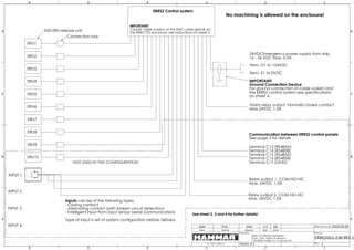
  • 1. ERRS2 Control system 24VDCEmergency power supply from ship 16 - 36 VDC Max. 0.5A Term. D1 to +24VDC Term. E1 to 0VDC ERU1 ERU4 ERU3 ERU2 ERU5 ERU6 ERU7 ERU8 ERU9 ERU10 INPUT 1 INPUT 2 INPUT 3 INPUT 4 Alarm relay output. Normally closed contact Max.24VDC 1,0A Relay output 1, COM-NO-NC Max. 24VDC 1,0A Relay output 2, COM-NO-NC Max. 24VDC 1,0A Connection box See sheet 2, 3 and 4 for further details! H20 ERU release unit No machining is allowed on the enclosure! IMPORTANT! Ground Connection Device For ground connection of cable screen and the ERRS2 control system see specifications on sheet 4 Inputs can be of the following types: - Closing contact - Alternating contact (with broken circuit detection) - Intelligent input from input sensor (serial communication) Type of input is set at system configuration before delivery. IMPORTANT! Connet cable screens at the EMC cable glands on the ERRS CP2 enclosure, see instructions on sheet 2 NOT USED IN THIS CONFIGURATION Terminal C13 (RS485A) Terminal C14 (RS485B) Terminal C15 (RS485A) Terminal C16 (RS485B) Terminal C17 (GND) Communication between ERRS2 control panels See page 3 for details Drawn Checked Approved Date: (yyyy-mm-dd) Sheet Scale Draw.No. Tel.: +46 31 709 65 50 A3 ERRS2001-238 REV 1 JoUn 2022-04-20 1:1 Rev.: 1 JoUn FrJa Sheet1 4 of A A B B C C D D 6 6 5 5 4 4 3 3 2 2 1 1 Description ERRS CP2 WIRING DIAGRAM Dumi - ship: Jadran & Biokovo CONTROL PANEL, ID = 0, SB and PS
  • 2. INSTALLATION SPECIFICATIONS FOR THE ERRS2 CONTROL PANEL ENCLOSURE: Never do any machining on the ERRS2 enclosure as this will reduce the corrosion protection of the enclosure and void the guarantee for the ERRS2 system! CONNECTION TERMINALS: Max. cable area 2.5 mm2 POWER SUPPLY: Voltage: 16 - 36 VDC, 0.5 A. FUSE: 1.0 AF 5X20 mm (fast) glass tube fuse. NETWORK ADDRESS: Switch 1 is used to give each control panel its own network address. Default setting 0. Available addresses 0 - 7. SPECIAL CONFIGURATIONS: Switch 2 -1 and switch 2 - 2 is used to set optional special configurations for the ERRS2 system. Default setting off. BACKUP BATTERY: The backup battery is a 6 VDC rechargeable accumulator. Disconnect the battery if the emergency power supply is switched off in order to increase battery life. The battery shall be changed after 5 years or earlier if a low battery warning is indicated on the system display. EMC CABLE GLANDS: The ERRS2 enclosure can be equipped with a total of 12 EMC cable glands. All cable glands have to be of EMC type that terminates the cable screen in the cable gland. 10 pc´s Cable gland M16x1.5: max. cable diameter 10 mm 2 pc´s Cable gland M20x1.5: Max. cable diameter 14 mm Special cable glands for bigger diameter cables can on request be supplied by HAMMAR. In the case that the number of available cable glands is not sufficient a cable with a higher number of wires can be used. Outputs can be grouped together in the same cable. Inputs can be grouped together in the same cable. Relay outputs and Alarm outputs can be grouped together in the same cable. Use external connection boxes to split the cable to the different targets. Special cable glands for bigger diameter cables can on request be supplied by HAMMAR. CABLES, CABLE SCREENS AND SYSTEM GROUND CONNECTION: Do not install cables for the ERRS2 system in cable groves containing high voltage cables. Screened marine approved cables shall be used for the installation. Important! All cable screens shall be terminated in the EMC cable glands on the ERRS2 enclosure. The screen for the 24VDC power supply cable shall also be connected to ground in the GROUND CONNECTION DEVICE, see details on sheet 4. The other end of all other cable screens shall be isolated from ground connection! CABLES FOR OUTPUTS: Maximum length 150 meter. For cables with a length of maximum 75 meter use 2x0.75 mm2 screened cable. For cables with a length of 75 to 150 meter use 2x1.5 mm2 screened cable. CABLES FOR RELAY OUTPUTS: Maximum length 150 meter. For cables with a length of maximum 75 meter use 2x0.75 mm2 screened cable. For cables with a length of 75 to 150 meter use 2x1.5 mm2 screened cable. CABLES FOR INPUTS: Maximum length 150 meter. Use 2x0.75 mm2 or 3x0.75 mm2 screened cable. See specifications on Sheet 3. CABLE FOR 24VDC POWER SUPPLY: Maximum length 150 meter. For cables with a length of maximum 75 meter use 2x0.75 mm2 screened cable. For cables with a length of 75 to 150 meter use 2x1.5 mm2 screened cable. Important! See Sheet 4 for specifications regarding the cable screen ground connection! CABLE FOR ALARM OUTPUT: Maximum length 150 meter. Use 2x0.75 mm2 screened cable. CABLE FOR COMMUNICATION BETWEEN CONTROL PANELS: Maximum length 1000 meter. For cable with a length of maximum 500 meter use 2x2x0.5 mm2 twisted pair, screened cable. For cable with a length of 500 to 1000 meter use 2x2x0.75 mm2 twisted pair, screened cable. Important! Connect the screen for the communication cable in one end only! The other end of the cable screen shall be isolated from ground connection. Drawn Checked Approved Date: (yyyy-mm-dd) Sheet Scale Draw.No. Tel.: +46 31 709 65 50 A3 ERRS2001-238 REV 1 JoUn 2022-04-20 1:1 Rev.: 1 JoUn FrJa Sheet2 4 of Material A A B B C C D D 6 6 5 5 4 4 3 3 2 2 1 1 Description Surface Finish: ERRS CP2 WIRING DIAGRAM Dumi - ship: Jadran & Biokovo CONTROL PANEL, ID = 0, SB and PS
  • 3. WIRING SPECIFICATIONS Drawn Checked Approved Date: (yyyy-mm-dd) Sheet Scale Draw.No. Tel.: +46 31 709 65 50 A3 ERRS2001-238 REV 1 JoUn 2022-04-20 1:1 Rev.: 1 JoUn FrJa Sheet3 4 of Material A A B B C C D D 6 6 5 5 4 4 3 3 2 2 1 1 Description Surface Finish: ERRS CP2 WIRING DIAGRAM Dumi - ship: Jadran & Biokovo CONTROL PANEL, ID = 0, SB and PS
  • 4. IMPORTANT! ERRS2 control system enclosure and cable screen connection to ships ground A good connection to the ships ground of the ERRS2 enclosure and the screens of the installed cables is important for the correct function of the ERRS2 control system. To ensure a good ground connection a "GROUND CONNECTION DEVICE" shall be installed on the power supply cable near the ERRS2 enclosure. The cable length between the "GROUND CONNECTION DEVICE" and the ERRS2 enclosure shall not be more than 4 meter. If it is not suitable to install the device on the power supply cable the "GROUND CONNECTION DEVICE" can instead be installed on one of the other cables connected to the ERRS2 enclosure. The cable length between the ERRS2 enclosure and the device shall still not be more than 4 meter. If the power supply cable is no longer than 4 meter the screen can be connected to ground at the 24VDC switchboard where the cable is connected. SELECT THE CORRECT "GROUND CONNECTION DEVICE" The "GROUND CONNECTION DEVICE" is available in two sizes: GROUND CONNECTION DEVICE M20 To be used with cables with a diameter of 6 - 12 mm, and a screen with a diameter of 4,5 - 10 mm. GROUND CONNECTION DEVICE M25 To be used with cables with a diameter of 12 - 18 mm, and a screen with a diameter of 7 - 14 mm. INSTALLATION OF "GROUND CONNECTION DEVICE": Bolt the device to the ships metal structure in such a way that a good permanent electrical connection is ensured between the device and the ships metal structure. Pass the cable through the device. Remove a length of about 20 - 30 mm of the outer isolation of the cable in such a way that the cable screen is left electrically unprotected. Position the unprotected section of the cable screen in the device so the contact fingers (inside the EMC cable gland) in the device will be in the middle of the unprotected section of the cable and in good connection with the cable screen. Tighten the compression nuts on the cable glands to fix the cable in the device. Connect the cable to the ERRS2 enclosure and make sure that the cable screen is connected properly in the EMC cable gland on the ERRS2 enclosure. Connect the wires to the terminals in the ERRS2 enclosure. GROUND CONNECTION DEVICE Drawn Checked Approved Date: (yyyy-mm-dd) Sheet Scale Draw.No. Tel.: +46 31 709 65 50 A3 ERRS2001-238 REV 1 JoUn 2022-04-20 1:1 Rev.: 1 JoUn FrJa Sheet4 4 of Material A A B B C C D D 6 6 5 5 4 4 3 3 2 2 1 1 Description Surface Finish: ERRS CP2 WIRING DIAGRAM Dumi - ship: Jadran & Biokovo CONTROL PANEL, ID = 0, SB and PS