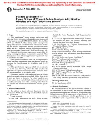
SlideShare une entreprise Scribd logo
1  sur  8
Télécharger pour lire hors ligne
Designation: A 234/A 234M – 00a Used in USDOE-NE Standards
An American National Standard
Standard Specification for
Piping Fittings of Wrought Carbon Steel and Alloy Steel for
Moderate and High Temperature Service1
This standard is issued under the fixed designation A 234/A 234M; the number immediately following the designation indicates the year
of original adoption or, in the case of revision, the year of last revision. A number in parentheses indicates the year of last reapproval.
A superscript epsilon (e) indicates an editorial change since the last revision or reapproval.
This standard has been approved for use by agencies of the Department of Defense.
1. Scope
1.1 This specification2
covers wrought carbon steel and
alloy steel fittings of seamless and welded construction covered
by the latest revision of ASME B16.9, B16.11, B16.28, MSS
SP-79, and MSS SP-95. These fittings are for use in pressure
piping and in pressure vessel fabrication for service at moder-
ate and elevated temperatures. Fittings differing from these
ASME and MSS standards shall be furnished in accordance
with Supplementary Requirement S58 of Specification A 960.
1.2 Optional supplementary requirements are provided for
fittings where a greater degree of examination is desired. When
desired, one or more of these supplementary requirements may
be specified in the order.
1.3 This specification does not cover cast welding fittings or
fittings machined from castings. Cast steel welding fittings are
governed by Specifications A 216/A 216M and A 217/
A 217M.
1.4 This specification is expressed in both inch-pound units
and in SI units. However, unless the order specifies the
applicable “M” specification designation (SI units), the mate-
rial shall be furnished to inch-pound units.
1.5 The values stated in either inch-pound units or SI units
are to be regarded separately as standard. Within the text, the
SI units are shown in brackets. The values stated in each
system are not exact equivalents; therefore, each system must
be used independently of the other. Combining values from the
two systems may result in nonconformance with the specifi-
cation.
2. Referenced Documents
2.1 In addition to those reference documents listed in
Specification A 960, the following list of standards apply to
this specification.
2.2 ASTM Standards:
A 216/A 216M Specification for Steel Castings, Carbon,
Suitable for Fusion Welding, for High-Temperature Ser-
vice3
A 217/A 217M Specification for Steel Castings, Martensi-
tic Stainless and Alloy, for Pressure-Containing Parts
Suitable for High-Temperature Service3
A 960 Specification for Common Requirements for
Wrought Steel Piping Fittings4
2.3 ASME Standards:5
B16.9 Steel Butt-Welding Fittings
B16.11 Forged Steel Fittings, Socket Welding and Threaded
B16.28 Wrought Steel Butt-Welding Short Radius Elbows
and Returns
2.4 ASME Boiler and Pressure Vessel Code:5
Section V Nondestructive Examination
Section VIII, Division 1, Pressure Vessels
Section IX Welding Qualifications
2.5 MSS Standards:6
MSS SP-25 Standard Marking System for Valves, Fittings,
Flanges, and Unions
MSS SP-79 Socket Welding Reducer Inserts
MSS SP-95 Swage(d) Nipples and Bull Plugs
2.6 ASNT Standard:
SNT-TC-1A(1984) Recommended Practice for Nondestruc-
tive Testing Personnel Qualification and Certification7
3. Ordering Information
3.1 See Specification A 960.
4. General Requirements
4.1 Product furnished to this specification shall conform to
the requirements of Specification A 960, including any supple-
mentary requirements that are indicated in the purchase order.
Failure to comply with the requirements of Specification A 960
constitutes non-conformance with this specification. In case of
a conflict between the requirements of this specification and
1
This specification is under the jurisdiction of ASTM Committee A01 on Steel,
Stainless Steel, and Related Alloys and is the direct responsibility of Subcommittee
A01.22 on Steel Forgings and Wrought Fittings for Piping Applications and Bolting
Materials for Piping and Special Purpose Applications.
Current edition approved Dec. 10, 2000. Published March 2001. Originally
published as A 234 – 40 T. Last previous edition A 234/A 234M – 00.
2
For ASME Boiler and Pressure Vessel Code applications see related Specifi-
cation SA-234 in Section II of that Code.
3
Annual Book of ASTM Standards, Vol 01.02.
4
Annual Book of ASTM Standards, Vol 01.01.
5
Available from ASME International, Three Park Avenue, New York, NY
10016–5990.
6
Available from Manufacturers Standardization Society of the Valve and Fittings
Industry, 1815 N. Fort Myer Drive, Arlington, VA 22209.
7
Available from American Society for Nondestructive Testing, 4153 Arlingate
Plaza, Columbus, OH 43228-0518.
1
Copyright © ASTM, 100 Barr Harbor Drive, West Conshohocken, PA 19428-2959, United States.
NOTICE: This standard has either been superseded and replaced by a new version or discontinued.
Contact ASTM International (www.astm.org) for the latest information.
Specification A 960, this specification shall prevail.
5. Materials
5.1 The material for fittings shall consist of killed steel,
forgings, bars, plates, seamless or fusion-welded tubular prod-
ucts with filler metal added and shall conform to the chemical
requirements of Table 1. Unless otherwise specified for carbon
steel plates, the steel may be made to either coarse grain or fine
grain practice. Grade WP9 shall be made to fine grain practice.
5.2 A starting material specification that specifically re-
quires the addition of any element beyond those listed for the
materials in Table 1 for the applicable grade of material is not
permitted. This does not preclude the use of deoxidizers or the
judicious use of elements for grain size control.
6. Manufacture
6.1 Forging or shaping operations may be performed by
hammering, pressing, piercing, extruding, upsetting, rolling,
bending, fusion welding, machining, or by a combination of
two or more of these operations. The forming procedure shall
be so applied that it will not produce injurious imperfections in
the fittings.
NOTE 1—Fittings NPS-4 and under may be machined from hot-forged
or rolled, cold-sized, and straightened bar stock having the chemical
composition of the Grade in Table 1 and the mechanical properties of the
Grade in Table 2. Heat treatment shall be in accordance with Section 7. All
caps machined from bar stock shall be examined by liquid penetrant or
magnetic particle in accordance with S52 or S53 in Specification A 960.
6.2 All welds including welds in tubular products from
which fittings are made shall be (1) made by welders, welding
operators, and welding procedures qualified under the provi-
sions of ASME Section IX, (2) heat treated in accordance with
Section 7 of this specification, and (3) radiographically exam-
ined throughout the entire length of each weld in accordance
with Article 2, ASME Section V with acceptance limits in
accordance with Paragraph UW-51 of ASME Section VIII,
Division 1 of the ASME Boiler & Pressure Vessel Code. In
place of radiographic examination, welds may be ultrasonically
examined in accordance with Appendix 12 of Section VIII. The
NDE of welds in Grades WPB, WPC, WP1, WP11 Class 1,
WP11 Class 2, WP11 Class 3, WP12 Class 1, WP12 Class 2,
and WPR may be performed either prior to or after forming.
NDE of welds in Grades WP5, WP9, WP91, WP911, WP22
Class 1, and WP22 Class 3 shall be done after forming.
6.3 Personnel performing NDE examinations shall be quali-
fied in accordance with SNT-TC-1A.
6.4 The welded joints of the fittings shall be finished in
accordance with the requirements of Paragraph UW-35 ( a) of
ASME Section VIII, Division 1.
TABLE 1 Chemical Requirements
NOTE 1—All requirements are maximum unless otherwise indicated.
NOTE 2—Where an ellipsis (...) appears in this table, there is no requirement.
Grade and
Marking
SymbolA
Composition, %
Carbon Manganese
Phospho-
rus, max
Sulfur,
max
Silicon Chromium Molybdenum Nickel Copper Others
WPBB,C,D,E,F
0.30 max 0.29–1.06 0.050 0.058 0.10 min 0.40 max 0.15 max 0.40 max 0.40 max Vanadium 0.08 max
Columbium 0.02 max
WPCC,D,E,F
0.35 max 0.29–1.06 0.050 0.058 0.10 min 0.40 max 0.15 max 0.40 max 0.40 max Vanadium 0.08 max
Columbium 0.02 max
WP1 0.28 max 0.30–0.90 0.045 0.045 0.10–0.50 . . . 0.44–0.65 . . . . . . . . .
WP12 CL1, 0.05–0.20 0.30–0.80 0.045 0.045 0.60 max 0.80–1.25 0.44–0.65 . . . . . . . . .
WP12 CL2 . . .
WP11 CL1 0.05–0.15 0.30–0.60 0.030 0.030 0.50–1.00 1.00–1.50 0.44–0.65 . . . . . . . . .
WP11 CL2, 0.05–0.20 0.30–0.80 0.040 0.040 0.50–1.00 1.00–1.50 0.44–0.65 . . . . . . . . .
WP11 CL3 . . .
WP22 CL1, 0.05–0.15 0.30–0.60 0.040 0.040 0.50 max 1.90–2.60 0.87–1.13 . . . . . . . . .
WP22 CL3 . . .
WP5 CL1, 0.15 max 0.30–0.60 0.040 0.030 0.50 max 4.0–6.0 0.44–0.65 . . . . . . . . .
WP5 CL3 . . .
WP9 CL1,
WP9 CL3
0.15 max 0.30–0.60 0.030 0.030 1.00 max 8.0–10.0 0.90–1.10 . . . . . . . . .
WPR 0.20 max 0.40–1.06 0.045 0.050 . . . . . . . . . 1.60–2.24 0.75–1.25 . . .
WP91 0.08–0.12 0.30–0.60 0.020 0.010 0.20–0.50 8.0–9.5 0.85–1.05 0.40 max . . . Vanadium 0.18–0.25
Columbium 0.06–0.10
Nitrogen 0.03–0.07
Aluminum 0.04 max
WP911 0.09–0.13 0.30–0.60 0.020 0.010 0.10–0.50 8.5–10.5 0.90–1.10 0.40 max . . . Vanadium 0.18–0.25
Columbium 0.060–0.10
Nitrogen 0.04–0.09
Aluminum 0.04 max
Boron 0.0003–0.006
Tungsten 0.90–1.10
A
When fittings are of welded construction, the grade and marking symbol shown above shall be supplemented by letter “W”.
B
Fittings made from bar or plate may have 0.35 max carbon.
C
Fittings made from forgings may have 0.35 max carbon and 0.35 max silicon with no minimum.
D
For each reduction of 0.01 % below the specified carbon maximum, an increase of 0.06 % manganese above the specified maximum will be permitted, up to a
maximum of 1.35 %.
E
The sum of Copper, Nickel, Chromium, and Molybdenum shall not exceed 1.00 %.
F
The sum of Chromium and Molybdenum shall not exceed 0.32 %.
A 234/A 234M
2
6.5 All butt-weld tees manufactured by cold-forming meth-
od(s) shall be liquid penetrant or magnetic particle examined
by one of the methods specified in Supplementary Requirement
S52 or S53 in Specification A 960. This examination shall be
performed after final heat treat. Only the side wall area of the
tees need be examined. This area is defined by a circle that
covers the area from the weld bevel of the branch outlet to the
center line of the body or run. Internal and external surfaces
shall be examined when size permits accessibility. No cracks
shall be permitted. Other imperfections shall be treated in
accordance with Section 13 on Surface Quality. After the
removal of any crack, the tee(s) shall be re-examined by the
original method. Acceptable tees shall be marked with the
symbol PT or MT, as applicable, to indicate compliance.
7. Heat Treatment
7.1 Heat Treatment Procedures—Fittings, after forming at
an elevated temperature, shall be cooled to a temperature
below the critical range under suitable conditions to prevent
injuries by too rapid cooling, but in no case more rapidly than
the cooling rate in still air. Heat treatment temperatures
specified are metal (part) temperatures. Heat-treated fittings
shall be treated according to paragraph 7 in Specification
A 960.
7.2 WPB, WPC, and WPR Fittings:
7.2.1 Hot-formed WPB, WPC, and WPR fittings upon
which the final forming operation is completed at a temperature
above 1150°F [620°C] and below 1800°F [980°C] need not be
TABLE 2 Tensile Requirements
NOTE 1—Where an ellipsis (...) appears in this table, there is no requirement.
Grade and Marking Symbol WPB
WPC,
WP11 CL2,
WP12 CL2
WP1
WP11 CL1,
WP22 CL1,
WP5 CL1
WP9 CL1
WPR
WP11 CL3,
WP22 CL3
WP5 CL3
WP9 CL3
WP91 WP911 WP12 CL1
Tensile strength, range ksi [MPa] 60–85
[415–585]
70–95
[485–655]
55–80
[380–550]
60–85
[415–585]
63–88
[435–605]
75–100
[520–690]
85–110
[585–760]
90–120
[620–840]
60–85
[415–585]
Yield strength, min, ksi [MPa]
(0.2 % offset or 0.5 %
extension-
under-load)
35 [240] 40 [275] 30 [205] 30 [205] 46 [315] 45 [310] 60 [415] 64 [440] 32 [220]
Elongation Requirements
Grades
All Grades except WPR,
WP91, and WP911
WPR
WP91
WP911
Longi-
tudinal
Trans-
verse
Longi-
tudinal
Trans-
verse
Longi-
tudinal
Trans-
verse
Elongation:
Standard round specimen, or small proportional specimen, min % in 4 D 22 14 20 . . . 20 . . .
Rectangular specimen for wall thickness 5⁄16 in. [7.94 mm] and over,
and for all small sizes tested in full section; min % in 2 in. [50 mm]
30 20A
28 . . . . . . . . .
Rectangular specimen for wall thickness less than 5⁄16 in. [7.94 mm];
min % in 2 in. [50 mm] (1⁄2-in. [12.7-mm] wide specimen)
B B B
. . . . . . . . .
A
WPB and WPC fittings manufactured from plate shall have a minimum elongation of 17 %.
B
For each 1⁄32 in. [0.79 mm] decrease in wall thickness below 5⁄16 in. [7.94 mm], a deduction of 1.5 % for longitudinal and 1.0 % for transverse from the values shown
above is permitted. The following table gives the minimum value for various wall thicknesses.
Wall Thickness
Grades
All Grades except WPR, WP91 and WP911 WPR WP91 and WP911
in. [mm] Longitudinal Transverse Longitudinal Longitudinal
5⁄16 (0.312) 7.94 30.0 20.0 28.0 20
9⁄32 (0.281) 7.14 28.5 19.0 26.5 19
1⁄4 (0.250) 6.35 27.0 18.0 25.0 18
7⁄32 (0.219) 5.56 25.5 . . . 23.5 17
3⁄16 (0.188) 4.76 24.0 . . . 22.0 16
5⁄32 (0.156) 3.97 22.5 . . . 20.5 15
1⁄8 (0.125) 3.17 21.0 . . . 19.0 14
3⁄32 (0.094) 2.38 19.5 . . . 17.5 13
1⁄16 (0.062) 1.59 18.0 . . . 16.0 12
Note—This table gives the computed minimum % elongation value for each 1⁄32 in. [0.79 mm] decrease in wall thickness. Where the wall thickness lies between two
values above, the minimum elongation value is determined by the following equations:
Direction of Test Equation
Longitudinal E= 48t + 15.00
Transverse E= 32t + 10.00
where:
E = elongation in 2 in. or [50 mm], %, and
t = actual thickness of specimen, in. [mm].
A 234/A 234M
3
heat treated provided they are cooled in still air.
7.2.2 Hot-formed or forged WPB, WPC, and WPR fittings
finished at temperature in excess of 1800°F [980°C] shall
subsequently be annealed, normalized, or normalized and
tempered. Hot-forged fittings NPS 4 or smaller need not be
heat treated.
7.2.3 WPB, WPC, and WPR fittings produced by locally
heating a portion of the fitting stock to any temperature for
forming shall be subsequently annealed, normalized, or nor-
malized and tempered. Fittings such as elbows, tees, header
tees, reducers and lap joint stub ends, NPS 12 and under, shall
not require heat treatment after forming a locally heated
portion of the fitting.
7.2.4 Cold-formed WPB, WPC, and WPR fittings, upon
which the final forming operation is completed at a temperature
below 1150°F [620°C], shall be normalized, or shall be stress
relieved at 1100 to 1275°F [595 to 690°C].
7.2.5 WPB, WPC, and WPR fittings produced by fusion
welding and having a nominal wall thickness at the welded
joint of 3⁄4 in. [19 mm] or greater shall be post-weld heat treated
at 1100 to 1250°F [595 to 675°C], or in accordance with 7.2.6.
7.2.6 At the option of the manufacturer, WPB and WPC
fittings produced by any of the methods in Section 6 may be
annealed, normalized, or normalized and tempered.
7.3 Fittings Other than WPB, WPC, and WPR:
7.3.1 Fittings of Grades WP1, WP11 Class 1, WP11 Class 2,
WP11 Class 3, WP12 Class 1, WP12 Class 2, WP22 Class 1,
WP22 Class 3, WP5, and WP9 shall be furnished in the
full-annealed, isothermal-annealed, or normalized and tem-
pered condition. If normalized and tempered, the tempering
temperature for WP11 Class 1, WP11 Class 2, WP11 Class 3,
WP12 Class 1, and WP12 Class 2 shall not be less than 1150°F
[620°C]; for Grades WP5, WP9, WP22 Class 1, and WP22
Class 3 the tempering temperature shall not be less than
1250°F [675°C].
7.3.2 Fittings of Grades WP1, WP12 Class 1, or WP12
Class 2 either hot formed or cold formed may be given a final
heat treatment at 1200°F [650°C] instead of the heat treatment
specified in 7.3.1.
7.3.3 Fittings in all thicknesses produced by fusion welding
after the heat treatment specified in 7.3.1 shall be post-weld
heat treated at a temperature not less than prescribed above for
tempering except that Grade WP1 is required to be post-weld
heat treated only when the nominal wall thickness at the
welded joint is 1⁄2 in. [13 mm] or greater.
7.3.4 Except when Supplementary Requirement S1 is speci-
fied by the purchaser, Grade WP91 shall be normalized at
1900°F [1040°C] minimum, and 2000°F [1095°C] maximum,
and tempered at 1350°F [730°C] minimum as a final heat
treatment.
7.4 WPB and WPC Fittings Made from Bar— Cold-finished
bars reduced in cross-sectional area more than 10 % by cold
drawing or cold rolling are not acceptable for use in the
manufacture of these fittings unless the bars have been either
stress relieved in the temperature range of 1100 to 1250°F [595
to 675°C], normalized, normalized and tempered, or fully
annealed. Mechanical testing must be performed subsequent to
the final heat-treating operation.
7.5 Liquid quenching followed by tempering shall be per-
mitted for all grades when approved by the purchaser. Mini-
mum tempering temperature shall be 1100°F [595°C] for WPB,
WPC, and WPR, 1150°F [620°C] for Grades WP1, WP11
Class 1, WP11 Class 2, WP11 Class 3, WP 12 Class 1, and
WP12 Class 2 and 1250°F [675°C] for Grades WP5, WP9,
WP22 Class 1, and WP22 Class 3, and 1350°F (730°C) for
Grade WP91 and WP911.
8. Chemical Composition
8.1 The chemical composition of each cast or heat used
shall be determined and shall conform to the requirements of
the chemical composition for the respective materials listed in
Table 1. The ranges as shown have been expanded to include
variations of the chemical analysis requirements that are listed
in the various specifications for the starting materials (pipe,
tube, plate, bar, and forgings) normally used in the manufac-
turing of fittings to this specification.
8.2 The steel shall not contain any unspecified elements for
the ordered grade to the extent that it conforms to the
requirements of another grade for which that element is a
specified element having a required minimum content.
8.3 Weld metal used in the construction of carbon-steel
fittings shall be mild steel analysis No. A1 of Table QW-442,
Section IX of the ASME Boiler and Pressure Vessel Code, No.
A2 may be used for Grade WPCW.
8.4 The molybdenum and chromium content of the depos-
ited weld metal of alloy steel fittings shall be within the same
percentage range as permitted for the base metal.
9. Tensile Requirements
9.1 The tensile properties of the fitting material shall con-
form to the requirements listed in Table 2.
9.1.1 Specimens cut either longitudinally or transversely
shall be acceptable for the tension test.
9.1.2 While Table 2 specifies elongation requirements for
both longitudinal and transverse specimens, it is not the intent
that both requirements apply simultaneously. Instead, it is
intended that only the elongation requirement that is appropri-
ate for the specimen used be applicable.
9.2 One tension test shall be made on each heat of material
and in the same condition of heat treatment as the finished
fittings it represents. The sample thickness shall not vary more
than 1⁄4 in. [6 mm] from the fitting wall thickness it represents.
9.3 When cold-formed fittings are furnished, samples of the
raw material shall be normalized or stress relieved as required
in 7.2.4. Tension tests conducted on these heat-treated samples
shall be considered to be the tensile properties of the cold-
formed fittings.
9.4 Records of the tension tests shall be certification that the
material of the fitting meets the tensile requirements of this
specification provided the heat treatments are the same. If the
raw material was not tested, or the fitting is not in the same
condition of heat treatment, the fitting manufacturer shall
perform the required test on material representative of the
finished fitting from each heat of starting material.
10. Hardness
10.1 Fittings shall be capable of meeting the following
A 234/A 234M
4
hardness requirements, if tested:
10.1.1 Fittings of Grades WP5, WP9, and WPR—217 HB
maximum.
10.1.2 Fittings of Grade WP91 and WP911—248 HB maxi-
mum.
10.1.3 Fittings of all other grades—197 HB maximum.
10.2 When actual hardness testing of the fittings is required,
see Supplementary Requirement S57 in Specification A 960.
11. Hydrostatic Tests
11.1 See Specification A 960.
12. Dimensions
12.1 Butt-welding fittings and butt-welding short radius
elbows and returns purchased in accordance with this specifi-
cation shall conform to the dimensions and tolerances given in
the latest revision of ANSI B16.9 and B16.28, respectively.
Steel socket-welding and threaded fittings purchased in accor-
dance with this specification shall conform to the sizes, shapes,
dimensions, and tolerances specified in the latest revision of
ANSI B16.11 or MSS SP-79.
12.2 Fittings of size or shape differing from these standards,
but meeting all other requirements of this specification may be
furnished in accordance with Supplementary Requirement S58
in Specification A 960.
13. Surface Quality
13.1 See Specification A 960.
14. Repair by Welding
14.1 See Specification A 960.
15. Inspection
15.1 See Specification A 960.
15.2 Other tests, when required by agreement, shall be made
from material of the lots covered in the order.
16. Rejection and Rehearing
16.1 Material that fails to conform to the requirements of
this specification may be rejected. Rejection should be reported
to the producer or supplier promptly in writing. In case of
dissatisfaction with the results of the tests, the producer or
supplier may make claim for a rehearing.
16.2 Fittings that develop defects in shopworking or appli-
cation operations may be rejected. Upon rejection, the manu-
facturer shall be notified promptly in writing.
17. Certification
17.1 When requested by the purchaser, the manufacturer
shall provide a certificate of compliance to this specification. In
addition, if requested to provide test reports, the manufacturer
shall also provide the following where applicable:
17.1.1 Chemical analysis results, Section 8 (Table 1). When
the amount of an element is less than 0.02 %, the analysis for
that element may be reported as “<0.02 %.”
17.1.2 Tensile property results, Section 9 (Table 2), report
the yield strength and ultimate strength in ksi [MPa] and
elongation in percent,
17.1.3 Hardness acceptable in accordance with Section 10,
17.1.4 Type heat treatment, if any, Section 7,
17.1.5 Seamless or welded,
17.1.6 Starting material, specifically pipe, plate, etc.,
17.1.7 Statement regarding radiographic or ultrasonic ex-
amination, 6.2, and
17.1.8 Any supplemental testing required by the purchase
order.
17.2 Letters of compliance and test reports shall state the
specification number, year of issue, revision letter (if any),
grade and class of the fittings.
18. Product Marking
18.1 All fittings shall have the prescribed information
stamped or otherwise suitably marked on each fitting in
accordance with the Standard Marking System for Valves,
Fittings, Flanges and Unions (MSS SP-25, latest edition).
18.2 The prescribed information for butt-welding fittings
shall be: The manufacturer’s name or trademark (see Note 2),
schedule number or nominal wall thickness designation, size,
fitting designation in accordance with Annex A1 and the heat
number or manufacturer’s heat identification.
NOTE 2—For purposes of identification marking, the manufacturer is
considered the organization that certifies the piping component complies
with this specification.
18.3 The prescribed information for threaded or socket-
welding fittings shall be: The manufacturer’s name or trade-
mark (see Note 2), pressure class or schedule number and
fitting designation in accordance with Annex A1, and the heat
number or the manufacturer’s heat identification.
18.4 Specification number, year of issue and revision letter
are not required to be marked on fittings.
18.5 Bar Coding—In addition to the requirements in 18.1,
18.2, 18.3 and 18.4, bar coding is acceptable as a supplemental
identification method. The purchaser may specify in the order
a specific bar coding system to be used. The bar coding system,
if applied at the discretion of the supplier, should be consistent
with one of the published industry standards for bar coding. If
used on small fittings, the bar code may be applied to the box
or a substantially applied tag.
19. Keywords
19.1 pipe fittings—steel; piping applications; pressure con-
taining parts; pressure vessel service; temperature service
applications—elevated
A 234/A 234M
5
SUPPLEMENTARY REQUIREMENTS
These requirements shall not be considered unless specified in the order, in which event, the
supplementary requirements specified shall be made at the place of manufacture, unless otherwise
agreed upon, at the purchaser’s expense. The test specified shall be witnessed by the purchaser’s
inspector before shipment of material, if so specified in the order.
S1. Alternative Heat Treatment—Grade WP91
S1.1 Grade WP91 shall be normalized in accordance with
7.3.4 and tempered at a temperature, to be specified by the
purchaser, less than 1350°F [730°C]. It shall be the purchaser’s
responsibility to subsequently temper the entire fitting at
1350°F [730°C] minimum. All mechanical tests shall be made
on material heat treated in accordance with 7.3.4. The certifi-
cation shall reference this supplementary requirement indicat-
ing the actual tempering temperature applied. The notation
“S1’’ shall be included with the required marking of the fitting.
S2. Restricted Vanadium Content
S2.1 The vanadium content of the fittings shall not exceed
0.03 %.
S3. Carbon Equivalent
S3.1 For grades WPB and WPC, the maximum carbon
equivalent (C.E.), based on heat analysis and the following
formula, shall be 0.50.
C.E.5 C1
Mn
6 1
Cr 1Mo 1 V
5 1
Ni 1Cu
15
S3.2 A lower maximum carbon equivalent may be agreed
upon between the purchaser and the supplier.
S3.3 The C.E. shall be reported on the test report.
A 234/A 234M
6
ANNEX
(Mandatory Information)
A1. FITTING DESIGNATION FOR MARKING PURPOSES
TABLE A1.1 Fitting Designation for Marking Purposes
Grade Class Construction Mandatory Marking
WPB W (Welded construction) WPBWA
S (Seamless construction) WPB
WPC W (Welded construction) WPCWA
S (Seamless construction) WPC
WP1 W (Welded construction) WP1WA
S (Seamless construction) WP1
WP12 CL1 W (Welded construction) WP12 CL1WA
S (Seamless construction) WP12 CL1
CL2 W (Welded construction) WP12 CL2WA
S (Seamless construction) WP12 CL2
WP11 CL1 W (Welded construction) WP11 CL1WA
S (Seamless construction) WP11 CL1
CL2 W (Welded construction) WP11 CL2WA
S (Seamless construction) WP11 CL2
CL3 W (Welded construction) WP11 CL3WA
S (Seamless construction) WP11 CL3
WP22 CL1 W (Welded construction) WP22 CL1WA
S (Seamless construction) WP22 CL1
CL3 W (Welded construction) WP22 CL3WA
S (Seamless construction) WP22 CL3
WP5 CL1 W (Welded construction) WP5 CL1WA
S (Seamless construction) WP5 CL1
CL3 W (Welded construction) WP5 CL3 WA
S (Seamless construction) WP5 CL3
WP9 CL1 W (Welded construction) WP9 CL1 WA
S (Seamless construction) WP9 CL1
CL3 W (Welded construction) WP9 CL3 WA
S (Seamless construction) WP9 CL3
WPR W (Welded construction) WPR WA
S (Seamless construction) WPR
WP91 W (Welded construction) WP91WA
S (Seamless construction) WP91
A
Add “U” to marking if welds are ultrasonic inspected in lieu of radiography.
A 234/A 234M
7
The American Society for Testing and Materials takes no position respecting the validity of any patent rights asserted in connection
with any item mentioned in this standard. Users of this standard are expressly advised that determination of the validity of any such
patent rights, and the risk of infringement of such rights, are entirely their own responsibility.
This standard is subject to revision at any time by the responsible technical committee and must be reviewed every five years and
if not revised, either reapproved or withdrawn. Your comments are invited either for revision of this standard or for additional standards
and should be addressed to ASTM Headquarters. Your comments will receive careful consideration at a meeting of the responsible
technical committee, which you may attend. If you feel that your comments have not received a fair hearing you should make your
views known to the ASTM Committee on Standards, at the address shown below.
This standard is copyrighted by ASTM, 100 Barr Harbor Drive, PO Box C700, West Conshohocken, PA 19428-2959, United States.
Individual reprints (single or multiple copies) of this standard may be obtained by contacting ASTM at the above address or at
610-832-9585 (phone), 610-832-9555 (fax), or service@astm.org (e-mail); or through the ASTM website (www.astm.org).
A 234/A 234M
8

Contenu connexe

Similaire à A 234 – A 234M – 00 ;QTIZNC0WMEE_.pdf

acero norma A727 a727m
acero norma A727 a727macero norma A727 a727m
acero norma A727 a727m
Mario Espinosa
 
A694 forgings for flanges, fittings, valves, hi press trans
A694 forgings for flanges, fittings, valves, hi press transA694 forgings for flanges, fittings, valves, hi press trans
A694 forgings for flanges, fittings, valves, hi press trans
JairoFranciscoArroyo
 
B16 c360 free-cutting brass rod, bar and shapes for use in screw machines1
B16 c360  free-cutting brass rod, bar and shapes for use in screw machines1B16 c360  free-cutting brass rod, bar and shapes for use in screw machines1
B16 c360 free-cutting brass rod, bar and shapes for use in screw machines1
Yirlany Mesén Mejías
 
Saes w-016-welding special corrosion materials
Saes w-016-welding special corrosion materialsSaes w-016-welding special corrosion materials
Saes w-016-welding special corrosion materials
abhi10apr
 
A 53 – A 53M – 00 ;QTUZLTAW.pdf
A 53 – A 53M – 00  ;QTUZLTAW.pdfA 53 – A 53M – 00  ;QTUZLTAW.pdf
A 53 – A 53M – 00 ;QTUZLTAW.pdf
ssuser4df039
 
A493 09(2013) standard specification for stainless steel wire and wire rods f...
A493 09(2013) standard specification for stainless steel wire and wire rods f...A493 09(2013) standard specification for stainless steel wire and wire rods f...
A493 09(2013) standard specification for stainless steel wire and wire rods f...
diep phan hoang
 

Similaire à A 234 – A 234M – 00 ;QTIZNC0WMEE_.pdf (18)

A105 a105m − 14
A105 a105m − 14A105 a105m − 14
A105 a105m − 14
 
A036
A036A036
A036
 
acero norma A727 a727m
acero norma A727 a727macero norma A727 a727m
acero norma A727 a727m
 
A694 forgings for flanges, fittings, valves, hi press trans
A694 forgings for flanges, fittings, valves, hi press transA694 forgings for flanges, fittings, valves, hi press trans
A694 forgings for flanges, fittings, valves, hi press trans
 
Astm a128a-128m-93-reapproved-2003
Astm a128a-128m-93-reapproved-2003Astm a128a-128m-93-reapproved-2003
Astm a128a-128m-93-reapproved-2003
 
Asme section ii a sa 414 sa-414 m
Asme section ii a sa 414 sa-414 mAsme section ii a sa 414 sa-414 m
Asme section ii a sa 414 sa-414 m
 
ASTM_A36.pdf
ASTM_A36.pdfASTM_A36.pdf
ASTM_A36.pdf
 
ASTM A249
ASTM A249ASTM A249
ASTM A249
 
A31
A31A31
A31
 
B16 c360 free-cutting brass rod, bar and shapes for use in screw machines1
B16 c360  free-cutting brass rod, bar and shapes for use in screw machines1B16 c360  free-cutting brass rod, bar and shapes for use in screw machines1
B16 c360 free-cutting brass rod, bar and shapes for use in screw machines1
 
Astm a36
Astm a36Astm a36
Astm a36
 
A240
A240A240
A240
 
Astm a409 a409-m-01(r05)
Astm a409 a409-m-01(r05)Astm a409 a409-m-01(r05)
Astm a409 a409-m-01(r05)
 
Saes w-016-welding special corrosion materials
Saes w-016-welding special corrosion materialsSaes w-016-welding special corrosion materials
Saes w-016-welding special corrosion materials
 
A778
A778A778
A778
 
A 53 – A 53M – 00 ;QTUZLTAW.pdf
A 53 – A 53M – 00  ;QTUZLTAW.pdfA 53 – A 53M – 00  ;QTUZLTAW.pdf
A 53 – A 53M – 00 ;QTUZLTAW.pdf
 
A493 09(2013) standard specification for stainless steel wire and wire rods f...
A493 09(2013) standard specification for stainless steel wire and wire rods f...A493 09(2013) standard specification for stainless steel wire and wire rods f...
A493 09(2013) standard specification for stainless steel wire and wire rods f...
 
A449 equivalente a grado 5
A449 equivalente a grado 5A449 equivalente a grado 5
A449 equivalente a grado 5
 

Dernier

Call Girls in Ramesh Nagar Delhi 💯 Call Us 🔝9953056974 🔝 Escort Service
Call Girls in Ramesh Nagar Delhi 💯 Call Us 🔝9953056974 🔝 Escort ServiceCall Girls in Ramesh Nagar Delhi 💯 Call Us 🔝9953056974 🔝 Escort Service
Call Girls in Ramesh Nagar Delhi 💯 Call Us 🔝9953056974 🔝 Escort Service
9953056974 Low Rate Call Girls In Saket, Delhi NCR
 
Call Now ≽ 9953056974 ≼🔝 Call Girls In New Ashok Nagar ≼🔝 Delhi door step de...
Call Now ≽ 9953056974 ≼🔝 Call Girls In New Ashok Nagar  ≼🔝 Delhi door step de...Call Now ≽ 9953056974 ≼🔝 Call Girls In New Ashok Nagar  ≼🔝 Delhi door step de...
Call Now ≽ 9953056974 ≼🔝 Call Girls In New Ashok Nagar ≼🔝 Delhi door step de...
9953056974 Low Rate Call Girls In Saket, Delhi NCR
 
Call Girls In Bangalore ☎ 7737669865 🥵 Book Your One night Stand
Call Girls In Bangalore ☎ 7737669865 🥵 Book Your One night StandCall Girls In Bangalore ☎ 7737669865 🥵 Book Your One night Stand
Call Girls In Bangalore ☎ 7737669865 🥵 Book Your One night Stand
amitlee9823
 
Cara Menggugurkan Sperma Yang Masuk Rahim Biyar Tidak Hamil
Cara Menggugurkan Sperma Yang Masuk Rahim Biyar Tidak HamilCara Menggugurkan Sperma Yang Masuk Rahim Biyar Tidak Hamil
Cara Menggugurkan Sperma Yang Masuk Rahim Biyar Tidak Hamil
Cara Menggugurkan Kandungan 087776558899
 

Dernier (20)

Call Girls in Ramesh Nagar Delhi 💯 Call Us 🔝9953056974 🔝 Escort Service
Call Girls in Ramesh Nagar Delhi 💯 Call Us 🔝9953056974 🔝 Escort ServiceCall Girls in Ramesh Nagar Delhi 💯 Call Us 🔝9953056974 🔝 Escort Service
Call Girls in Ramesh Nagar Delhi 💯 Call Us 🔝9953056974 🔝 Escort Service
 
Thermal Engineering-R & A / C - unit - V
Thermal Engineering-R & A / C - unit - VThermal Engineering-R & A / C - unit - V
Thermal Engineering-R & A / C - unit - V
 
KubeKraft presentation @CloudNativeHooghly
KubeKraft presentation @CloudNativeHooghlyKubeKraft presentation @CloudNativeHooghly
KubeKraft presentation @CloudNativeHooghly
 
Call Now ≽ 9953056974 ≼🔝 Call Girls In New Ashok Nagar ≼🔝 Delhi door step de...
Call Now ≽ 9953056974 ≼🔝 Call Girls In New Ashok Nagar  ≼🔝 Delhi door step de...Call Now ≽ 9953056974 ≼🔝 Call Girls In New Ashok Nagar  ≼🔝 Delhi door step de...
Call Now ≽ 9953056974 ≼🔝 Call Girls In New Ashok Nagar ≼🔝 Delhi door step de...
 
Call Girls Wakad Call Me 7737669865 Budget Friendly No Advance Booking
Call Girls Wakad Call Me 7737669865 Budget Friendly No Advance BookingCall Girls Wakad Call Me 7737669865 Budget Friendly No Advance Booking
Call Girls Wakad Call Me 7737669865 Budget Friendly No Advance Booking
 
Call Girls In Bangalore ☎ 7737669865 🥵 Book Your One night Stand
Call Girls In Bangalore ☎ 7737669865 🥵 Book Your One night StandCall Girls In Bangalore ☎ 7737669865 🥵 Book Your One night Stand
Call Girls In Bangalore ☎ 7737669865 🥵 Book Your One night Stand
 
(INDIRA) Call Girl Aurangabad Call Now 8617697112 Aurangabad Escorts 24x7
(INDIRA) Call Girl Aurangabad Call Now 8617697112 Aurangabad Escorts 24x7(INDIRA) Call Girl Aurangabad Call Now 8617697112 Aurangabad Escorts 24x7
(INDIRA) Call Girl Aurangabad Call Now 8617697112 Aurangabad Escorts 24x7
 
chapter 5.pptx: drainage and irrigation engineering
chapter 5.pptx: drainage and irrigation engineeringchapter 5.pptx: drainage and irrigation engineering
chapter 5.pptx: drainage and irrigation engineering
 
FEA Based Level 3 Assessment of Deformed Tanks with Fluid Induced Loads
FEA Based Level 3 Assessment of Deformed Tanks with Fluid Induced LoadsFEA Based Level 3 Assessment of Deformed Tanks with Fluid Induced Loads
FEA Based Level 3 Assessment of Deformed Tanks with Fluid Induced Loads
 
Hazard Identification (HAZID) vs. Hazard and Operability (HAZOP): A Comparati...
Hazard Identification (HAZID) vs. Hazard and Operability (HAZOP): A Comparati...Hazard Identification (HAZID) vs. Hazard and Operability (HAZOP): A Comparati...
Hazard Identification (HAZID) vs. Hazard and Operability (HAZOP): A Comparati...
 
Unit 1 - Soil Classification and Compaction.pdf
Unit 1 - Soil Classification and Compaction.pdfUnit 1 - Soil Classification and Compaction.pdf
Unit 1 - Soil Classification and Compaction.pdf
 
University management System project report..pdf
University management System project report..pdfUniversity management System project report..pdf
University management System project report..pdf
 
data_management_and _data_science_cheat_sheet.pdf
data_management_and _data_science_cheat_sheet.pdfdata_management_and _data_science_cheat_sheet.pdf
data_management_and _data_science_cheat_sheet.pdf
 
Water Industry Process Automation & Control Monthly - April 2024
Water Industry Process Automation & Control Monthly - April 2024Water Industry Process Automation & Control Monthly - April 2024
Water Industry Process Automation & Control Monthly - April 2024
 
(INDIRA) Call Girl Bhosari Call Now 8617697112 Bhosari Escorts 24x7
(INDIRA) Call Girl Bhosari Call Now 8617697112 Bhosari Escorts 24x7(INDIRA) Call Girl Bhosari Call Now 8617697112 Bhosari Escorts 24x7
(INDIRA) Call Girl Bhosari Call Now 8617697112 Bhosari Escorts 24x7
 
VIP Model Call Girls Kothrud ( Pune ) Call ON 8005736733 Starting From 5K to ...
VIP Model Call Girls Kothrud ( Pune ) Call ON 8005736733 Starting From 5K to ...VIP Model Call Girls Kothrud ( Pune ) Call ON 8005736733 Starting From 5K to ...
VIP Model Call Girls Kothrud ( Pune ) Call ON 8005736733 Starting From 5K to ...
 
Cara Menggugurkan Sperma Yang Masuk Rahim Biyar Tidak Hamil
Cara Menggugurkan Sperma Yang Masuk Rahim Biyar Tidak HamilCara Menggugurkan Sperma Yang Masuk Rahim Biyar Tidak Hamil
Cara Menggugurkan Sperma Yang Masuk Rahim Biyar Tidak Hamil
 
(INDIRA) Call Girl Meerut Call Now 8617697112 Meerut Escorts 24x7
(INDIRA) Call Girl Meerut Call Now 8617697112 Meerut Escorts 24x7(INDIRA) Call Girl Meerut Call Now 8617697112 Meerut Escorts 24x7
(INDIRA) Call Girl Meerut Call Now 8617697112 Meerut Escorts 24x7
 
2016EF22_0 solar project report rooftop projects
2016EF22_0 solar project report rooftop projects2016EF22_0 solar project report rooftop projects
2016EF22_0 solar project report rooftop projects
 
ONLINE FOOD ORDER SYSTEM PROJECT REPORT.pdf
ONLINE FOOD ORDER SYSTEM PROJECT REPORT.pdfONLINE FOOD ORDER SYSTEM PROJECT REPORT.pdf
ONLINE FOOD ORDER SYSTEM PROJECT REPORT.pdf
 

A 234 – A 234M – 00 ;QTIZNC0WMEE_.pdf

  • 1. Designation: A 234/A 234M – 00a Used in USDOE-NE Standards An American National Standard Standard Specification for Piping Fittings of Wrought Carbon Steel and Alloy Steel for Moderate and High Temperature Service1 This standard is issued under the fixed designation A 234/A 234M; the number immediately following the designation indicates the year of original adoption or, in the case of revision, the year of last revision. A number in parentheses indicates the year of last reapproval. A superscript epsilon (e) indicates an editorial change since the last revision or reapproval. This standard has been approved for use by agencies of the Department of Defense. 1. Scope 1.1 This specification2 covers wrought carbon steel and alloy steel fittings of seamless and welded construction covered by the latest revision of ASME B16.9, B16.11, B16.28, MSS SP-79, and MSS SP-95. These fittings are for use in pressure piping and in pressure vessel fabrication for service at moder- ate and elevated temperatures. Fittings differing from these ASME and MSS standards shall be furnished in accordance with Supplementary Requirement S58 of Specification A 960. 1.2 Optional supplementary requirements are provided for fittings where a greater degree of examination is desired. When desired, one or more of these supplementary requirements may be specified in the order. 1.3 This specification does not cover cast welding fittings or fittings machined from castings. Cast steel welding fittings are governed by Specifications A 216/A 216M and A 217/ A 217M. 1.4 This specification is expressed in both inch-pound units and in SI units. However, unless the order specifies the applicable “M” specification designation (SI units), the mate- rial shall be furnished to inch-pound units. 1.5 The values stated in either inch-pound units or SI units are to be regarded separately as standard. Within the text, the SI units are shown in brackets. The values stated in each system are not exact equivalents; therefore, each system must be used independently of the other. Combining values from the two systems may result in nonconformance with the specifi- cation. 2. Referenced Documents 2.1 In addition to those reference documents listed in Specification A 960, the following list of standards apply to this specification. 2.2 ASTM Standards: A 216/A 216M Specification for Steel Castings, Carbon, Suitable for Fusion Welding, for High-Temperature Ser- vice3 A 217/A 217M Specification for Steel Castings, Martensi- tic Stainless and Alloy, for Pressure-Containing Parts Suitable for High-Temperature Service3 A 960 Specification for Common Requirements for Wrought Steel Piping Fittings4 2.3 ASME Standards:5 B16.9 Steel Butt-Welding Fittings B16.11 Forged Steel Fittings, Socket Welding and Threaded B16.28 Wrought Steel Butt-Welding Short Radius Elbows and Returns 2.4 ASME Boiler and Pressure Vessel Code:5 Section V Nondestructive Examination Section VIII, Division 1, Pressure Vessels Section IX Welding Qualifications 2.5 MSS Standards:6 MSS SP-25 Standard Marking System for Valves, Fittings, Flanges, and Unions MSS SP-79 Socket Welding Reducer Inserts MSS SP-95 Swage(d) Nipples and Bull Plugs 2.6 ASNT Standard: SNT-TC-1A(1984) Recommended Practice for Nondestruc- tive Testing Personnel Qualification and Certification7 3. Ordering Information 3.1 See Specification A 960. 4. General Requirements 4.1 Product furnished to this specification shall conform to the requirements of Specification A 960, including any supple- mentary requirements that are indicated in the purchase order. Failure to comply with the requirements of Specification A 960 constitutes non-conformance with this specification. In case of a conflict between the requirements of this specification and 1 This specification is under the jurisdiction of ASTM Committee A01 on Steel, Stainless Steel, and Related Alloys and is the direct responsibility of Subcommittee A01.22 on Steel Forgings and Wrought Fittings for Piping Applications and Bolting Materials for Piping and Special Purpose Applications. Current edition approved Dec. 10, 2000. Published March 2001. Originally published as A 234 – 40 T. Last previous edition A 234/A 234M – 00. 2 For ASME Boiler and Pressure Vessel Code applications see related Specifi- cation SA-234 in Section II of that Code. 3 Annual Book of ASTM Standards, Vol 01.02. 4 Annual Book of ASTM Standards, Vol 01.01. 5 Available from ASME International, Three Park Avenue, New York, NY 10016–5990. 6 Available from Manufacturers Standardization Society of the Valve and Fittings Industry, 1815 N. Fort Myer Drive, Arlington, VA 22209. 7 Available from American Society for Nondestructive Testing, 4153 Arlingate Plaza, Columbus, OH 43228-0518. 1 Copyright © ASTM, 100 Barr Harbor Drive, West Conshohocken, PA 19428-2959, United States. NOTICE: This standard has either been superseded and replaced by a new version or discontinued. Contact ASTM International (www.astm.org) for the latest information.
  • 2. Specification A 960, this specification shall prevail. 5. Materials 5.1 The material for fittings shall consist of killed steel, forgings, bars, plates, seamless or fusion-welded tubular prod- ucts with filler metal added and shall conform to the chemical requirements of Table 1. Unless otherwise specified for carbon steel plates, the steel may be made to either coarse grain or fine grain practice. Grade WP9 shall be made to fine grain practice. 5.2 A starting material specification that specifically re- quires the addition of any element beyond those listed for the materials in Table 1 for the applicable grade of material is not permitted. This does not preclude the use of deoxidizers or the judicious use of elements for grain size control. 6. Manufacture 6.1 Forging or shaping operations may be performed by hammering, pressing, piercing, extruding, upsetting, rolling, bending, fusion welding, machining, or by a combination of two or more of these operations. The forming procedure shall be so applied that it will not produce injurious imperfections in the fittings. NOTE 1—Fittings NPS-4 and under may be machined from hot-forged or rolled, cold-sized, and straightened bar stock having the chemical composition of the Grade in Table 1 and the mechanical properties of the Grade in Table 2. Heat treatment shall be in accordance with Section 7. All caps machined from bar stock shall be examined by liquid penetrant or magnetic particle in accordance with S52 or S53 in Specification A 960. 6.2 All welds including welds in tubular products from which fittings are made shall be (1) made by welders, welding operators, and welding procedures qualified under the provi- sions of ASME Section IX, (2) heat treated in accordance with Section 7 of this specification, and (3) radiographically exam- ined throughout the entire length of each weld in accordance with Article 2, ASME Section V with acceptance limits in accordance with Paragraph UW-51 of ASME Section VIII, Division 1 of the ASME Boiler & Pressure Vessel Code. In place of radiographic examination, welds may be ultrasonically examined in accordance with Appendix 12 of Section VIII. The NDE of welds in Grades WPB, WPC, WP1, WP11 Class 1, WP11 Class 2, WP11 Class 3, WP12 Class 1, WP12 Class 2, and WPR may be performed either prior to or after forming. NDE of welds in Grades WP5, WP9, WP91, WP911, WP22 Class 1, and WP22 Class 3 shall be done after forming. 6.3 Personnel performing NDE examinations shall be quali- fied in accordance with SNT-TC-1A. 6.4 The welded joints of the fittings shall be finished in accordance with the requirements of Paragraph UW-35 ( a) of ASME Section VIII, Division 1. TABLE 1 Chemical Requirements NOTE 1—All requirements are maximum unless otherwise indicated. NOTE 2—Where an ellipsis (...) appears in this table, there is no requirement. Grade and Marking SymbolA Composition, % Carbon Manganese Phospho- rus, max Sulfur, max Silicon Chromium Molybdenum Nickel Copper Others WPBB,C,D,E,F 0.30 max 0.29–1.06 0.050 0.058 0.10 min 0.40 max 0.15 max 0.40 max 0.40 max Vanadium 0.08 max Columbium 0.02 max WPCC,D,E,F 0.35 max 0.29–1.06 0.050 0.058 0.10 min 0.40 max 0.15 max 0.40 max 0.40 max Vanadium 0.08 max Columbium 0.02 max WP1 0.28 max 0.30–0.90 0.045 0.045 0.10–0.50 . . . 0.44–0.65 . . . . . . . . . WP12 CL1, 0.05–0.20 0.30–0.80 0.045 0.045 0.60 max 0.80–1.25 0.44–0.65 . . . . . . . . . WP12 CL2 . . . WP11 CL1 0.05–0.15 0.30–0.60 0.030 0.030 0.50–1.00 1.00–1.50 0.44–0.65 . . . . . . . . . WP11 CL2, 0.05–0.20 0.30–0.80 0.040 0.040 0.50–1.00 1.00–1.50 0.44–0.65 . . . . . . . . . WP11 CL3 . . . WP22 CL1, 0.05–0.15 0.30–0.60 0.040 0.040 0.50 max 1.90–2.60 0.87–1.13 . . . . . . . . . WP22 CL3 . . . WP5 CL1, 0.15 max 0.30–0.60 0.040 0.030 0.50 max 4.0–6.0 0.44–0.65 . . . . . . . . . WP5 CL3 . . . WP9 CL1, WP9 CL3 0.15 max 0.30–0.60 0.030 0.030 1.00 max 8.0–10.0 0.90–1.10 . . . . . . . . . WPR 0.20 max 0.40–1.06 0.045 0.050 . . . . . . . . . 1.60–2.24 0.75–1.25 . . . WP91 0.08–0.12 0.30–0.60 0.020 0.010 0.20–0.50 8.0–9.5 0.85–1.05 0.40 max . . . Vanadium 0.18–0.25 Columbium 0.06–0.10 Nitrogen 0.03–0.07 Aluminum 0.04 max WP911 0.09–0.13 0.30–0.60 0.020 0.010 0.10–0.50 8.5–10.5 0.90–1.10 0.40 max . . . Vanadium 0.18–0.25 Columbium 0.060–0.10 Nitrogen 0.04–0.09 Aluminum 0.04 max Boron 0.0003–0.006 Tungsten 0.90–1.10 A When fittings are of welded construction, the grade and marking symbol shown above shall be supplemented by letter “W”. B Fittings made from bar or plate may have 0.35 max carbon. C Fittings made from forgings may have 0.35 max carbon and 0.35 max silicon with no minimum. D For each reduction of 0.01 % below the specified carbon maximum, an increase of 0.06 % manganese above the specified maximum will be permitted, up to a maximum of 1.35 %. E The sum of Copper, Nickel, Chromium, and Molybdenum shall not exceed 1.00 %. F The sum of Chromium and Molybdenum shall not exceed 0.32 %. A 234/A 234M 2
  • 3. 6.5 All butt-weld tees manufactured by cold-forming meth- od(s) shall be liquid penetrant or magnetic particle examined by one of the methods specified in Supplementary Requirement S52 or S53 in Specification A 960. This examination shall be performed after final heat treat. Only the side wall area of the tees need be examined. This area is defined by a circle that covers the area from the weld bevel of the branch outlet to the center line of the body or run. Internal and external surfaces shall be examined when size permits accessibility. No cracks shall be permitted. Other imperfections shall be treated in accordance with Section 13 on Surface Quality. After the removal of any crack, the tee(s) shall be re-examined by the original method. Acceptable tees shall be marked with the symbol PT or MT, as applicable, to indicate compliance. 7. Heat Treatment 7.1 Heat Treatment Procedures—Fittings, after forming at an elevated temperature, shall be cooled to a temperature below the critical range under suitable conditions to prevent injuries by too rapid cooling, but in no case more rapidly than the cooling rate in still air. Heat treatment temperatures specified are metal (part) temperatures. Heat-treated fittings shall be treated according to paragraph 7 in Specification A 960. 7.2 WPB, WPC, and WPR Fittings: 7.2.1 Hot-formed WPB, WPC, and WPR fittings upon which the final forming operation is completed at a temperature above 1150°F [620°C] and below 1800°F [980°C] need not be TABLE 2 Tensile Requirements NOTE 1—Where an ellipsis (...) appears in this table, there is no requirement. Grade and Marking Symbol WPB WPC, WP11 CL2, WP12 CL2 WP1 WP11 CL1, WP22 CL1, WP5 CL1 WP9 CL1 WPR WP11 CL3, WP22 CL3 WP5 CL3 WP9 CL3 WP91 WP911 WP12 CL1 Tensile strength, range ksi [MPa] 60–85 [415–585] 70–95 [485–655] 55–80 [380–550] 60–85 [415–585] 63–88 [435–605] 75–100 [520–690] 85–110 [585–760] 90–120 [620–840] 60–85 [415–585] Yield strength, min, ksi [MPa] (0.2 % offset or 0.5 % extension- under-load) 35 [240] 40 [275] 30 [205] 30 [205] 46 [315] 45 [310] 60 [415] 64 [440] 32 [220] Elongation Requirements Grades All Grades except WPR, WP91, and WP911 WPR WP91 WP911 Longi- tudinal Trans- verse Longi- tudinal Trans- verse Longi- tudinal Trans- verse Elongation: Standard round specimen, or small proportional specimen, min % in 4 D 22 14 20 . . . 20 . . . Rectangular specimen for wall thickness 5⁄16 in. [7.94 mm] and over, and for all small sizes tested in full section; min % in 2 in. [50 mm] 30 20A 28 . . . . . . . . . Rectangular specimen for wall thickness less than 5⁄16 in. [7.94 mm]; min % in 2 in. [50 mm] (1⁄2-in. [12.7-mm] wide specimen) B B B . . . . . . . . . A WPB and WPC fittings manufactured from plate shall have a minimum elongation of 17 %. B For each 1⁄32 in. [0.79 mm] decrease in wall thickness below 5⁄16 in. [7.94 mm], a deduction of 1.5 % for longitudinal and 1.0 % for transverse from the values shown above is permitted. The following table gives the minimum value for various wall thicknesses. Wall Thickness Grades All Grades except WPR, WP91 and WP911 WPR WP91 and WP911 in. [mm] Longitudinal Transverse Longitudinal Longitudinal 5⁄16 (0.312) 7.94 30.0 20.0 28.0 20 9⁄32 (0.281) 7.14 28.5 19.0 26.5 19 1⁄4 (0.250) 6.35 27.0 18.0 25.0 18 7⁄32 (0.219) 5.56 25.5 . . . 23.5 17 3⁄16 (0.188) 4.76 24.0 . . . 22.0 16 5⁄32 (0.156) 3.97 22.5 . . . 20.5 15 1⁄8 (0.125) 3.17 21.0 . . . 19.0 14 3⁄32 (0.094) 2.38 19.5 . . . 17.5 13 1⁄16 (0.062) 1.59 18.0 . . . 16.0 12 Note—This table gives the computed minimum % elongation value for each 1⁄32 in. [0.79 mm] decrease in wall thickness. Where the wall thickness lies between two values above, the minimum elongation value is determined by the following equations: Direction of Test Equation Longitudinal E= 48t + 15.00 Transverse E= 32t + 10.00 where: E = elongation in 2 in. or [50 mm], %, and t = actual thickness of specimen, in. [mm]. A 234/A 234M 3
  • 4. heat treated provided they are cooled in still air. 7.2.2 Hot-formed or forged WPB, WPC, and WPR fittings finished at temperature in excess of 1800°F [980°C] shall subsequently be annealed, normalized, or normalized and tempered. Hot-forged fittings NPS 4 or smaller need not be heat treated. 7.2.3 WPB, WPC, and WPR fittings produced by locally heating a portion of the fitting stock to any temperature for forming shall be subsequently annealed, normalized, or nor- malized and tempered. Fittings such as elbows, tees, header tees, reducers and lap joint stub ends, NPS 12 and under, shall not require heat treatment after forming a locally heated portion of the fitting. 7.2.4 Cold-formed WPB, WPC, and WPR fittings, upon which the final forming operation is completed at a temperature below 1150°F [620°C], shall be normalized, or shall be stress relieved at 1100 to 1275°F [595 to 690°C]. 7.2.5 WPB, WPC, and WPR fittings produced by fusion welding and having a nominal wall thickness at the welded joint of 3⁄4 in. [19 mm] or greater shall be post-weld heat treated at 1100 to 1250°F [595 to 675°C], or in accordance with 7.2.6. 7.2.6 At the option of the manufacturer, WPB and WPC fittings produced by any of the methods in Section 6 may be annealed, normalized, or normalized and tempered. 7.3 Fittings Other than WPB, WPC, and WPR: 7.3.1 Fittings of Grades WP1, WP11 Class 1, WP11 Class 2, WP11 Class 3, WP12 Class 1, WP12 Class 2, WP22 Class 1, WP22 Class 3, WP5, and WP9 shall be furnished in the full-annealed, isothermal-annealed, or normalized and tem- pered condition. If normalized and tempered, the tempering temperature for WP11 Class 1, WP11 Class 2, WP11 Class 3, WP12 Class 1, and WP12 Class 2 shall not be less than 1150°F [620°C]; for Grades WP5, WP9, WP22 Class 1, and WP22 Class 3 the tempering temperature shall not be less than 1250°F [675°C]. 7.3.2 Fittings of Grades WP1, WP12 Class 1, or WP12 Class 2 either hot formed or cold formed may be given a final heat treatment at 1200°F [650°C] instead of the heat treatment specified in 7.3.1. 7.3.3 Fittings in all thicknesses produced by fusion welding after the heat treatment specified in 7.3.1 shall be post-weld heat treated at a temperature not less than prescribed above for tempering except that Grade WP1 is required to be post-weld heat treated only when the nominal wall thickness at the welded joint is 1⁄2 in. [13 mm] or greater. 7.3.4 Except when Supplementary Requirement S1 is speci- fied by the purchaser, Grade WP91 shall be normalized at 1900°F [1040°C] minimum, and 2000°F [1095°C] maximum, and tempered at 1350°F [730°C] minimum as a final heat treatment. 7.4 WPB and WPC Fittings Made from Bar— Cold-finished bars reduced in cross-sectional area more than 10 % by cold drawing or cold rolling are not acceptable for use in the manufacture of these fittings unless the bars have been either stress relieved in the temperature range of 1100 to 1250°F [595 to 675°C], normalized, normalized and tempered, or fully annealed. Mechanical testing must be performed subsequent to the final heat-treating operation. 7.5 Liquid quenching followed by tempering shall be per- mitted for all grades when approved by the purchaser. Mini- mum tempering temperature shall be 1100°F [595°C] for WPB, WPC, and WPR, 1150°F [620°C] for Grades WP1, WP11 Class 1, WP11 Class 2, WP11 Class 3, WP 12 Class 1, and WP12 Class 2 and 1250°F [675°C] for Grades WP5, WP9, WP22 Class 1, and WP22 Class 3, and 1350°F (730°C) for Grade WP91 and WP911. 8. Chemical Composition 8.1 The chemical composition of each cast or heat used shall be determined and shall conform to the requirements of the chemical composition for the respective materials listed in Table 1. The ranges as shown have been expanded to include variations of the chemical analysis requirements that are listed in the various specifications for the starting materials (pipe, tube, plate, bar, and forgings) normally used in the manufac- turing of fittings to this specification. 8.2 The steel shall not contain any unspecified elements for the ordered grade to the extent that it conforms to the requirements of another grade for which that element is a specified element having a required minimum content. 8.3 Weld metal used in the construction of carbon-steel fittings shall be mild steel analysis No. A1 of Table QW-442, Section IX of the ASME Boiler and Pressure Vessel Code, No. A2 may be used for Grade WPCW. 8.4 The molybdenum and chromium content of the depos- ited weld metal of alloy steel fittings shall be within the same percentage range as permitted for the base metal. 9. Tensile Requirements 9.1 The tensile properties of the fitting material shall con- form to the requirements listed in Table 2. 9.1.1 Specimens cut either longitudinally or transversely shall be acceptable for the tension test. 9.1.2 While Table 2 specifies elongation requirements for both longitudinal and transverse specimens, it is not the intent that both requirements apply simultaneously. Instead, it is intended that only the elongation requirement that is appropri- ate for the specimen used be applicable. 9.2 One tension test shall be made on each heat of material and in the same condition of heat treatment as the finished fittings it represents. The sample thickness shall not vary more than 1⁄4 in. [6 mm] from the fitting wall thickness it represents. 9.3 When cold-formed fittings are furnished, samples of the raw material shall be normalized or stress relieved as required in 7.2.4. Tension tests conducted on these heat-treated samples shall be considered to be the tensile properties of the cold- formed fittings. 9.4 Records of the tension tests shall be certification that the material of the fitting meets the tensile requirements of this specification provided the heat treatments are the same. If the raw material was not tested, or the fitting is not in the same condition of heat treatment, the fitting manufacturer shall perform the required test on material representative of the finished fitting from each heat of starting material. 10. Hardness 10.1 Fittings shall be capable of meeting the following A 234/A 234M 4
  • 5. hardness requirements, if tested: 10.1.1 Fittings of Grades WP5, WP9, and WPR—217 HB maximum. 10.1.2 Fittings of Grade WP91 and WP911—248 HB maxi- mum. 10.1.3 Fittings of all other grades—197 HB maximum. 10.2 When actual hardness testing of the fittings is required, see Supplementary Requirement S57 in Specification A 960. 11. Hydrostatic Tests 11.1 See Specification A 960. 12. Dimensions 12.1 Butt-welding fittings and butt-welding short radius elbows and returns purchased in accordance with this specifi- cation shall conform to the dimensions and tolerances given in the latest revision of ANSI B16.9 and B16.28, respectively. Steel socket-welding and threaded fittings purchased in accor- dance with this specification shall conform to the sizes, shapes, dimensions, and tolerances specified in the latest revision of ANSI B16.11 or MSS SP-79. 12.2 Fittings of size or shape differing from these standards, but meeting all other requirements of this specification may be furnished in accordance with Supplementary Requirement S58 in Specification A 960. 13. Surface Quality 13.1 See Specification A 960. 14. Repair by Welding 14.1 See Specification A 960. 15. Inspection 15.1 See Specification A 960. 15.2 Other tests, when required by agreement, shall be made from material of the lots covered in the order. 16. Rejection and Rehearing 16.1 Material that fails to conform to the requirements of this specification may be rejected. Rejection should be reported to the producer or supplier promptly in writing. In case of dissatisfaction with the results of the tests, the producer or supplier may make claim for a rehearing. 16.2 Fittings that develop defects in shopworking or appli- cation operations may be rejected. Upon rejection, the manu- facturer shall be notified promptly in writing. 17. Certification 17.1 When requested by the purchaser, the manufacturer shall provide a certificate of compliance to this specification. In addition, if requested to provide test reports, the manufacturer shall also provide the following where applicable: 17.1.1 Chemical analysis results, Section 8 (Table 1). When the amount of an element is less than 0.02 %, the analysis for that element may be reported as “<0.02 %.” 17.1.2 Tensile property results, Section 9 (Table 2), report the yield strength and ultimate strength in ksi [MPa] and elongation in percent, 17.1.3 Hardness acceptable in accordance with Section 10, 17.1.4 Type heat treatment, if any, Section 7, 17.1.5 Seamless or welded, 17.1.6 Starting material, specifically pipe, plate, etc., 17.1.7 Statement regarding radiographic or ultrasonic ex- amination, 6.2, and 17.1.8 Any supplemental testing required by the purchase order. 17.2 Letters of compliance and test reports shall state the specification number, year of issue, revision letter (if any), grade and class of the fittings. 18. Product Marking 18.1 All fittings shall have the prescribed information stamped or otherwise suitably marked on each fitting in accordance with the Standard Marking System for Valves, Fittings, Flanges and Unions (MSS SP-25, latest edition). 18.2 The prescribed information for butt-welding fittings shall be: The manufacturer’s name or trademark (see Note 2), schedule number or nominal wall thickness designation, size, fitting designation in accordance with Annex A1 and the heat number or manufacturer’s heat identification. NOTE 2—For purposes of identification marking, the manufacturer is considered the organization that certifies the piping component complies with this specification. 18.3 The prescribed information for threaded or socket- welding fittings shall be: The manufacturer’s name or trade- mark (see Note 2), pressure class or schedule number and fitting designation in accordance with Annex A1, and the heat number or the manufacturer’s heat identification. 18.4 Specification number, year of issue and revision letter are not required to be marked on fittings. 18.5 Bar Coding—In addition to the requirements in 18.1, 18.2, 18.3 and 18.4, bar coding is acceptable as a supplemental identification method. The purchaser may specify in the order a specific bar coding system to be used. The bar coding system, if applied at the discretion of the supplier, should be consistent with one of the published industry standards for bar coding. If used on small fittings, the bar code may be applied to the box or a substantially applied tag. 19. Keywords 19.1 pipe fittings—steel; piping applications; pressure con- taining parts; pressure vessel service; temperature service applications—elevated A 234/A 234M 5
  • 6. SUPPLEMENTARY REQUIREMENTS These requirements shall not be considered unless specified in the order, in which event, the supplementary requirements specified shall be made at the place of manufacture, unless otherwise agreed upon, at the purchaser’s expense. The test specified shall be witnessed by the purchaser’s inspector before shipment of material, if so specified in the order. S1. Alternative Heat Treatment—Grade WP91 S1.1 Grade WP91 shall be normalized in accordance with 7.3.4 and tempered at a temperature, to be specified by the purchaser, less than 1350°F [730°C]. It shall be the purchaser’s responsibility to subsequently temper the entire fitting at 1350°F [730°C] minimum. All mechanical tests shall be made on material heat treated in accordance with 7.3.4. The certifi- cation shall reference this supplementary requirement indicat- ing the actual tempering temperature applied. The notation “S1’’ shall be included with the required marking of the fitting. S2. Restricted Vanadium Content S2.1 The vanadium content of the fittings shall not exceed 0.03 %. S3. Carbon Equivalent S3.1 For grades WPB and WPC, the maximum carbon equivalent (C.E.), based on heat analysis and the following formula, shall be 0.50. C.E.5 C1 Mn 6 1 Cr 1Mo 1 V 5 1 Ni 1Cu 15 S3.2 A lower maximum carbon equivalent may be agreed upon between the purchaser and the supplier. S3.3 The C.E. shall be reported on the test report. A 234/A 234M 6
  • 7. ANNEX (Mandatory Information) A1. FITTING DESIGNATION FOR MARKING PURPOSES TABLE A1.1 Fitting Designation for Marking Purposes Grade Class Construction Mandatory Marking WPB W (Welded construction) WPBWA S (Seamless construction) WPB WPC W (Welded construction) WPCWA S (Seamless construction) WPC WP1 W (Welded construction) WP1WA S (Seamless construction) WP1 WP12 CL1 W (Welded construction) WP12 CL1WA S (Seamless construction) WP12 CL1 CL2 W (Welded construction) WP12 CL2WA S (Seamless construction) WP12 CL2 WP11 CL1 W (Welded construction) WP11 CL1WA S (Seamless construction) WP11 CL1 CL2 W (Welded construction) WP11 CL2WA S (Seamless construction) WP11 CL2 CL3 W (Welded construction) WP11 CL3WA S (Seamless construction) WP11 CL3 WP22 CL1 W (Welded construction) WP22 CL1WA S (Seamless construction) WP22 CL1 CL3 W (Welded construction) WP22 CL3WA S (Seamless construction) WP22 CL3 WP5 CL1 W (Welded construction) WP5 CL1WA S (Seamless construction) WP5 CL1 CL3 W (Welded construction) WP5 CL3 WA S (Seamless construction) WP5 CL3 WP9 CL1 W (Welded construction) WP9 CL1 WA S (Seamless construction) WP9 CL1 CL3 W (Welded construction) WP9 CL3 WA S (Seamless construction) WP9 CL3 WPR W (Welded construction) WPR WA S (Seamless construction) WPR WP91 W (Welded construction) WP91WA S (Seamless construction) WP91 A Add “U” to marking if welds are ultrasonic inspected in lieu of radiography. A 234/A 234M 7
  • 8. The American Society for Testing and Materials takes no position respecting the validity of any patent rights asserted in connection with any item mentioned in this standard. Users of this standard are expressly advised that determination of the validity of any such patent rights, and the risk of infringement of such rights, are entirely their own responsibility. This standard is subject to revision at any time by the responsible technical committee and must be reviewed every five years and if not revised, either reapproved or withdrawn. Your comments are invited either for revision of this standard or for additional standards and should be addressed to ASTM Headquarters. Your comments will receive careful consideration at a meeting of the responsible technical committee, which you may attend. If you feel that your comments have not received a fair hearing you should make your views known to the ASTM Committee on Standards, at the address shown below. This standard is copyrighted by ASTM, 100 Barr Harbor Drive, PO Box C700, West Conshohocken, PA 19428-2959, United States. Individual reprints (single or multiple copies) of this standard may be obtained by contacting ASTM at the above address or at 610-832-9585 (phone), 610-832-9555 (fax), or service@astm.org (e-mail); or through the ASTM website (www.astm.org). A 234/A 234M 8