Contenu connexe Similaire à 20180313143426_771-QPCIE2323-S01_web.pdf (20) 1. PC
PC
Start > Control Panel > Device Manager
Device
Manager
Pin Assignment
Copyright - Copyright© 2018 SUNIX Co., Ltd. All Rights Reserved. No part of this publication may be reproduced, transcribed,
stored in a retrieval system, translated into any language, or transmitted in any from or by any means, photocopying, manual,
or otherwise, without prior written permission from SUNIX. Disclaimer - SUNIX shall not be liable for any incidental or
consequential damages resulting from the performance or use of this equipment. SUNIX makes no representations or
warranties regarding the contents of this manual. Information in this manual has been carefully checked for reliability;
however, no guarantee is given as to the correctness of this content. In the interest of continued product improvement, this
company reserves the right to revise the manual or include change in the specifications of the product described within it at
any time without notice and without obligation to notify any person of such revision or changes. The information contained
in this manual is provided for general use by the customers. Trademarks - SUNIX is a registered trademark of SUNIX Group. All
other trademarks or registered marks in this manual belong to their respective owners. BSMI 聲明 - 限用物質含有情況標示資訊
網站請參考下列網址
:
http//www.sunix.com.tw 操作說明
:
選擇頁面之產品/型號/文件下載區(RoHS文件)
PCI Express
RS-232 Communication Board
Quick Installation Guide Ver.3
• Expands Multi RS-232 serial ports on the system
• High performance SUNIX 16C950 compatible UART controller on-board.
• Ultra low power consumption design for Green Environment.
• Designed to meet PCI Express Base Specification Revision 2.0.
• Supports x1, x2, x4, x8, x16 (lane) PCI Express Bus connector keys.
• Data transmission speeds up to 115.2Kbps (921.6Kbps Optional).
• On-chip hardware auto flow control to guarantee no data loss.
• Built-in ± 15KV ESD protection for all serial signals meets IEC1000-4-2 standard.
• Plug-n-Play, I/O address and IRQ assigned by BIOS.
• Certified by CE, FCC, RoHS, and Microsoft WHQL approval.
• Support Microsoft Windows, Linux, and DOS.
Note: SUNIX High Speed RS-232 Card (H Version) supports ±15KV ESD protection for
each signal and 921.6Kpbs baud rate setting. Please refer to the User’s Manual - Chapter
5 Appendix, Product Family for detail.
Features
RS-232 Golden I/O series, a line of PCI Express Multi-Port Serial Communication Board,
is designed to meet PCI Express Base Specification Ver2.0. It can be installed in virtually
any available PC system and compatible with all major operating systems. Users do not
need to manually set jumpers to configure I/O addresses and IRQ locations.
These boards offer independent serial ports for connecting terminals, modems,
printers, scanners, cash registers, bar code readers, keypads, numeric displays,
electrical scales, data acquisition equipment, and other serial devices for the PC and
compatible systems. This board offers a reliable and high performance solution for
serial multi-port communications.
Introduction
Please Check if the following items are present and in good condition upon opening
your package. Contact your vendor if any item is damaged or missing.
1. Card - RS-232 PCI Express Multi-Port Communication Board x 1
Cable - (Product Dependent) 4 ports PCIe series: DB44M to 4 ports DB9/25 Male x 1
(Product Dependent) 8 ports PCIe series: DB62M to 8 ports DB9/25 Male x 1
2. Driver CD
3. Quick Installation Guide (This document)
Please go to SUNIX website http://www.sunix.com to get latest driver, firmware, user’s
manual, and product information update.
Package Checklist
Please visit SUNIX website http://www.sunix.com
for latest manual and driver update.
Specification
Regulatory Approvals
Hardware
EN55022 Class B, EN55024, EN61000-3-2, EN61000-3-3,
FCC Part 15 Class B, RoHS
Software
Microsoft WHQL Windows
Microsoft Client: XP / Vista / 7 / 8.x / 10 (X86/X64)
Microsoft Server: 2003 / 2008 / 2012 / 2016 (X64)
Driver Support
Windows Client
Windows Server
Microsoft Embedded
Linux
DOS
FreeBSD*
QNX*
IBM OS/2*
SCO UnixWare*
Sun Microsystems*
Note : “
*” Supported by special inquiry.
XP / Vista / 7 / 8.x / 10 (X86/X64)
2003 / 2008 / 2012 / 2016 (X64)
XP Embedded / POS Ready / Embedded System
Linux 2.x / 3.x / 4.x
DOS
FreeBSD 5.3~5.5 / 6.0~6.4
QNX 6.3.2 / 6.4.0
WARP 3 / WARP 4
UnixWare 7.1.3 / 7.1.4 Open Server 5.0.7 / 6.0
Solaris 10
Serial Communication
SUNIX SUN2412
(16C950 UART Compatible)
Controller
50bps ~115.2Kbps
(921.6Kpbs Optional)
Baud Rate
RS-232
Interface 1, 1.5, 2
Stop bit
even, odd, none, mark, space
Parity None, Xon/Xoff, RTS/CTS
Flow Control
TxD, RxD, RTS, CTS, DTR, DSR, DCD, RI, GND
Signal
128byte Hardware
FIFO
Assigned by System
IRQ & IO
PCI Express one lane (x1)
BUS
2 / 4 / 8 / 16-port
(Product Dependent)
No. of Port
DB9 / 25 Male
(Product Dependent)
PCB Connector
±15KV ESD protection for each signal Human Body Model (HBM)
Protection
Environment
0 to 60°C (32 to 140°F)
Operation Temperature
5 to 95% RH
Operation Humidity
-20 to 85°C (-4 to 185°F)
Storage Temperature
Hardware Installation
In order to ensure proper operation of your RS-232 PCI Express serial board, the driver
will be in the CD bound with your product. You can specify the location(folder):
* You can find the detail of the installation steps in the user manual.
Driver Installation
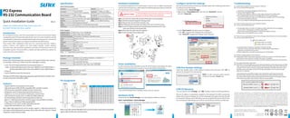
PIN
DCD
RxD
TxD
DTR
GND
DSR
RTS
CTS
RI
DB9M
1
2
3
4
5
6
7
8
9
RJ45
7
6
3
2
4
8
1
5
-
DB25M
8
3
2
20
7
6
4
5
22
Pin Header
1
3
5
7
9
2
4
6
8
User can read the COM
“IO Range”
and
“IRQ”
located in system by selecting COM port.
IRQ and I/O address is automatically assigned by the mainboard PCIe BIOS automatically
(before COM card driver installing). User can NOT assign legacy ISA address (3F8, 3E8, 2F8, 2E8)
for the specific COM port. But for IRQ setting, user can set specific IRQ value for this PCIe bus
slot via mainboard’s BIOS settings (not via driver). But all COM ports will share one IRQ value.
COM I/O Resource
Configure Serial Port Settings
After the board and serial port drivers are installed, please refer to following instructions
to configure Serial COM settings.
1. Please launch the
“Device Manager”
.
2. Right click the
“Ports(COM & LPT)”
item from the
“Serial Port”
sub-tree
and click
“Properties”
.
3. On the
“Port Control”
tab, select a port to configure.
* Click
“OK”
to approve the settings for the selected port.
* Click
“Set to All”
to approve the settings for all COM ports.
Under Port Number, select a COM number to assign to the serial port. Click“OK”to
approve the settings for the selected port.
NOTE: In order to prevent system resource
conflict, do not select
“in use”
port.
COM Port Number Settings
COM Port Number: COM3
COM9 (in use)
COM10 (in use)
COM11
COM12
Hardware Verify
Please launch the
“Device Manager”
to verify hardware installation correctly.
* The number of COM ports will depend on what products you bought.
Troubleshooting
SUNIX COM Port (COM3)
Ports (COM & LPT)
SUNIX COM Port (COM4)
Q 1. System fails to find the PCIe serial board or COM port.
Ans: It may cause by following issue:
a.The board is not properly plugged into the PCIe slot.
b.Please clean the golden finger.
c.The PCIe slot is defective. Please try other slots until you find one that works.
d.The mainboard does not have an available IRQ for the PCIe serial board.
Enter the PC’s BIOS and make sure an IRQ setting is available in the PCI/PnP settings.
e.The board itself might be defective.
You can try another mainboard testing this board working or not.
Q 2. There is a blue screen when I entry operation system.
Ans: It may cause by following issue:
a.The possible reason is an IRQ or I/O address conflict with other PCIe bus adapters,
such as LAN or serial boards, or with the system BIOS.
Refer to the corresponding problem in the previous FAQ for solutions.
b.Please check driver update from your vendor.
Q 3. There are some exclamation marks in device manager and serial ports can not work properly.
Ans: It may cause by following issue:
a.It caused by the wrong driver installing or hardware settings.
Please turn off your computer firstly and re-install hardware and software,
especially re-install the correct driver.
b.Please update driver manually by specifying driver INF file folder.
Q 4. Should I enable auto flow control features?
Ans: Enable Auto CTS/RTS Flow Control means the CTS/RTS flow control is controlled by hardware
automatically. System will be more stable if the function is enabled.
Please make sure your serial device and cable wiring before enabling the hardware flow control function.
Q 5. How large FIFO length I should set?
Ans: FIFO (First-in-First-out) buffers are used to reduce the frequency of interrupt processes for UART
chips. The size of the buffer will determine the number of times the cards need to interrupt the
computer’s CPU in order to process a string of data. With larger FIFO buffer size; there is more
data flow and less interruption to the CPU, therefore allowing the CPU to be free to handle
other more crucial tasks.
Set the Receive/Transmit Buffer to higher value will get faster performance because the
interrupts will be reduced, but the time for interrupt service routine will become shorter.
The receive buffer overflow will be easily happened if the CPU speed is not enough to handle.
If the system is not stable, select the lower value to correct problems.
E-mail for technical support: info@sunix.com
Website for product information: www.sunix.com
Tel: +886-2-8913-1987
Fax: +886-2-8913-1986
Made in China
771-QPCIE2323-S01
Enable 128 Byte FIFO buffers
Receive Buffer: Low (1) High (112)
Transmit Buffer: Low (1) High (128)
1 8
1
5
6
9
1
2
9
10
1
DB25M DB9M RJ45
Pin Header
(Pitch 2.0mm)
13
14
25
Note: 8-port RS-232/422/485 Multi-Port communication board does not build RI
signal under the RS-232 communication.
To avoid damaging to the computer, make sure to remove
any power connection before card installation.
SAFETY FIRST
Step 1: Turn your PC’s power off, and shut off the power to any peripheral.
Step 2: Remove the power plug from the plug socket.
Step 3: Remove the cover from the computer case.
Step 4: If fitted. Remove the metal cover plate on the rear of a free PCI-E slot.
Step 5: Insert PCI Express Serial Communication Board into the free PCI-E slot
and screw it firmly on the bracket side.
Step 6: Place the cover back onto the computer.
Step 7: Insert the plug into the plug socket.
The hardware installation of PCIe Serial board is easy to carry out. Before inserting the
card into the PCIe Express bus, please follow the detailed steps given below to install the
PCIe Serial board in your computer.