SlideShare une entreprise Scribd logo
1  sur  116
Télécharger pour lire hors ligne
BEARING CAPACITY
Submitted to: Dr. Sanjeev Naval
Submitted by: Abhishek Sharma 661/15D.A.V.I.E.T
1
1.INTRODUCTION
The subject of bearing capacity is perhaps the most important
of all the aspects of geotechnical engineering.
Loads from buildings are transmitted to the foundation by
columns, by load bearing walls or by such other load-bearing
components of the structures.
Sometimes the material on which the foundation rests is
ledge, very hard soil or bed-rock, which is known to be much
stronger than is necessary to transmit the loads from the structure.
2
ABHISHEK SHARMA 661
Such a ledge, or rock, or other stiff material may
not be available at reasonable depth and it becomes
invariably necessary to allow the structure to bear directly
on soil, which will furnish a satisfactory foundation, if the
bearing members are properly designed.
It is here that the subject of bearing capacity
assumes significance.
3
ABHISHEK SHARMA 661
2.SOME BASIC DEFINITIONS
Foundation: The lowest part of a structure which is in contact with
soil and transmits loads to it.
Footing is a foundation consisting of a small slab for transmitting
the structural load to the underlying soil. Footings can be
individual slabs supporting single columns or combined to
support two or more columns or be a long strip of concrete
slab. width B to length L ratio is small, i.e., it approaches zero)
supporting a load-bearing wall, or a mat.
Foundation soil or bed: The soil or bed to which loads are
transmitted from the base of the structure.
4
ABHISHEK SHARMA 661
Bearing capacity (q): The load-carrying capacity of foundation
soil or rock which enables it to bear and transmit loads from a
structure.
ULTIMATE bearing capacity (qult): Maximum pressure which a
foundation can withstand without the occurrence of shear failure
of the foundation.
Gross Ultimate bearing capacity: The bearing capacity inclusive
of the pressure exerted by the weight of the soil standing on
the foundation, or the ‘surcharge’ pressure, as it is sometimes
called.
Net Ultimate bearing capacity (qnu): Gross bearing capacity
minus the original overburden pressure or surcharge pressure at
the foundation level; obviously, this will be the same as the
gross capacity when the depth of foundation is zero, i.e., the
structure is founded at ground level. 5ABHISHEK SHARMA 661
Safe bearing capacity (qs ): Ultimate bearing capacity divided by
the factor of safety. The factor of safety in foundation may
range from 2 to 5,
The factor of safety should be applied to the net
ultimate bearing capacity
the surcharge pressure due to depth of the foundation
should then be added to get the safe bearing capacity.
It is thus the maximum intensity of loading which can
be transmitted to the soil without the risk of shear failure,
irrespective of the settlement that may occur.
6
ABHISHEK SHARMA 661
GROSS SAFE BEARING CAPACITY: It is the maximum gross
intensity (inclusive of overburden pressure) of loading at the base
of the foundation that the soil can support before failing in shear
NET SAFE BEARING CAPACITY (qns ): It is the maximum net
intensity (exclusive of overburden pressure) of loading at the
base of the foundation that the soil can support without the risk
of shear failure.
ALLOWABLE BEARING PRESSURE (qa ): The maximum allowable
net loading intensity on the soil at which the soil never fails in
shear and doesn’t pose any excessive settlement or can be say
that the settlements are under permissible limits.
7
ABHISHEK SHARMA 661
Ultimate limit state defines a limiting stress or force
that should not be exceeded by any conceivable or
anticipated loading during the design life of a
foundation or any geotechnical system.
Serviceability limit state defines a limiting
deformation or settlement of a foundation, which, if
exceeded, will impair the function of the structure
that it supports.
8
ABHISHEK SHARMA 661
9
AS PER IS 6403 : 1981
Net Loading Intensity: The net loading intensity on the foundation is
the gross intensity of loading minus the weight of displaced soil above
the foundation base.
Ultimate Bearing Capacity : The intensity of loading at the base or
the foundation which would cause shear failure of the soil support.
Safe Bearing capacity : Maximum intensity of loading that the
foundation will safely carry without the risk of shear failure of soil
irrespective of any settlement that may occur.
Safe Bearing Pressure or Net Soil Pressure : The Intensity of loading
that will cause a permissible settlement or specified settlement of the
structure.
ABHISHEK SHARMA 661
10
Allowable Bearing Capacity : The net intensity of loading which the
foundation will carry without undergoing settlement in excess or the
permissible value for the structure under consideration but not
exceeding net safebearing capacity
ABHISHEK SHARMA 661
3. TYPES OF FAILURE IN SOIL
11
Experimental investigations have indicated that
foundations on dense sand with relative density greater
than 70 percent fail suddenly with pronounced peak
resistance when the settlement reaches about 7 percent of
the foundation width. The failure is accompanied by the
appearance of failure surfaces and by considerable
bulging of a sheared mass of sand as shown in Fig.
This type of failure is designated as general shear failure
by Terzaghi (1943)
ABHISHEK SHARMA 661
12
ABHISHEK SHARMA 661
13
Foundations on sand of relative density lying between 35 and 70
percent do not show a sudden failure. As the settlement exceeds
about 8 percent of the foundation width, bulging of sand starts at
the surface. At settlements of about 15 percent of foundation
width, a visible boundary of sheared zones at the surface appears.
However, the peak of base resistance may never be reached. This
type of failure is termed local shear failure, Fig.
ABHISHEK SHARMA 661
14
Foundations on relatively loose sand with relative
density less than 35 percent penetrate into the soil without
any bulging of the sand surface.
The base resistance gradually increases as
settlement progresses. The rate of settlement, however,
increases and reaches a maximum at a settlement of about
15 to 20 percent of the foundation width.
Sudden jerks or shears can be observed as soon as
the settlement reaches about 6 to 8 percent of the
foundation width.
The failure surface, which is vertical or slightly
inclined and follows the perimeter of the base, never
reaches the sand surface. This type of failure is designated
as punching shear failure by Vesic (1963)
ABHISHEK SHARMA 661
15
ABHISHEK SHARMA 661
16
The approximate limits of types of failure to be affected as relative
depth DF / B and relative density of sand, Dr, vary are shown in Fig.
(Vesic, 1963). General shear failure occur when φ is more than or
equal to 380. Local Shear Failure occur when φ is than or equal to 280
4.CRITERIA FOR THE DETERMINATION OF
BEARING CAPACITY
1. LOCATION AND DEPTH:
A foundation must be properly located and
founded at such a depth that its performance does
not affected by factors such as lateral expulsion of
soil from beneath the foundation, seasonal volume
changes, presence of adjoining structures etc.
17
ABHISHEK SHARMA 661
2. Shear failure of the foundation or bearing capacity failure, as
it is sometimes called, shall not occur. (This is associated with
plastic flow of the soil material underneath the foundation,
and lateral expulsion of the soil from underneath the footing of
the foundation); and,
3. The probable settlements, differential as well as total, of the
foundation must be limited to safe, tolerable or acceptable
magnitudes. In other words, the anticipated settlement under
the applied pressure on the foundation should not be
detrimental to the stability of the structure.
Last two criteria are known as the shear strength criterion,
and settlement criterion, respectively. The design value of
the safe bearing capacity, obviously, would be the smaller of
the two values, obtained from these two criteria.18
ABHISHEK SHARMA 661
5.FACTORS AFFECTING BEARING
CAPACITY
(i) Nature of soil and its physical and engineering properties;
(ii) Nature of the foundation and other details such as the size,
shape, depth below the ground surface and rigidity of the
structure;
(iii) Total and differential settlements that the structure can
withstand without functional failure;
(iv) Location of the ground water table relative to the level of
the foundation; and
(v) Initial stresses, if any.
19
ABHISHEK SHARMA 661
6.METHODS OF DETERMINING BEARING
CAPACITY
(i) Bearing capacity tables in various building codes
(ii) Analytical methods
(iii) Plate bearing tests
(iv) Penetration tests
(v) Model tests and prototype tests
(vi) Laboratory tests
20
ABHISHEK SHARMA 661
ACCORDING TO OUR SYLLABUS FOLLOWING
METHODS ARE PRESCRIBED IN DETAIL ONE BY ONE.
1. The theory of elasticity—Schleicher’s method.
2. The classical earth pressure theory—Rankine’s method, Pauker’s
method and Bell’s method.
3. The theory of plasticity—Fellenius’ method, Prandtl’s method, Terzaghi’s
method,
Meyerhof’s method, Skempton’s method, Hansen’s method and Balla’s
method.
PLATE LOAD TEST AND PENETRATION TEST
ANALYTIC APPROACH
21
ABHISHEK SHARMA 661
7. RANKINE METHOD
This method, based
on Rankine’s earth pressure
theory, is too approximate and
conservative for practical use.
22
WILLIAM RANKINE (1820–1872)
ABHISHEK SHARMA 661
23
Rankine uses the relationship between principal
stresses at limiting equilibrium conditions of soil elements,
one located just beneath the footing and the other just
outside it as shown in Fig.
ABHISHEK SHARMA 661
In element I, just beneath the footing, at the base level of the
foundation, the applied pressure qult is the major principal
stress; under its influence, the soil adjacent to the element
tends get pushed out, creating active conditions.
The active pressure is σ on the vertical
faces to the element.
From the relationship between the
principal stresses at limiting equilibrium
relating to the active state, we have:
……..EQ.1
24
ABHISHEK SHARMA 661
In element II, just outside the footing, at the base level of the
foundation, the tendency of the soil adjacent to the element
is to compress, creating passive conditions. The pressure σ
on the vertical faces of the element will thus be the passive
resistance.
This will thus be the major principal stress
and the corresponding minor principal stress
is q(= γ.Df)
……..EQ.2
25
ABHISHEK SHARMA 661
FROM EQ.1 AND EQ.2
……..EQ.3
This gives the bearing capacity of the footing. It does not appear to
take into account the size of the footing.
to give Df , which is termed the minimum depth required for a
foundation:
……..EQ.4
It does not appear to take into account the size of the
footing26
ABHISHEK SHARMA 661
An alternative approach based on Rankine’s earth pressure
theory which takes into account the size b of the footing is
as follows:
It is assumed that rupture in the soil takes place along CBD
and CFG symmetrically. The failure zones are made of two
wedges as shown. It is sufficient to consider the equilibrium
of one half.
27
ABHISHEK SHARMA 661
Wedge I is Rankine’s active wedge, pushed downwards by qult on
CA; consequently the vertical face AB will be pushed outward.
Wedge II is Rankine’s passive wedge. The pressure P on face AB
of wedge I will be the same as that which acts on face AB of
wedge II; consequently, the soil wedge II is pushed up. The
surcharge, q = γ.Df, due to the depth of footing resists this.
……..EQ.528
ABHISHEK SHARMA 661 ABHISHEK SHARMA 661
from Rankine’s theory for the case with surcharge.
From Wedge I, similarly,
…..EQ.6
Equating the two values of P from EQ.5.5 and EQ.6, we get
…..EQ.7
This is written as
…..EQ.8
…..EQ.9
…..EQ.10
Both are known as BEARING CAPACITY FACTORS
29
ABHISHEK SHARMA 661
8.Prandtl’s Method
30
Prandtl analyzed the
plastic failure in metals
when punched by hard
metal punchers (Prandtl,
1920). This analysis has
been adapted to soil
when loaded to shear
failure by a relatively
rigid foundation (Prandtl,
1921).
Ludwig Prandtl
4 February 1875 - 15 August 1953
ABHISHEK SHARMA 661
31
The assumptions in Prandtl’s theory are:
(i) The soil is homogeneous, isotropic and weightless.
(ii) The Mohr-Coulomb equation for failure envelope τ = c + σ tan υ
is valid for the soil,
(iii) Wedges I and III act as rigid bodies. The zones in Sectors II
deform plastically. In the plastic zones all radius vectors or planes
through A and B are failure planes and the curved boundary is a
logarithmic spiral.
(iv) Wedge I is elastically pushed down, tending to push zones III
upward and outward, which is resisted by the passive resistance of
soil in these zones.
(v) The stress in the elastic zone I is transmitted hydrostatically in all
directions.
ABHISHEK SHARMA 661
32
qult = c cot φ (Nφ . eπ tan φ – 1)
This is Prandtl’s expression for ultimate bearing capacity of a c – υ soil.
…..EQ.11
33
purely cohesive soils, φ = 0
qult = (π + 2)c = 5.14c
Discussion of Prandtl’s Theory
(i) Prandtl’s theory is based on an assumed compound rupture surface,
consisting of an arc of a logarithmic spiral and tangents to the spiral.
(ii) It is developed for a smooth and long strip footing, resting on the
ground surface.
(iii) Prandtl’s compound rupture surface corresponds fairly well with the
mode of failure along curvilinear rupture surfaces observed from
experiments.
(iv) Prandtl’s expression, as originally derived, does not include the
size of the footing.
…..EQ.12
ABHISHEK SHARMA 661
9. TERZAGHI METHOD (1943).
Terzaghi’s method is, in fact,
an extension and improved
modification of Pandtl’s
34
ABHISHEK SHARMA 661
Karl von Terzaghi
2 October 1883 -- 25 October 1963
ABHISHEK SHARMA 661
35
The soil is a semi-infinite, homogeneous, isotropic, weightless,
rigid–plastic material.
ASSUMPTIONS:
The embedment depth is not greater than the width of the
footing (Df < B).
General shear failure occurs & The base of the footing is
rough.
The soil above the footing base can be replaced by a
surcharge stress. This, in effect, means that the shearing
resistance of the soil located above the base is neglected.
ABHISHEK SHARMA 661
The zone of plastic equilibrium, CDEFG, can be subdivided into I a
wedge-shaped zone located beneath the loaded strip, in which the
major principal stresses are vertical,
II two zones of radial shear, BCD and ACG, emanating from the outer
edges of the loaded strip, with their boundaries making angles (45° –
φ/2) and φ with the horizontal, and
III two passive Rankine zones, AGF and BDE, with their boundaries
making angles (45° – υ/2) with the horizontal.36
ABHISHEK SHARMA 661
The adhesion force Ca on the faces
AC and BC is given by:
…..EQ.13
Considering a unit length of the footing and the equilibrium of wedge
ABC, the vertical components of all forces must sum up to zero.
…..EQ.14
…..EQ.15
…..EQ.16
The weight of the soil in the wedge is given by
37
ABHISHEK SHARMA 661
For the simpler case of Df = 0 and c = 0, q = 0—that is, if the base
of the footing rests on the horizontal surface of a mass of
cohesionless sand, we have:
…..EQ.17
Here Kpγ is the coefficient of passive earth pressure for c = 0,
α = 180° – υ, and δ = υ ; that is, it is the value purely due to the
weight of the soil.
38
ABHISHEK SHARMA 661
…..EQ.18
…..EQ.19
…..EQ.20
Substituting EQ.15 in EQ.14
The value of Kpγ is obtained by means of the spiral or the friction
circle method.
Nγ is called the ‘‘bearing-capacity factor’’ expressing the effect of the
weight of the soil wedge, ABC, of a cohesionless soil.
39
ABHISHEK SHARMA 661
For the calculation of the bearing capacity of a cohesive soil, the
computation of Pp involves a considerable amount of labour.
Terzaghi, therefore, advocated a simplified approach, which is
based on the equation
…..EQ.21
where Ppn = normal component of the passive earth pressure on
a plane contact face with a height H,
α = slope angle of the contact face, and
Kpc, Kpq, and Kpγ = coefficients whose values are indpendent of
H and γ. In the present case,
40
ABHISHEK SHARMA 661
Also the total passive earth pressure Pp on the contact face is
equal to
…..EQ.22
where (cKpc + qKpq) = Ppn is the normal component of the passive
earth pressure comprehending the effect of cohesion and surcharge.
Combining this equation with Eq. 14, we have
…..EQ.23
41
ABHISHEK SHARMA 661
If the soil wedge, ABC, is assumed weightless (γ = 0) (Prandtl, 1920),
Eq. (21) takes the form
…..EQ.24
The factors Nc and Nq are pure numbers whose values depend only
on the value φ in Coulomb’s equation.
On the other hand, if c = 0 and q = 0, γ being greater than zero,
the bearing capacity is given by Eqs. 17 and 18:
42
ABHISHEK SHARMA 661
If the values c, Df, and γ are greater than zero,
…..EQ.25
This is called ‘‘Terzaghi’s general
bearing capacity formula’’.
The coefficients Nc, Nq, and Nγ are called ‘‘bearing capacity
factors’’ for shallow continuous footings.
43
ABHISHEK SHARMA 661
The problem of Nc and Nq has been rigorously solved by
means of Airy’s stress function (Prandtl 1920, Reissner,
1924), for the condition γ = 0:
…..EQ.26
…..EQ.27
…..EQ.28
The values Nc and Nq depend
only on the value of υ.
44
ABHISHEK SHARMA 661
Bearing capacity of a strip footing with a rough base on
the ground surface is given by,
qult = 5.7c …..EQ.29
For strip footing at a depth Df in a purely cohesive soil
qult = 5.7c + γDf. …..EQ.30
Equation 23, along with the bearing capacity factors Nc, Nq and Nγ
are valid for ‘general shear failure’.
For ‘local shear failure’, as given by Terzaghi :
c′ = (2/3)c
tan φ′ = (2/3) tan φ
…..EQ.31
…..EQ.32
45
ABHISHEK SHARMA 661
for local shear failure,
…..EQ.33
Terzaghi’s bearing capacity factors are plotted in Fig.
46
ABHISHEK SHARMA 661
As a general guideline, if failure occurs at less than
5% strain and if density index is greater than 70%,
general shear failure may be assumed,
if the strain at failure is 10% to 20% and if the
density index is less than 20%, local shear failure may be
assumed, and,
for intermediate situations punching shear, linear
interpolation of the factors may be employed.
QUICK NOTE
47
ABHISHEK SHARMA 661
The bearing capacity factors of Terzaghi are
tabulated in following Table
48
ABHISHEK SHARMA 661
Bearing capacity of shallow circular and square
footings
Bearing capacity of circular footings has been proposed
by Terzaghi as follows,
qultc = 1.3 cNc + γDf Nq + 0.3 γ d Nγ …..EQ.34
where d = diameter of the circular footing.
The critical load for the footing is given by
…..EQ.35
49
ABHISHEK SHARMA 661
Similarly, the bearing capacity of a square footing of side
b is:
qults = 1.3 cNc + γDfNq + 0.4 γb Nγ …..EQ.36
Qults = (b2) . Qults
The critical load for the footing is given by
For a continuous footing of width b, it is already seen
that,
qult = cNc + γDf Nq + 0.5 γ b Nγ
…..EQ.37
…..EQ.38
50
ABHISHEK SHARMA 661
Thus, the bearing capacity of a circular footing of diameter
equal to the width of a continuous footing is 1.3 times
that of the continuous footing, or at least nearly so, if the
footings are founded in a purely cohesive soil (φ = 0);
the bearing capacity of a square footing of side
equal to the width of a continuous footing also bears a
similar relation to that of the continuous footing under similar
conditions just cited.
Further, the corresponding ratios are 0.6 and 0.8 in
the case of circular footing and square footing,
respectively, when the footings are founded in a purely
cohesionless soil (c = 0).
QUICK NOTE
51
ABHISHEK SHARMA 661
10. SKEMPTON METHOD (1951)
He found that the factor Nc is a
function of the depth of
foundation and also of its
shape.
52
ABHISHEK SHARMA 661
Alec Skempton
4 June 1914 - 9 August 2001
53
The net ultimate bearing capacity is given by:
qnet ult = c . Nc …..EQ.39
Strip footings:
Nc = 5 (1 + 0.2 Df /b)
with a limiting value of
Nc of 7.5 for Df /b > 2.5.
…..EQ.40
Square or Circular
footings:
Nc = 6(1 + 0.2Df /b)
with a limiting value of
Nc of 9.0 for Df /b >2.5.
(b is the side of square or
diameter of circular footing).
EQ.41 …..
ABHISHEK SHARMA 661
for Df /b ≤ 2.5, for Df /b > 2.5,
b = width of the rectangular footing,
L = length of the rectangular footing.
Nc = 7.5 (1 + 0.2 b/L)
…..EQ.42 & EQ.43
54
ABHISHEK SHARMA 661
For a surface footing of square or circular shape on
purely cohesive soil
Qnet ult = 6c ...(Eq. 44)
as against 7.4c from Terzaghi’s theory.
It must be noted that Terzaghi’s theory is limited to
shallow foundations wherein Df /b ≤ 1,
but
Skempton’s equations do not suffer from such a limitation.
QUICK NOTE
55
ABHISHEK SHARMA 661
11. Brinch Hansen’s Method
56
Brinch Hansen (1961) has proposed the following semi-
empirical equation for the bearing capacity of a footing,
as a generalisation of the Terzaghi equation:
…..EQ.45
Qult = vertical component of the total load
A = effective area of the footing
q = overburden pressure at the foundation level (= γ . Df),
Nq = Nυ . eπ tan υ
Nc = (Nq – 1) cot φ
Nγ = 1.8 (Nq – 1) tan υ
(Nυ = tan2 (45° + υ/2), with the usual notation.)
ABHISHEK SHARMA 661
57
S = shape factors
d = depth factors, and
i = inclination factors.
Brinch Hansen’s shape factors
Brinch Hansen’s depth factors
ABHISHEK SHARMA 661
58
Brinch Hansen’s inclination factors
Revised values of inclination factors:
…..EQ.46
…..EQ.47
…..EQ.48But, for φ = 0°,
ABHISHEK SHARMA 661
12. Balla’s Method
59
Balla has proposed a theory for the bearing capacity of continuous
footings (Balla 1962).
The theory appears to give values which are in good agreement
with field test results for footings founded in cohesionless soils.
The form of the bearing capacity equation is the same as that of
Terzaghi:
…..EQ.49
ABHISHEK SHARMA 661
60
But the equations for the bearing capacity factors are
cumbersome to solve without the aid of a digital computer. Therefore,
it is generally recommended that Balla’s charts be used for the
determination of these factors.
ABHISHEK SHARMA 661
61
The limitations are that it should be used when Df / b ≤ 1.5
and that it is applicable to continuous footings only.
ABHISHEK SHARMA 661
13. Meyerhof’s Method
62
The important difference between Terzaghi’s and Meyerhof’s
approaches is that the latter considers the shearing resistance of the
soil above the base of the foundation, while the former ignores it.
Thus, Meyerhof allows the failure zones to extend up to the ground
surface (Meyerhof, 1951).
ABHISHEK SHARMA 661
63
Zone I ABC ... elastic
Zone II BCD ... radial shear
Zone III BDEF ... mixed shear
wherein Nc, Nq and Nγ are ‘‘Meyerhof’s bearing capacity factors’’,
which depend not only on υ, but also on the depth and shape of the
foundation and roughness of the base.
Meyerhof’s factors are more difficult to obtain than Terzaghi’s, and
have been presented in the form of charts by Meyerhof.
For strip footings: Nc = 5.5(1 + 0.25 Df/b)
with a limiting value of 8.25 for Nc for Df /b > 2.5.
…..EQ.50
For square or circular footings: Nc = 6.2 (1 + 0.32 Df /b)
with a limiting value of 9.0 for Nc for Df /b > 2.5.
(b is the side of a square or diameter of circular footing).
ABHISHEK SHARMA 661
14. Vesic's Bearing Capacity Theory
64
Vesic(1973) confirmed that the basic nature of failure surfaces in
soil as suggested by Terzaghi as incorrect.
However, the angle which the inclined surfaces make with the
horizontal was found to be closer to 45 + υ/2 instead of υ . The values
of the bearing capacity factors , , for a given angle of shearing
resistance change if above modification is incorporated in the analysis as
under
…..EQ.51
…..EQ.52
…..EQ.53
ABHISHEK SHARMA 661
65
eqns(51)was proposed by Prandtl(1921),and eqn(52) was given by
Reissner (1924). Caquot and Keisner (1953) and Vesic (1973) gave
eqn (53)
…..EQ.54
ABHISHEK SHARMA 661
66
Depth factor
Inclination factor
ABHISHEK SHARMA 661
15. IS 6403:1981 METHOD
67
…..EQ.55
If the water table is at or below a depth of Df +B,
measured from the ground surface, w’=1. If the water
table rises to the base of the footing or above, w’=0.5. If
the water table lies in between then the value is obtained
by linear interpolation. The shape factors given by
Hansen and inclination factors as given by Vesic are
used.
ABHISHEK SHARMA 661
68
For cohesive soils:
Nc = 5.14
ABHISHEK SHARMA 661
16. EFFECT OF WATER TABLE ON
BEARING CAPACITY
Water in soil is known to affect its unit weight and
also the shear parameters c and φ.
When the soil is submerged under water, the
effective unit weight γ′ is to be used in the computation
of bearing capacity.
NOTE:
Effective unit weight γ′ is roughly half the saturated
unit weight; consequently there will be about 50%
reduction in the value of the corresponding term in the
bearing capacity formula.
69
ABHISHEK SHARMA 661
• If the water table is at the level of the base of the
footing, γ′ is to be used for γ in the third term, a reduction
factor of 0.5 is to be applied to the third term.
• For any location of the water table intermediate
between the base of the footing and a depth equal to
the width of the footing below its base, a suitable
linear interpolation of the necessary reduction is
suggested.
• If the water table is above the base of the
footing, the reduction factor for the third term is
obviously limited to the maximum of 0.5.70
ABHISHEK SHARMA 661
• The maximum reduction of 0.5 is indicated for the
second term when the water table is at the ground level
itself (or above it), since γ′ is to be used for γ in the
second term.
• While no reduction in the second term is
required when the water table is at or below the base
of the footing,
• In the case of purely cohesive soils, since φ ≈ 0°,
Nq = 1 and Nγ = 0,
• Net ultimate bearing capacity is given by c . Nc,
which is virtually unaffected by the water table, if it is
below the base of the footing.
71
ABHISHEK SHARMA 661
• If the water table is at the ground level, only the
gross bearing capacity is reduced by 50% of the
surcharge term γ.Df (Nq = 1), while the net value is again
only c . Nc.
• In the case of purely cohesionless soils, since
c = 0, and φ > 0, and Nq and Nγ are significantly high,
For locations of ground water table within a depth of the
width of the foundation below the base and the ground
level, the equation for the ultimate bearing capacity may
be modified as follows:
...(Eq. 56)
*appropriate multiplying factor should be used for isolated footings.
**Appropriate shape factor.
72
ABHISHEK SHARMA 661
c′ = effective cohesion
Nc, Nq, and Nγ = bearing capacity factors based on φ′
Rq and Rγ = reduction factors for the terms involving Nq and Nγ owing to
the effect of water table.
Rq and Rγ may be obtained as follows, from Fig.
zq = 0...Rq = 0.5 zγ = 0...Rγ = 0.5
zq = Df...Rq = 1.0 zγ = b...Rγ = 1.0
73
ABHISHEK SHARMA 661
...(Eq. 57)
...(Eq. 58)
Note.
• For zq > Df (the water table is below the base of
the footing), Rq is limited to 1.0.
• For 0 ≤ zq ≤ Df (the water table is above the base
of the footing), Rγ is limited to 0.5.
• for zq > (Df + b) or zγ > b, Rq as well as Rγ are
limited to 1.0.
• For zq = 0, Rq as well as Rγ are limited to 0.5.
74
ABHISHEK SHARMA 661
17. FOUNDATION SETTLEMENTS
Settlement total settlement and differential settlement of foundations
and consequently of the structures above the foundations.
Source of Settlement
(i) Elastic compression of the foundation and the underlying soil, giving
rise to what is known as ‘immediate’, ‘contact’, ‘initial’, or ‘distortion’
settlement,
(ii) Plastic compression of the underlying soil, giving rise to
consolidation, settlement of fine grained soils, both primary and
secondary,
(iii) Ground water lowering, especially repeated lowering and raising
of ground water level in loose granular soils and drainage without
adequate filter protection,
75
ABHISHEK SHARMA 661
(iv) Vibration due to pile driving, blasting and oscillating
machinery in granular soils,
(v) Seasonal swelling and shrinkage of expansive clays,
(vi) Surface erosion, creep or landslides in earth slopes,
(vii) Miscellaneous sources such as adjacent excavation,
mining subsidence and underground erosion.
The settlements from the first two sources alone may
be predicted with a fair degree of confidence.
76
ABHISHEK SHARMA 661
The total settlement may be considered to consist of the following
contributions:
(a) Initial settlement or elastic compression.
(b) Consolidation settlement or primary compression.
(c) Secondary settlement or secondary compression
Initial Settlement or Elastic Compression
This is also referred to as the ‘distortion settlement’ or ‘contact
settlement’ and is usually taken to occur immediately on application
of the foundation load.
Such immediate settlement in the case of partially saturated
soils is primarily due to the expulsion of gases and to the elastic
compression and rearrangement of particles.
In the case of saturated soils immediate settlement is
considered to be the result of vertical soil compression
77
ABHISHEK SHARMA 661
Immediate Settlement in Cohesionless Soils
• Standard Penetration Test (De Beer and Martens, 1957).
This method has been developed for use with the Dutch Cone
Penetrometer but can be adapted for the standard penetration test.
The immediate settlement, Si, is given by:
...(Eq. 58)
H = thickness of the layer getting compressed,
σ0 = effective overburden pressure at the centre of the layer before
any excavation or application of load,
Δσ = vertical stress increment at the centre of the layer,
and Cs = compressibility constant, given by:
...(Eq. 59)
Cr being the static cone resistance (in kN/m2), and
σ0 being the effective overburden pressure at the point tested.
78
ABHISHEK SHARMA 661
The value of Cr obtained from the Dutch Cone penetration test must be
correlated to the recorded number of blows, N, obtained from the
standard penetration test.
According to Meigh and Nixon (1961), Cr ranged from 430N (kN/m2) to
1930N (kN/m2). However, Cr is more commonly taken as 400 N (kN/m2)
as proposed by Meyerhof (1956).
79
ABHISHEK SHARMA 661
The use of charts: The actual number of blows, N, from the standard
penetration test has to be corrected, under certain circumstances to
obtain N′, the corrected value.
Thornburn (1963) has given a set of curves to obtain N′ from N.
He also extended the graphical relationship given by Terzaghi
and Peck (1948) between the settlement of a 305 mm square plate
under a given pressure and the N′-value of the soil immediately
beneath it, as shown in Fig.
For determining the settlement, Sf, of a square foundation on
a deep layer of cohesionless soil by using Terzaghi and Peck’s
formula:
...(Eq. 60)
Sp = Settlement of a 305 mm-square plate, obtained from the chart and,
B = Width of foundation (metres)80
ABHISHEK SHARMA 661
The chart is applicable for deep layers only, that is, for layers of
thickness not less than 4B below the foundation.
For rectangular foundations, a shape factor should presumably be
used. It is as follows:
Settlement of a rectangular foundation of width B = Settlement
of square foundation of size B × shape factor.
81
ABHISHEK SHARMA 661
Immediate Settlement in Cohesive Soils
The immediate settlement of a flexible foundation, according to
Terzaghi (1943), is given by:
...(Eq. 61)
Si = immediate settlement at a corner of a rectangular flexible
foundation of size L × B,
B = Width of the foundation,
q = Uniform pressure on the foundation,
Es = Modulus of elasticity of the soil beneath the foundation,
ν = Poisson’s ratio of the soil, and
It = Influence Value, which is dependent on L/B
82
ABHISHEK SHARMA 661
Si, for a rectangular foundation on the surface of a semi-elastic
medium is given by:
...(Eq. 62)
B = width of the rectangular foundation of size L × B,
q = uniform intensity of pressure,
Es = modulus of elasticity of the soil beneath the foundation,
ν = Poisson’s ratio of the soil, and
Is = influence factor which depends upon L/B.
Skempton (1951) gives the following values of Is :
83
ABHISHEK SHARMA 661
Immediate Settlement of a Thin Clay Layer
For cases when the thickness of the layer is less than 4B, Steinbrenner
(1934) prepared coefficients.
The immediate settlement at the corners of a rectangular foundation on
an infinite layer is given by:
...(Eq. 63)
84
ABHISHEK SHARMA 661
85
ABHISHEK SHARMA 661
Permissible Settlements
There are two main ill-effects of differential settlements:
(i) the architectural effect (cracking of plaster, for example) and
(ii) the structural effect (redistribution of moments and shears, for
example, which may ultimately lead to failure).
Terzaghi and Peck (1948) specify a permissible differential
settlement of 20 mm between adjacent columns and recommend that
foundations on sand be designed for a total settlement of 25 mm.
Skempton and MacDonald (1956) specify that the angular rotation
or distortion between adjacent columns in clay should not exceed
1/300, although the total settlement may go up to 100 mm
Sowers (1957) recommends, in his discussion of the paper by Polshin
and Pokar (1957) a maximum differential settlement of 1/500 for
brick buildings and 1/5000 for foundations of turbogenerators.
86
ABHISHEK SHARMA 661
Bozozuk (1962) summarised his investigations in Ottawa as
follows:
(IS: 1904-1961) recommends a permissible total settlement of 65 mm
for isolated foundations on clay, 40 mm for isolated foundations on
sand, 65 to 100 mm for rafts on clay and 40 to 65 mm for rafts on
sand.
The permissible differential settlement is 40 mm for foundations on
clay and 25 mm for foundations on sand. The angular distortion in the
case of large framed structures must not exceed 1/500 normally and
1/1000 if all kinds of minor damage also are to be prevented.87
ABHISHEK SHARMA 661
Remedial Measures Against Harmful Settlements
1. Removal of soft soil strata, consistent with economy.
2. The use of properly designed and constructed pile foundations
3. Provision for lateral restraint against lateral expulsion of soil mass
from underneath the footing of a foundation.
4. Building slowly on cohesive soils to avoid lateral expansion of a soil
mass and to give time for the pore water to be expelled by the
surcharge load.
5. Reduction of contact pressure on the soil; more appropriately,
proper adjustment between pressure, shape and size of the foundation
in order to attain uniform settlements underneath the structure.
6. Preconsolidation of a building site long enough for the expected
load, depending upon the tolerable settlements;
88
ABHISHEK SHARMA 661
18. CONTACT PRESSURE
‘Contact pressure’ is the actual pressure transmitted from the foundation
to the soil.
A uniformly loaded foundation will not necessarily transmit a uniform
contact pressure to the soil. This is possible only if the foundation is
perfectly ‘flexible’;
89
ABHISHEK SHARMA 661
19. PLATE LOAD TEST
The test essentially consists in loading a rigid plate at the
foundation level, increasing the load in arbitrary increments, and
determining the settlements corresponding to each load after the
settlement has nearly ceased each time a load increment is applied.
The nature of the load applied may be gravity loading or dead
weights on an improvised platform or reaction loading by using a
hydraulic jack. The reaction of the jack load is taken by a cross beam or
a steel truss anchored suitably at both ends.
Test plates are usually square or circular, the size ranging from
300 to 750 mm (side or diameter); the minimum thickness recommended is
25 mm for providing sufficient rigidity.
Jack-loading is superior in terms of accuracy and uniformity of
loading. Settlement of the test plate is measured by means of at least two
or three dial gauges with a least count of 0.02 mm.
90
ABHISHEK SHARMA 661
91
ABHISHEK SHARMA 661
The test pit should be at least five times as wide as the test plate and
the bottom of the test plate should correspond to the proposed
foundation level. At the centre of the pit, a small square hole is made
the size being that of the test plate and the depth being such that,
...(Eq. 64)
92
ABHISHEK SHARMA 661
Bigger size plates are preferred in cohesive soils. The test procedure is
given in IS: 1888–1982 (Revised). The procedure, in brief, is as follows:
(i) After excavating the pit of required size and levelling the base, the
test plate is seated over the ground. A little sand may be spread
below the plate for even support. If ground water is encountered, it
should be lowered slightly below the base by means of pumping.
(ii) A seating pressure of 7.0 kN/m2 (70 g/cm2) is applied and
released before actual loading is commenced.
(iii) The first increment of load, say about one-tenth of the anticipated
ultimate bearing capacity, is applied. Settlements are recorded with
the aid of the dial gauges after 1 min., 4 min., 10 min., 20 min., 40
min., and 60 min., and later on at hourly intervals until the rate of
settlement is less than 0.02 mm/hour, or at least for 24 hours.
93
ABHISHEK SHARMA 661
(iv) The test is continued until a load of about 1.5 times the
anticipated ultimate load is applied. According to another school of
thought, a settlement at which failure occurs or at least 2.5 cms
should be reached.
(v) From the results of the test, a plot should be made between
pressure and settlement, which is usually referred to as the ‘‘load-
settlement curve’’, rather loosely. The bearing capacity is
determined from this plot, which is dealt with in the next
subsection.
Load-Settlement Curves
Load-Settlement curves or pressure-settlement curves to be
more precise, are obtained as a result of loading tests either in the
laboratory or in the field, oedometer tests being an example in the
laboratory and plate bearing test, in the field.
94
ABHISHEK SHARMA 661
Curve I is typical of
dense sand or gravel or
stiff clay, wherein general
shear failure occurs.
Curve II is typical of
loose sand or soft clay,
wherein local shear failure
occurs.
Curve III is typical of
many c – φ soils which
exhibit characteristics
intermediate between the
above two.
95
ABHISHEK SHARMA 661
Determination of bearing capacity from plate load test
(Terzaghi and Peck, 1948):
...(Eq. 65)
S = settlement of the proposed foundation (mm),
Sp = settlement of the test plate (mm),
b = size of the proposed foundation (m), and
bp = size of the test plate (m).
This is applicable for sands.
96
ABHISHEK SHARMA 661
The relationship is simpler for clays, since the modulus value
Es, for clays is reasonably constant:
...(Eq. 66)
Sp = Settlement of a test plate of 300 mm square size, and
S = Settlement of a footing of width b.
The method for the determination of the bearing capacity of a footing
of width b should be apparent now. The permissible settlement value,
such as 25 mm, should be substituted in the equation that is applicable
(Eq. 50 to 51) ; and the Sp, the settlement of the plate must be
calculated. From the load-settlement curve, the pressure corresponding
to the computed settlement Sp, is the required value of the ultimate
bearing capacity, qult, for the footing.97
ABHISHEK SHARMA 661
Limitations of Plate Load Tests
(i) Size (plate) effects are very important.
(ii) Consolidation settlements in cohesive soils, which may take
years, cannot be predicted,
(iii) Results from plate load test are not recommended to be
used for the design of strip footings,
(iv) The load test results reflect the characteristics of the soil
located only within a depth of about twice the width of the
plate.
Thus, it may be seen that interpretation and use of the
plate load test results requires great care and judgment,
on the part of the foundation engineer.
98
ABHISHEK SHARMA 661
20. BEARING CAPACITY FROM
PENETRATION TESTS
Terzaghi and Peck have prepared charts for allowable
bearing pressure, based on a standard allowable
settlement, for footings of known widths on sand, whose
N-values are known.
99
ABHISHEK SHARMA 661
Above figures do not apply to gravels or those soils containing a large
percentage of gravels. These charts have been prepared on the
assumption that the water table is at a depth greater than the width of
the footing below the base of the footing. If the water table is located at
the base of the footing, the allowable pressure is taken as half that
obtained from the charts.
100
ABHISHEK SHARMA 661
Charts given by Peck, Hanson and Thornburn (1953) may be used
for the determination of allowable bearing pressure for a specific
allowable settlement of 25 mm or 40 mm,
Fig.1 allowable bearing pressure
for 40mm settlement.
Fig.2 allowable soil pressure101
ABHISHEK SHARMA 661
102
Teng (1969) has proposed the following equation for the graphical
relationship of Terzaghi and Peck for a settlement of 25 mm:
...(Eq. 67)
where qna = net allowable soil pressure in kN/m2 for a settlement
of 25 mm,
N = Standard penetration value corrected for overburden pressure
and other applicable factors,
b = width of footing in metres,
Rγ = correction factor for location of water table, (Eq.56)
and Rd = Depth factor (= 1 + Df /b) ≤ 2.
where Df = depth of footing in metres.
The modified equation of Teng is as follows:
...(Eq. 68)
ABHISHEK SHARMA 661
103
Meyerhof (1956) has proposed slightly different equations for a
settlement of 25 mm, but these yield almost the same results as Teng’s
equation:
...(Eq. 69)
...(Eq. 70)
Modified equation of Meyerhof is as follows:
...(Eq. 71)
...(Eq. 72)
ABHISHEK SHARMA 661
The I.S. code of practice gives Eq. 73 for a settlement of 40 mm; but,
it does not consider the depth effect.
...(Eq. 73)
...(Eq. 73 a)
qna = net allowable soil pressure in kN/m2 for a settlement
of 25 mm,
N = Standard penetration value corrected for overburden
pressure and other applicable factors,
b = width of footing in metres,
Rγ = correction factor for location of water table, (Eq.52)
Rd = Depth factor (= 1 + Df /b) ≤ 2.
Df = depth of footing in metres.
104
ABHISHEK SHARMA 661
105
Teng (1969) also gives the following equations for bearing
capacity of sands based on the criterion of shear failure:
...(Eq. 74)
...(Eq. 75)
N = Standard penetration value, after applying the necessary
corrections,
b = width of continuous footing (side, if square, and diameter, if
circular in metres),
Df = depth of footing in metres, and
Rγ and Rq = correction factors for the position of the ground water
table, defined in Eqs. 52 & 53.
ABHISHEK SHARMA 661
21. BEARING CAPACITY OF CLAYS
106
For pure clays, φ = 0°.
(for square or circular footings, c being the cohesion.)
...(Eq. 76)
ABHISHEK SHARMA 661
QUICK NOTE
Skempton’s equations are preferred for rectangular footings in pure
clay.
Correlation of cohesion and consistency of clays with N-values is not
reliable. Unconfined compression test is recommended for evaluating
cohesion.
Overconsolidated or precompressed clays might show hair cracks and
slickensides. Load tests are recommended in such cases.
Settlements of footings in clays may be calculated or predicted by the
use of Terzaghi’s one-dimensional consolidation.
The bearing capacity of footings in clays is practically unaffected by
the size of the foundation.
107
ABHISHEK SHARMA 661
Example1: Compute the safe bearing capacity of a square footing 1.5
m × 1.5 m, located at a depth of 1 m below the ground level in a soil
of average density 20 kN/m3. φ = 20°, Nc = 17.7, Nq = 7.4, and
Nγ = 5.0. Assume a suitable factor of safety and that the water table is
very deep. Also compute the reduction in safe bearing capacity of the
footing if the water table rises to the ground level.
b = 1.5 m Square footing Df = 1 m
γ = 20 kN/m3 φ = 20° Nc = 17.7, Nq = 7.4, and Nγ = 5.0
Assume c = 0 and η = 3
qult = 1.3 c Nc + 0.4 γ b Nγ + γDf Nq = 0.4 γ b Nγ + γ Df Nq, in this
case.
= 0.4 × 20 × 1.5 × 5.0 + 20 × 1 × 7.4 = 60 + 148 = 208 kN/m2
qnet ult = qult – γ Df = 208 – 20 × 1 = 188 kN/m2
108
ABHISHEK SHARMA 661
If the water table rises to the ground level,
Rγ = 0.5 = Rq
∴ qult = 0.4 γ bNγ . Rγ + γDf Nq . Rq
= 0.4 × 20 × 1.5 × 5.0 × 0.5 + 20 × 1 × 7.4 × 0.5
= 30 + 74 = 104 kN/m2
qnet ult = qult – γ′Df = 104 – 10 × 1 = 94 kN/m2
Percentage reduction in safe bearing capacity
109
ABHISHEK SHARMA 661
Example 2: A plate load test was conducted on a uniform deposit of sand
and the following data were obtained:
(i) Plot the pressure-settlement curve and determine the failure stress.
(ii) A square footing, 2m × 2 m, is to be founded at 1.5 m depth in this
soil. Assuming the factor of safety against shear failure as 3 and the
maximum permissible settlement as 40 mm, determine the allowable
bearing pressure.
(iii) Design of footing for a load of 2,000 kN, if the water table is at
a great depth.
110
ABHISHEK SHARMA 661
(i) The pressure-settlement curve is shown in Fig. The failure point is
obtained as the point corresponding to the intersection of the initial
and final tangents. In this case, the failure stress is 500 kN/m2.
∴ qult = 500 kN/m2
111
ABHISHEK SHARMA 661
(ii) The value of qult here is given by
0.5.γbp Nγ .
bp, the size of test plate = 0.75 m
Assuming γ = 20 kN/m3,
500 = 0.5 × 20 × 0.75 Nγ
∴ Nγ = 500/7.5 ≈ 6.7
φ = 38°
∴ Nq ≈ 50 from Terzaghi’s charts.
For square footing of size 2 m and Df = 1.5 m,
qnet ult = 0.4 γ b Nγ + γDf (Nq – 1)
= 0.4 × 20 × 2 × 67 + 20 × 1.5 × 49 = 2,542 kN/m2
qsafe = 2542/3 ≈ 847 kN/m2 (for failure against shear)
112
ABHISHEK SHARMA 661
Pressure for a settlement of 27 mm for the plate (from Fig. ) = 550
kN/m2. Allowable bearing pressure is the smaller of the values from
the two criteria = 550 kN/m2.
(iii) Design load = 2,000 kN
From Part (ii), it is known that a 2 m square footing can carry a load of
2 × 2 × 550 = 2,200 kN.
Therefore, a 2 m square footing placed at a depth of 1.5 m is
adequate for the design load.
113
ABHISHEK SHARMA 661
114
Example 3 (ESE CE 2017)
In a plate load test on a soil, at a particular magnitude of the
settlement, it was observed that the bearing pressure beneath the footing
is 100 kN/m2 and the perimeter shear is 25 kN/m2. Correspondingly, the
load capacity of a 2m square footing at the same settlement will be
(a) 200 kN (b) 300 kN
(c) 400 kN (d) 600 kN
Sol.
Q = Aσb + P σ s
σ b = Bearing pressure
σ s = Perimeter shear
A = Plate base area
P = Perimeter
Q = Load capacity
Q = 2 × 2 × 100 + 2 × 4 × 25
Q = 600 kN
115
GATE 2018 :The contact pressure and settlement distribution
for a footing are shown in the figure. The figure corresponds to
a
(a) rigid footing on granular soil
(b) flexible footing on granular soil
(c) flexible footing on saturated clay
(d) rigid footing on cohesive soil.
REFRENCES:
C. VENKATARAMAIAH
GEOTECHNICAL ENGINEERING
THIRD EDITION
( NEW AGE INTERNATIONAL (P) LTD. PUBLISHERS)
MUNI BUDHU-
SOIL MECHANICS AND FOUNDATIONS
THIRD EDITION -WILEY (2010)
A.S.R RAO & GOPAL RANJAN-
BASIC AND APPLIED SOIL MECHANICS
(NEW AGE INTERNATIONAL (P) LTD., PUBLISHERS)
116 ABHISHEK SHARMA 661
IS 6401:1981 & IS: 1888–1982

Contenu connexe

Tendances

Unit 1 sheet pile-converted
Unit 1   sheet pile-convertedUnit 1   sheet pile-converted
Unit 1 sheet pile-convertedNigitha rajan
 
Bearing capacity of Soil
Bearing capacity of SoilBearing capacity of Soil
Bearing capacity of SoilPirpasha Ujede
 
Geotechnical Engineering-II [Lec #11: Settlement Computation]
Geotechnical Engineering-II [Lec #11: Settlement Computation]Geotechnical Engineering-II [Lec #11: Settlement Computation]
Geotechnical Engineering-II [Lec #11: Settlement Computation]Muhammad Irfan
 
Geotechnical Engineering-II [Lec #19: General Bearing Capacity Equation]
Geotechnical Engineering-II [Lec #19: General Bearing Capacity Equation]Geotechnical Engineering-II [Lec #19: General Bearing Capacity Equation]
Geotechnical Engineering-II [Lec #19: General Bearing Capacity Equation]Muhammad Irfan
 
Unconfined Compression Test
Unconfined Compression TestUnconfined Compression Test
Unconfined Compression TestLove Sharma
 
Shear strength of soil
Shear strength of soilShear strength of soil
Shear strength of soilAditya Mistry
 
Geotechnical Engineering-II [Lec #9+10: Westergaard Theory]
Geotechnical Engineering-II [Lec #9+10: Westergaard Theory]Geotechnical Engineering-II [Lec #9+10: Westergaard Theory]
Geotechnical Engineering-II [Lec #9+10: Westergaard Theory]Muhammad Irfan
 
Chapter 3 shallow foundations
Chapter 3 shallow foundationsChapter 3 shallow foundations
Chapter 3 shallow foundationsKHUSHBU SHAH
 
Bearing capacity of soil
Bearing capacity of soilBearing capacity of soil
Bearing capacity of soilPraveen S.K
 
Bearing capacity_of_soil
 Bearing capacity_of_soil Bearing capacity_of_soil
Bearing capacity_of_soilShivarajteggi
 

Tendances (20)

Pile foundation
Pile  foundation Pile  foundation
Pile foundation
 
Unit 1 sheet pile-converted
Unit 1   sheet pile-convertedUnit 1   sheet pile-converted
Unit 1 sheet pile-converted
 
Lecture 2 bearing capacity
Lecture 2 bearing capacityLecture 2 bearing capacity
Lecture 2 bearing capacity
 
Bearing capacity of Soil
Bearing capacity of SoilBearing capacity of Soil
Bearing capacity of Soil
 
Settlement of soil/foundation
Settlement of soil/foundationSettlement of soil/foundation
Settlement of soil/foundation
 
Bearing capacity of soil final
Bearing capacity of soil  final Bearing capacity of soil  final
Bearing capacity of soil final
 
Foundation Engineering
Foundation EngineeringFoundation Engineering
Foundation Engineering
 
Geotechnical Engineering-II [Lec #11: Settlement Computation]
Geotechnical Engineering-II [Lec #11: Settlement Computation]Geotechnical Engineering-II [Lec #11: Settlement Computation]
Geotechnical Engineering-II [Lec #11: Settlement Computation]
 
Earth pressure
Earth pressureEarth pressure
Earth pressure
 
Geotechnical Engineering-II [Lec #19: General Bearing Capacity Equation]
Geotechnical Engineering-II [Lec #19: General Bearing Capacity Equation]Geotechnical Engineering-II [Lec #19: General Bearing Capacity Equation]
Geotechnical Engineering-II [Lec #19: General Bearing Capacity Equation]
 
Unconfined Compression Test
Unconfined Compression TestUnconfined Compression Test
Unconfined Compression Test
 
4. Shallow Foundations
4. Shallow Foundations4. Shallow Foundations
4. Shallow Foundations
 
Shear strength of soil
Shear strength of soilShear strength of soil
Shear strength of soil
 
Bearing capacity of soil
Bearing capacity of soilBearing capacity of soil
Bearing capacity of soil
 
Pile Foundations
Pile FoundationsPile Foundations
Pile Foundations
 
Well foundation
Well foundationWell foundation
Well foundation
 
Geotechnical Engineering-II [Lec #9+10: Westergaard Theory]
Geotechnical Engineering-II [Lec #9+10: Westergaard Theory]Geotechnical Engineering-II [Lec #9+10: Westergaard Theory]
Geotechnical Engineering-II [Lec #9+10: Westergaard Theory]
 
Chapter 3 shallow foundations
Chapter 3 shallow foundationsChapter 3 shallow foundations
Chapter 3 shallow foundations
 
Bearing capacity of soil
Bearing capacity of soilBearing capacity of soil
Bearing capacity of soil
 
Bearing capacity_of_soil
 Bearing capacity_of_soil Bearing capacity_of_soil
Bearing capacity_of_soil
 

Similaire à Bearing capacity of shallow foundations by abhishek sharma

Bearing capacity ch#05(geotech)
Bearing capacity ch#05(geotech)Bearing capacity ch#05(geotech)
Bearing capacity ch#05(geotech)Irfan Malik
 
Geotech Engg. Ch#05 bearing capacity
Geotech Engg. Ch#05 bearing capacityGeotech Engg. Ch#05 bearing capacity
Geotech Engg. Ch#05 bearing capacityIrfan Malik
 
All mat-raft-piles-mat-foundation- اللبشة – الحصيرة العامة -لبشة الخوازيق ( ا...
All mat-raft-piles-mat-foundation- اللبشة – الحصيرة العامة -لبشة الخوازيق ( ا...All mat-raft-piles-mat-foundation- اللبشة – الحصيرة العامة -لبشة الخوازيق ( ا...
All mat-raft-piles-mat-foundation- اللبشة – الحصيرة العامة -لبشة الخوازيق ( ا...Dr.Youssef Hammida
 
design of piled raft foundations. مشاركة لبشة الأوتاد الخوازيق و التربة في ...
design of piled raft foundations. مشاركة لبشة  الأوتاد  الخوازيق و التربة في ...design of piled raft foundations. مشاركة لبشة  الأوتاد  الخوازيق و التربة في ...
design of piled raft foundations. مشاركة لبشة الأوتاد الخوازيق و التربة في ...Dr.youssef hamida
 
Saurav_BEARING CAPACITY OF BED ROCK AND SOIL DEPOSITS.pptx
Saurav_BEARING CAPACITY OF BED ROCK AND SOIL DEPOSITS.pptxSaurav_BEARING CAPACITY OF BED ROCK AND SOIL DEPOSITS.pptx
Saurav_BEARING CAPACITY OF BED ROCK AND SOIL DEPOSITS.pptxTribhuwan University
 
Factors affecting bearing capacity of soil.pptx
Factors affecting bearing capacity of soil.pptxFactors affecting bearing capacity of soil.pptx
Factors affecting bearing capacity of soil.pptxPriyaTalwar8
 
pilefoundation_16th aug.ppt
pilefoundation_16th aug.pptpilefoundation_16th aug.ppt
pilefoundation_16th aug.pptFREELANCER
 
03 - Bearing Capacity of Soils (1).pptx
03 - Bearing Capacity of Soils (1).pptx03 - Bearing Capacity of Soils (1).pptx
03 - Bearing Capacity of Soils (1).pptxShaheerRizwan1
 
Lateral earth pressure theories by abhishek sharma
Lateral earth pressure theories by abhishek sharmaLateral earth pressure theories by abhishek sharma
Lateral earth pressure theories by abhishek sharmaABHISHEK SHARMA
 
4.0 bearing capacity shallow foundations
4.0 bearing capacity shallow foundations4.0 bearing capacity shallow foundations
4.0 bearing capacity shallow foundationsRakesh Reddy
 
Soil Bearing Capacity and Case study of Black Cotton Soil
Soil Bearing Capacity and Case study of Black Cotton SoilSoil Bearing Capacity and Case study of Black Cotton Soil
Soil Bearing Capacity and Case study of Black Cotton SoilPraveen S.K
 
1. SELECTION OF FOUNDATION AND SUBSOIL EXPLORATION/INVESTIGATION (FE) 2180609...
1. SELECTION OF FOUNDATION AND SUBSOIL EXPLORATION/INVESTIGATION (FE) 2180609...1. SELECTION OF FOUNDATION AND SUBSOIL EXPLORATION/INVESTIGATION (FE) 2180609...
1. SELECTION OF FOUNDATION AND SUBSOIL EXPLORATION/INVESTIGATION (FE) 2180609...VATSAL PATEL
 
Foundations and Introduction
Foundations and IntroductionFoundations and Introduction
Foundations and IntroductionPirpasha Ujede
 
3.4 Foundations.pptx
3.4 Foundations.pptx3.4 Foundations.pptx
3.4 Foundations.pptxAlfia ...
 
Introduction to Types of Foundation
Introduction to Types of FoundationIntroduction to Types of Foundation
Introduction to Types of FoundationPhurba Tamang
 

Similaire à Bearing capacity of shallow foundations by abhishek sharma (20)

Bearing capacity ch#05(geotech)
Bearing capacity ch#05(geotech)Bearing capacity ch#05(geotech)
Bearing capacity ch#05(geotech)
 
Geotech Engg. Ch#05 bearing capacity
Geotech Engg. Ch#05 bearing capacityGeotech Engg. Ch#05 bearing capacity
Geotech Engg. Ch#05 bearing capacity
 
Bearing Capacity of Soil.pptx
Bearing Capacity of Soil.pptxBearing Capacity of Soil.pptx
Bearing Capacity of Soil.pptx
 
All mat-raft-piles-mat-foundation- اللبشة – الحصيرة العامة -لبشة الخوازيق ( ا...
All mat-raft-piles-mat-foundation- اللبشة – الحصيرة العامة -لبشة الخوازيق ( ا...All mat-raft-piles-mat-foundation- اللبشة – الحصيرة العامة -لبشة الخوازيق ( ا...
All mat-raft-piles-mat-foundation- اللبشة – الحصيرة العامة -لبشة الخوازيق ( ا...
 
design of piled raft foundations. مشاركة لبشة الأوتاد الخوازيق و التربة في ...
design of piled raft foundations. مشاركة لبشة  الأوتاد  الخوازيق و التربة في ...design of piled raft foundations. مشاركة لبشة  الأوتاد  الخوازيق و التربة في ...
design of piled raft foundations. مشاركة لبشة الأوتاد الخوازيق و التربة في ...
 
Saurav_BEARING CAPACITY OF BED ROCK AND SOIL DEPOSITS.pptx
Saurav_BEARING CAPACITY OF BED ROCK AND SOIL DEPOSITS.pptxSaurav_BEARING CAPACITY OF BED ROCK AND SOIL DEPOSITS.pptx
Saurav_BEARING CAPACITY OF BED ROCK AND SOIL DEPOSITS.pptx
 
Factors affecting bearing capacity of soil.pptx
Factors affecting bearing capacity of soil.pptxFactors affecting bearing capacity of soil.pptx
Factors affecting bearing capacity of soil.pptx
 
Chapter 12
Chapter 12Chapter 12
Chapter 12
 
pilefoundation_16th aug.ppt
pilefoundation_16th aug.pptpilefoundation_16th aug.ppt
pilefoundation_16th aug.ppt
 
03 - Bearing Capacity of Soils (1).pptx
03 - Bearing Capacity of Soils (1).pptx03 - Bearing Capacity of Soils (1).pptx
03 - Bearing Capacity of Soils (1).pptx
 
Foundations seminar
Foundations seminarFoundations seminar
Foundations seminar
 
Lateral earth pressure theories by abhishek sharma
Lateral earth pressure theories by abhishek sharmaLateral earth pressure theories by abhishek sharma
Lateral earth pressure theories by abhishek sharma
 
4.0 bearing capacity shallow foundations
4.0 bearing capacity shallow foundations4.0 bearing capacity shallow foundations
4.0 bearing capacity shallow foundations
 
Chapter 13
Chapter 13Chapter 13
Chapter 13
 
Soil Bearing Capacity and Case study of Black Cotton Soil
Soil Bearing Capacity and Case study of Black Cotton SoilSoil Bearing Capacity and Case study of Black Cotton Soil
Soil Bearing Capacity and Case study of Black Cotton Soil
 
1. SELECTION OF FOUNDATION AND SUBSOIL EXPLORATION/INVESTIGATION (FE) 2180609...
1. SELECTION OF FOUNDATION AND SUBSOIL EXPLORATION/INVESTIGATION (FE) 2180609...1. SELECTION OF FOUNDATION AND SUBSOIL EXPLORATION/INVESTIGATION (FE) 2180609...
1. SELECTION OF FOUNDATION AND SUBSOIL EXPLORATION/INVESTIGATION (FE) 2180609...
 
Foundations and Introduction
Foundations and IntroductionFoundations and Introduction
Foundations and Introduction
 
Chapter 14
Chapter 14Chapter 14
Chapter 14
 
3.4 Foundations.pptx
3.4 Foundations.pptx3.4 Foundations.pptx
3.4 Foundations.pptx
 
Introduction to Types of Foundation
Introduction to Types of FoundationIntroduction to Types of Foundation
Introduction to Types of Foundation
 

Dernier

chapter 5.pptx: drainage and irrigation engineering
chapter 5.pptx: drainage and irrigation engineeringchapter 5.pptx: drainage and irrigation engineering
chapter 5.pptx: drainage and irrigation engineeringmulugeta48
 
VIP Call Girls Ankleshwar 7001035870 Whatsapp Number, 24/07 Booking
VIP Call Girls Ankleshwar 7001035870 Whatsapp Number, 24/07 BookingVIP Call Girls Ankleshwar 7001035870 Whatsapp Number, 24/07 Booking
VIP Call Girls Ankleshwar 7001035870 Whatsapp Number, 24/07 Bookingdharasingh5698
 
University management System project report..pdf
University management System project report..pdfUniversity management System project report..pdf
University management System project report..pdfKamal Acharya
 
VIP Model Call Girls Kothrud ( Pune ) Call ON 8005736733 Starting From 5K to ...
VIP Model Call Girls Kothrud ( Pune ) Call ON 8005736733 Starting From 5K to ...VIP Model Call Girls Kothrud ( Pune ) Call ON 8005736733 Starting From 5K to ...
VIP Model Call Girls Kothrud ( Pune ) Call ON 8005736733 Starting From 5K to ...SUHANI PANDEY
 
Generative AI or GenAI technology based PPT
Generative AI or GenAI technology based PPTGenerative AI or GenAI technology based PPT
Generative AI or GenAI technology based PPTbhaskargani46
 
CCS335 _ Neural Networks and Deep Learning Laboratory_Lab Complete Record
CCS335 _ Neural Networks and Deep Learning Laboratory_Lab Complete RecordCCS335 _ Neural Networks and Deep Learning Laboratory_Lab Complete Record
CCS335 _ Neural Networks and Deep Learning Laboratory_Lab Complete RecordAsst.prof M.Gokilavani
 
FULL ENJOY Call Girls In Mahipalpur Delhi Contact Us 8377877756
FULL ENJOY Call Girls In Mahipalpur Delhi Contact Us 8377877756FULL ENJOY Call Girls In Mahipalpur Delhi Contact Us 8377877756
FULL ENJOY Call Girls In Mahipalpur Delhi Contact Us 8377877756dollysharma2066
 
UNIT-III FMM. DIMENSIONAL ANALYSIS
UNIT-III FMM.        DIMENSIONAL ANALYSISUNIT-III FMM.        DIMENSIONAL ANALYSIS
UNIT-III FMM. DIMENSIONAL ANALYSISrknatarajan
 
Vivazz, Mieres Social Housing Design Spain
Vivazz, Mieres Social Housing Design SpainVivazz, Mieres Social Housing Design Spain
Vivazz, Mieres Social Housing Design Spaintimesproduction05
 
result management system report for college project
result management system report for college projectresult management system report for college project
result management system report for college projectTonystark477637
 
Thermal Engineering -unit - III & IV.ppt
Thermal Engineering -unit - III & IV.pptThermal Engineering -unit - III & IV.ppt
Thermal Engineering -unit - III & IV.pptDineshKumar4165
 
UNIT-IFLUID PROPERTIES & FLOW CHARACTERISTICS
UNIT-IFLUID PROPERTIES & FLOW CHARACTERISTICSUNIT-IFLUID PROPERTIES & FLOW CHARACTERISTICS
UNIT-IFLUID PROPERTIES & FLOW CHARACTERISTICSrknatarajan
 
UNIT - IV - Air Compressors and its Performance
UNIT - IV - Air Compressors and its PerformanceUNIT - IV - Air Compressors and its Performance
UNIT - IV - Air Compressors and its Performancesivaprakash250
 
Intze Overhead Water Tank Design by Working Stress - IS Method.pdf
Intze Overhead Water Tank  Design by Working Stress - IS Method.pdfIntze Overhead Water Tank  Design by Working Stress - IS Method.pdf
Intze Overhead Water Tank Design by Working Stress - IS Method.pdfSuman Jyoti
 
Thermal Engineering Unit - I & II . ppt
Thermal Engineering  Unit - I & II . pptThermal Engineering  Unit - I & II . ppt
Thermal Engineering Unit - I & II . pptDineshKumar4165
 

Dernier (20)

chapter 5.pptx: drainage and irrigation engineering
chapter 5.pptx: drainage and irrigation engineeringchapter 5.pptx: drainage and irrigation engineering
chapter 5.pptx: drainage and irrigation engineering
 
VIP Call Girls Ankleshwar 7001035870 Whatsapp Number, 24/07 Booking
VIP Call Girls Ankleshwar 7001035870 Whatsapp Number, 24/07 BookingVIP Call Girls Ankleshwar 7001035870 Whatsapp Number, 24/07 Booking
VIP Call Girls Ankleshwar 7001035870 Whatsapp Number, 24/07 Booking
 
University management System project report..pdf
University management System project report..pdfUniversity management System project report..pdf
University management System project report..pdf
 
VIP Model Call Girls Kothrud ( Pune ) Call ON 8005736733 Starting From 5K to ...
VIP Model Call Girls Kothrud ( Pune ) Call ON 8005736733 Starting From 5K to ...VIP Model Call Girls Kothrud ( Pune ) Call ON 8005736733 Starting From 5K to ...
VIP Model Call Girls Kothrud ( Pune ) Call ON 8005736733 Starting From 5K to ...
 
Generative AI or GenAI technology based PPT
Generative AI or GenAI technology based PPTGenerative AI or GenAI technology based PPT
Generative AI or GenAI technology based PPT
 
CCS335 _ Neural Networks and Deep Learning Laboratory_Lab Complete Record
CCS335 _ Neural Networks and Deep Learning Laboratory_Lab Complete RecordCCS335 _ Neural Networks and Deep Learning Laboratory_Lab Complete Record
CCS335 _ Neural Networks and Deep Learning Laboratory_Lab Complete Record
 
(INDIRA) Call Girl Meerut Call Now 8617697112 Meerut Escorts 24x7
(INDIRA) Call Girl Meerut Call Now 8617697112 Meerut Escorts 24x7(INDIRA) Call Girl Meerut Call Now 8617697112 Meerut Escorts 24x7
(INDIRA) Call Girl Meerut Call Now 8617697112 Meerut Escorts 24x7
 
FULL ENJOY Call Girls In Mahipalpur Delhi Contact Us 8377877756
FULL ENJOY Call Girls In Mahipalpur Delhi Contact Us 8377877756FULL ENJOY Call Girls In Mahipalpur Delhi Contact Us 8377877756
FULL ENJOY Call Girls In Mahipalpur Delhi Contact Us 8377877756
 
Call Now ≽ 9953056974 ≼🔝 Call Girls In New Ashok Nagar ≼🔝 Delhi door step de...
Call Now ≽ 9953056974 ≼🔝 Call Girls In New Ashok Nagar  ≼🔝 Delhi door step de...Call Now ≽ 9953056974 ≼🔝 Call Girls In New Ashok Nagar  ≼🔝 Delhi door step de...
Call Now ≽ 9953056974 ≼🔝 Call Girls In New Ashok Nagar ≼🔝 Delhi door step de...
 
UNIT-III FMM. DIMENSIONAL ANALYSIS
UNIT-III FMM.        DIMENSIONAL ANALYSISUNIT-III FMM.        DIMENSIONAL ANALYSIS
UNIT-III FMM. DIMENSIONAL ANALYSIS
 
Vivazz, Mieres Social Housing Design Spain
Vivazz, Mieres Social Housing Design SpainVivazz, Mieres Social Housing Design Spain
Vivazz, Mieres Social Housing Design Spain
 
NFPA 5000 2024 standard .
NFPA 5000 2024 standard                                  .NFPA 5000 2024 standard                                  .
NFPA 5000 2024 standard .
 
result management system report for college project
result management system report for college projectresult management system report for college project
result management system report for college project
 
Thermal Engineering -unit - III & IV.ppt
Thermal Engineering -unit - III & IV.pptThermal Engineering -unit - III & IV.ppt
Thermal Engineering -unit - III & IV.ppt
 
UNIT-IFLUID PROPERTIES & FLOW CHARACTERISTICS
UNIT-IFLUID PROPERTIES & FLOW CHARACTERISTICSUNIT-IFLUID PROPERTIES & FLOW CHARACTERISTICS
UNIT-IFLUID PROPERTIES & FLOW CHARACTERISTICS
 
UNIT - IV - Air Compressors and its Performance
UNIT - IV - Air Compressors and its PerformanceUNIT - IV - Air Compressors and its Performance
UNIT - IV - Air Compressors and its Performance
 
Intze Overhead Water Tank Design by Working Stress - IS Method.pdf
Intze Overhead Water Tank  Design by Working Stress - IS Method.pdfIntze Overhead Water Tank  Design by Working Stress - IS Method.pdf
Intze Overhead Water Tank Design by Working Stress - IS Method.pdf
 
Thermal Engineering Unit - I & II . ppt
Thermal Engineering  Unit - I & II . pptThermal Engineering  Unit - I & II . ppt
Thermal Engineering Unit - I & II . ppt
 
(INDIRA) Call Girl Aurangabad Call Now 8617697112 Aurangabad Escorts 24x7
(INDIRA) Call Girl Aurangabad Call Now 8617697112 Aurangabad Escorts 24x7(INDIRA) Call Girl Aurangabad Call Now 8617697112 Aurangabad Escorts 24x7
(INDIRA) Call Girl Aurangabad Call Now 8617697112 Aurangabad Escorts 24x7
 
Roadmap to Membership of RICS - Pathways and Routes
Roadmap to Membership of RICS - Pathways and RoutesRoadmap to Membership of RICS - Pathways and Routes
Roadmap to Membership of RICS - Pathways and Routes
 

Bearing capacity of shallow foundations by abhishek sharma

  • 1. BEARING CAPACITY Submitted to: Dr. Sanjeev Naval Submitted by: Abhishek Sharma 661/15D.A.V.I.E.T 1
  • 2. 1.INTRODUCTION The subject of bearing capacity is perhaps the most important of all the aspects of geotechnical engineering. Loads from buildings are transmitted to the foundation by columns, by load bearing walls or by such other load-bearing components of the structures. Sometimes the material on which the foundation rests is ledge, very hard soil or bed-rock, which is known to be much stronger than is necessary to transmit the loads from the structure. 2 ABHISHEK SHARMA 661
  • 3. Such a ledge, or rock, or other stiff material may not be available at reasonable depth and it becomes invariably necessary to allow the structure to bear directly on soil, which will furnish a satisfactory foundation, if the bearing members are properly designed. It is here that the subject of bearing capacity assumes significance. 3 ABHISHEK SHARMA 661
  • 4. 2.SOME BASIC DEFINITIONS Foundation: The lowest part of a structure which is in contact with soil and transmits loads to it. Footing is a foundation consisting of a small slab for transmitting the structural load to the underlying soil. Footings can be individual slabs supporting single columns or combined to support two or more columns or be a long strip of concrete slab. width B to length L ratio is small, i.e., it approaches zero) supporting a load-bearing wall, or a mat. Foundation soil or bed: The soil or bed to which loads are transmitted from the base of the structure. 4 ABHISHEK SHARMA 661
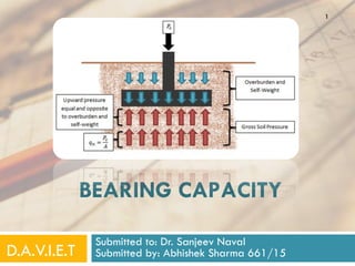
  • 5. Bearing capacity (q): The load-carrying capacity of foundation soil or rock which enables it to bear and transmit loads from a structure. ULTIMATE bearing capacity (qult): Maximum pressure which a foundation can withstand without the occurrence of shear failure of the foundation. Gross Ultimate bearing capacity: The bearing capacity inclusive of the pressure exerted by the weight of the soil standing on the foundation, or the ‘surcharge’ pressure, as it is sometimes called. Net Ultimate bearing capacity (qnu): Gross bearing capacity minus the original overburden pressure or surcharge pressure at the foundation level; obviously, this will be the same as the gross capacity when the depth of foundation is zero, i.e., the structure is founded at ground level. 5ABHISHEK SHARMA 661
  • 6. Safe bearing capacity (qs ): Ultimate bearing capacity divided by the factor of safety. The factor of safety in foundation may range from 2 to 5, The factor of safety should be applied to the net ultimate bearing capacity the surcharge pressure due to depth of the foundation should then be added to get the safe bearing capacity. It is thus the maximum intensity of loading which can be transmitted to the soil without the risk of shear failure, irrespective of the settlement that may occur. 6 ABHISHEK SHARMA 661
  • 7. GROSS SAFE BEARING CAPACITY: It is the maximum gross intensity (inclusive of overburden pressure) of loading at the base of the foundation that the soil can support before failing in shear NET SAFE BEARING CAPACITY (qns ): It is the maximum net intensity (exclusive of overburden pressure) of loading at the base of the foundation that the soil can support without the risk of shear failure. ALLOWABLE BEARING PRESSURE (qa ): The maximum allowable net loading intensity on the soil at which the soil never fails in shear and doesn’t pose any excessive settlement or can be say that the settlements are under permissible limits. 7 ABHISHEK SHARMA 661
  • 8. Ultimate limit state defines a limiting stress or force that should not be exceeded by any conceivable or anticipated loading during the design life of a foundation or any geotechnical system. Serviceability limit state defines a limiting deformation or settlement of a foundation, which, if exceeded, will impair the function of the structure that it supports. 8 ABHISHEK SHARMA 661
  • 9. 9 AS PER IS 6403 : 1981 Net Loading Intensity: The net loading intensity on the foundation is the gross intensity of loading minus the weight of displaced soil above the foundation base. Ultimate Bearing Capacity : The intensity of loading at the base or the foundation which would cause shear failure of the soil support. Safe Bearing capacity : Maximum intensity of loading that the foundation will safely carry without the risk of shear failure of soil irrespective of any settlement that may occur. Safe Bearing Pressure or Net Soil Pressure : The Intensity of loading that will cause a permissible settlement or specified settlement of the structure. ABHISHEK SHARMA 661
  • 10. 10 Allowable Bearing Capacity : The net intensity of loading which the foundation will carry without undergoing settlement in excess or the permissible value for the structure under consideration but not exceeding net safebearing capacity ABHISHEK SHARMA 661
  • 11. 3. TYPES OF FAILURE IN SOIL 11 Experimental investigations have indicated that foundations on dense sand with relative density greater than 70 percent fail suddenly with pronounced peak resistance when the settlement reaches about 7 percent of the foundation width. The failure is accompanied by the appearance of failure surfaces and by considerable bulging of a sheared mass of sand as shown in Fig. This type of failure is designated as general shear failure by Terzaghi (1943) ABHISHEK SHARMA 661
  • 13. 13 Foundations on sand of relative density lying between 35 and 70 percent do not show a sudden failure. As the settlement exceeds about 8 percent of the foundation width, bulging of sand starts at the surface. At settlements of about 15 percent of foundation width, a visible boundary of sheared zones at the surface appears. However, the peak of base resistance may never be reached. This type of failure is termed local shear failure, Fig. ABHISHEK SHARMA 661
  • 14. 14 Foundations on relatively loose sand with relative density less than 35 percent penetrate into the soil without any bulging of the sand surface. The base resistance gradually increases as settlement progresses. The rate of settlement, however, increases and reaches a maximum at a settlement of about 15 to 20 percent of the foundation width. Sudden jerks or shears can be observed as soon as the settlement reaches about 6 to 8 percent of the foundation width. The failure surface, which is vertical or slightly inclined and follows the perimeter of the base, never reaches the sand surface. This type of failure is designated as punching shear failure by Vesic (1963) ABHISHEK SHARMA 661
  • 16. 16 The approximate limits of types of failure to be affected as relative depth DF / B and relative density of sand, Dr, vary are shown in Fig. (Vesic, 1963). General shear failure occur when φ is more than or equal to 380. Local Shear Failure occur when φ is than or equal to 280
  • 17. 4.CRITERIA FOR THE DETERMINATION OF BEARING CAPACITY 1. LOCATION AND DEPTH: A foundation must be properly located and founded at such a depth that its performance does not affected by factors such as lateral expulsion of soil from beneath the foundation, seasonal volume changes, presence of adjoining structures etc. 17 ABHISHEK SHARMA 661
  • 18. 2. Shear failure of the foundation or bearing capacity failure, as it is sometimes called, shall not occur. (This is associated with plastic flow of the soil material underneath the foundation, and lateral expulsion of the soil from underneath the footing of the foundation); and, 3. The probable settlements, differential as well as total, of the foundation must be limited to safe, tolerable or acceptable magnitudes. In other words, the anticipated settlement under the applied pressure on the foundation should not be detrimental to the stability of the structure. Last two criteria are known as the shear strength criterion, and settlement criterion, respectively. The design value of the safe bearing capacity, obviously, would be the smaller of the two values, obtained from these two criteria.18 ABHISHEK SHARMA 661
  • 19. 5.FACTORS AFFECTING BEARING CAPACITY (i) Nature of soil and its physical and engineering properties; (ii) Nature of the foundation and other details such as the size, shape, depth below the ground surface and rigidity of the structure; (iii) Total and differential settlements that the structure can withstand without functional failure; (iv) Location of the ground water table relative to the level of the foundation; and (v) Initial stresses, if any. 19 ABHISHEK SHARMA 661
  • 20. 6.METHODS OF DETERMINING BEARING CAPACITY (i) Bearing capacity tables in various building codes (ii) Analytical methods (iii) Plate bearing tests (iv) Penetration tests (v) Model tests and prototype tests (vi) Laboratory tests 20 ABHISHEK SHARMA 661
  • 21. ACCORDING TO OUR SYLLABUS FOLLOWING METHODS ARE PRESCRIBED IN DETAIL ONE BY ONE. 1. The theory of elasticity—Schleicher’s method. 2. The classical earth pressure theory—Rankine’s method, Pauker’s method and Bell’s method. 3. The theory of plasticity—Fellenius’ method, Prandtl’s method, Terzaghi’s method, Meyerhof’s method, Skempton’s method, Hansen’s method and Balla’s method. PLATE LOAD TEST AND PENETRATION TEST ANALYTIC APPROACH 21 ABHISHEK SHARMA 661
  • 22. 7. RANKINE METHOD This method, based on Rankine’s earth pressure theory, is too approximate and conservative for practical use. 22 WILLIAM RANKINE (1820–1872) ABHISHEK SHARMA 661
  • 23. 23 Rankine uses the relationship between principal stresses at limiting equilibrium conditions of soil elements, one located just beneath the footing and the other just outside it as shown in Fig. ABHISHEK SHARMA 661
  • 24. In element I, just beneath the footing, at the base level of the foundation, the applied pressure qult is the major principal stress; under its influence, the soil adjacent to the element tends get pushed out, creating active conditions. The active pressure is σ on the vertical faces to the element. From the relationship between the principal stresses at limiting equilibrium relating to the active state, we have: ……..EQ.1 24 ABHISHEK SHARMA 661
  • 25. In element II, just outside the footing, at the base level of the foundation, the tendency of the soil adjacent to the element is to compress, creating passive conditions. The pressure σ on the vertical faces of the element will thus be the passive resistance. This will thus be the major principal stress and the corresponding minor principal stress is q(= γ.Df) ……..EQ.2 25 ABHISHEK SHARMA 661
  • 26. FROM EQ.1 AND EQ.2 ……..EQ.3 This gives the bearing capacity of the footing. It does not appear to take into account the size of the footing. to give Df , which is termed the minimum depth required for a foundation: ……..EQ.4 It does not appear to take into account the size of the footing26 ABHISHEK SHARMA 661
  • 27. An alternative approach based on Rankine’s earth pressure theory which takes into account the size b of the footing is as follows: It is assumed that rupture in the soil takes place along CBD and CFG symmetrically. The failure zones are made of two wedges as shown. It is sufficient to consider the equilibrium of one half. 27 ABHISHEK SHARMA 661
  • 28. Wedge I is Rankine’s active wedge, pushed downwards by qult on CA; consequently the vertical face AB will be pushed outward. Wedge II is Rankine’s passive wedge. The pressure P on face AB of wedge I will be the same as that which acts on face AB of wedge II; consequently, the soil wedge II is pushed up. The surcharge, q = γ.Df, due to the depth of footing resists this. ……..EQ.528 ABHISHEK SHARMA 661 ABHISHEK SHARMA 661
  • 29. from Rankine’s theory for the case with surcharge. From Wedge I, similarly, …..EQ.6 Equating the two values of P from EQ.5.5 and EQ.6, we get …..EQ.7 This is written as …..EQ.8 …..EQ.9 …..EQ.10 Both are known as BEARING CAPACITY FACTORS 29 ABHISHEK SHARMA 661
  • 30. 8.Prandtl’s Method 30 Prandtl analyzed the plastic failure in metals when punched by hard metal punchers (Prandtl, 1920). This analysis has been adapted to soil when loaded to shear failure by a relatively rigid foundation (Prandtl, 1921). Ludwig Prandtl 4 February 1875 - 15 August 1953 ABHISHEK SHARMA 661
  • 31. 31 The assumptions in Prandtl’s theory are: (i) The soil is homogeneous, isotropic and weightless. (ii) The Mohr-Coulomb equation for failure envelope τ = c + σ tan υ is valid for the soil, (iii) Wedges I and III act as rigid bodies. The zones in Sectors II deform plastically. In the plastic zones all radius vectors or planes through A and B are failure planes and the curved boundary is a logarithmic spiral. (iv) Wedge I is elastically pushed down, tending to push zones III upward and outward, which is resisted by the passive resistance of soil in these zones. (v) The stress in the elastic zone I is transmitted hydrostatically in all directions. ABHISHEK SHARMA 661
  • 32. 32 qult = c cot φ (Nφ . eπ tan φ – 1) This is Prandtl’s expression for ultimate bearing capacity of a c – υ soil. …..EQ.11
  • 33. 33 purely cohesive soils, φ = 0 qult = (π + 2)c = 5.14c Discussion of Prandtl’s Theory (i) Prandtl’s theory is based on an assumed compound rupture surface, consisting of an arc of a logarithmic spiral and tangents to the spiral. (ii) It is developed for a smooth and long strip footing, resting on the ground surface. (iii) Prandtl’s compound rupture surface corresponds fairly well with the mode of failure along curvilinear rupture surfaces observed from experiments. (iv) Prandtl’s expression, as originally derived, does not include the size of the footing. …..EQ.12 ABHISHEK SHARMA 661
  • 34. 9. TERZAGHI METHOD (1943). Terzaghi’s method is, in fact, an extension and improved modification of Pandtl’s 34 ABHISHEK SHARMA 661 Karl von Terzaghi 2 October 1883 -- 25 October 1963 ABHISHEK SHARMA 661
  • 35. 35 The soil is a semi-infinite, homogeneous, isotropic, weightless, rigid–plastic material. ASSUMPTIONS: The embedment depth is not greater than the width of the footing (Df < B). General shear failure occurs & The base of the footing is rough. The soil above the footing base can be replaced by a surcharge stress. This, in effect, means that the shearing resistance of the soil located above the base is neglected. ABHISHEK SHARMA 661
  • 36. The zone of plastic equilibrium, CDEFG, can be subdivided into I a wedge-shaped zone located beneath the loaded strip, in which the major principal stresses are vertical, II two zones of radial shear, BCD and ACG, emanating from the outer edges of the loaded strip, with their boundaries making angles (45° – φ/2) and φ with the horizontal, and III two passive Rankine zones, AGF and BDE, with their boundaries making angles (45° – υ/2) with the horizontal.36 ABHISHEK SHARMA 661
  • 37. The adhesion force Ca on the faces AC and BC is given by: …..EQ.13 Considering a unit length of the footing and the equilibrium of wedge ABC, the vertical components of all forces must sum up to zero. …..EQ.14 …..EQ.15 …..EQ.16 The weight of the soil in the wedge is given by 37 ABHISHEK SHARMA 661
  • 38. For the simpler case of Df = 0 and c = 0, q = 0—that is, if the base of the footing rests on the horizontal surface of a mass of cohesionless sand, we have: …..EQ.17 Here Kpγ is the coefficient of passive earth pressure for c = 0, α = 180° – υ, and δ = υ ; that is, it is the value purely due to the weight of the soil. 38 ABHISHEK SHARMA 661
  • 39. …..EQ.18 …..EQ.19 …..EQ.20 Substituting EQ.15 in EQ.14 The value of Kpγ is obtained by means of the spiral or the friction circle method. Nγ is called the ‘‘bearing-capacity factor’’ expressing the effect of the weight of the soil wedge, ABC, of a cohesionless soil. 39 ABHISHEK SHARMA 661
  • 40. For the calculation of the bearing capacity of a cohesive soil, the computation of Pp involves a considerable amount of labour. Terzaghi, therefore, advocated a simplified approach, which is based on the equation …..EQ.21 where Ppn = normal component of the passive earth pressure on a plane contact face with a height H, α = slope angle of the contact face, and Kpc, Kpq, and Kpγ = coefficients whose values are indpendent of H and γ. In the present case, 40 ABHISHEK SHARMA 661
  • 41. Also the total passive earth pressure Pp on the contact face is equal to …..EQ.22 where (cKpc + qKpq) = Ppn is the normal component of the passive earth pressure comprehending the effect of cohesion and surcharge. Combining this equation with Eq. 14, we have …..EQ.23 41 ABHISHEK SHARMA 661
  • 42. If the soil wedge, ABC, is assumed weightless (γ = 0) (Prandtl, 1920), Eq. (21) takes the form …..EQ.24 The factors Nc and Nq are pure numbers whose values depend only on the value φ in Coulomb’s equation. On the other hand, if c = 0 and q = 0, γ being greater than zero, the bearing capacity is given by Eqs. 17 and 18: 42 ABHISHEK SHARMA 661
  • 43. If the values c, Df, and γ are greater than zero, …..EQ.25 This is called ‘‘Terzaghi’s general bearing capacity formula’’. The coefficients Nc, Nq, and Nγ are called ‘‘bearing capacity factors’’ for shallow continuous footings. 43 ABHISHEK SHARMA 661
  • 44. The problem of Nc and Nq has been rigorously solved by means of Airy’s stress function (Prandtl 1920, Reissner, 1924), for the condition γ = 0: …..EQ.26 …..EQ.27 …..EQ.28 The values Nc and Nq depend only on the value of υ. 44 ABHISHEK SHARMA 661
  • 45. Bearing capacity of a strip footing with a rough base on the ground surface is given by, qult = 5.7c …..EQ.29 For strip footing at a depth Df in a purely cohesive soil qult = 5.7c + γDf. …..EQ.30 Equation 23, along with the bearing capacity factors Nc, Nq and Nγ are valid for ‘general shear failure’. For ‘local shear failure’, as given by Terzaghi : c′ = (2/3)c tan φ′ = (2/3) tan φ …..EQ.31 …..EQ.32 45 ABHISHEK SHARMA 661
  • 46. for local shear failure, …..EQ.33 Terzaghi’s bearing capacity factors are plotted in Fig. 46 ABHISHEK SHARMA 661
  • 47. As a general guideline, if failure occurs at less than 5% strain and if density index is greater than 70%, general shear failure may be assumed, if the strain at failure is 10% to 20% and if the density index is less than 20%, local shear failure may be assumed, and, for intermediate situations punching shear, linear interpolation of the factors may be employed. QUICK NOTE 47 ABHISHEK SHARMA 661
  • 48. The bearing capacity factors of Terzaghi are tabulated in following Table 48 ABHISHEK SHARMA 661
  • 49. Bearing capacity of shallow circular and square footings Bearing capacity of circular footings has been proposed by Terzaghi as follows, qultc = 1.3 cNc + γDf Nq + 0.3 γ d Nγ …..EQ.34 where d = diameter of the circular footing. The critical load for the footing is given by …..EQ.35 49 ABHISHEK SHARMA 661
  • 50. Similarly, the bearing capacity of a square footing of side b is: qults = 1.3 cNc + γDfNq + 0.4 γb Nγ …..EQ.36 Qults = (b2) . Qults The critical load for the footing is given by For a continuous footing of width b, it is already seen that, qult = cNc + γDf Nq + 0.5 γ b Nγ …..EQ.37 …..EQ.38 50 ABHISHEK SHARMA 661
  • 51. Thus, the bearing capacity of a circular footing of diameter equal to the width of a continuous footing is 1.3 times that of the continuous footing, or at least nearly so, if the footings are founded in a purely cohesive soil (φ = 0); the bearing capacity of a square footing of side equal to the width of a continuous footing also bears a similar relation to that of the continuous footing under similar conditions just cited. Further, the corresponding ratios are 0.6 and 0.8 in the case of circular footing and square footing, respectively, when the footings are founded in a purely cohesionless soil (c = 0). QUICK NOTE 51 ABHISHEK SHARMA 661
  • 52. 10. SKEMPTON METHOD (1951) He found that the factor Nc is a function of the depth of foundation and also of its shape. 52 ABHISHEK SHARMA 661 Alec Skempton 4 June 1914 - 9 August 2001
  • 53. 53 The net ultimate bearing capacity is given by: qnet ult = c . Nc …..EQ.39 Strip footings: Nc = 5 (1 + 0.2 Df /b) with a limiting value of Nc of 7.5 for Df /b > 2.5. …..EQ.40 Square or Circular footings: Nc = 6(1 + 0.2Df /b) with a limiting value of Nc of 9.0 for Df /b >2.5. (b is the side of square or diameter of circular footing). EQ.41 ….. ABHISHEK SHARMA 661
  • 54. for Df /b ≤ 2.5, for Df /b > 2.5, b = width of the rectangular footing, L = length of the rectangular footing. Nc = 7.5 (1 + 0.2 b/L) …..EQ.42 & EQ.43 54 ABHISHEK SHARMA 661
  • 55. For a surface footing of square or circular shape on purely cohesive soil Qnet ult = 6c ...(Eq. 44) as against 7.4c from Terzaghi’s theory. It must be noted that Terzaghi’s theory is limited to shallow foundations wherein Df /b ≤ 1, but Skempton’s equations do not suffer from such a limitation. QUICK NOTE 55 ABHISHEK SHARMA 661
  • 56. 11. Brinch Hansen’s Method 56 Brinch Hansen (1961) has proposed the following semi- empirical equation for the bearing capacity of a footing, as a generalisation of the Terzaghi equation: …..EQ.45 Qult = vertical component of the total load A = effective area of the footing q = overburden pressure at the foundation level (= γ . Df), Nq = Nυ . eπ tan υ Nc = (Nq – 1) cot φ Nγ = 1.8 (Nq – 1) tan υ (Nυ = tan2 (45° + υ/2), with the usual notation.) ABHISHEK SHARMA 661
  • 57. 57 S = shape factors d = depth factors, and i = inclination factors. Brinch Hansen’s shape factors Brinch Hansen’s depth factors ABHISHEK SHARMA 661
  • 58. 58 Brinch Hansen’s inclination factors Revised values of inclination factors: …..EQ.46 …..EQ.47 …..EQ.48But, for φ = 0°, ABHISHEK SHARMA 661
  • 59. 12. Balla’s Method 59 Balla has proposed a theory for the bearing capacity of continuous footings (Balla 1962). The theory appears to give values which are in good agreement with field test results for footings founded in cohesionless soils. The form of the bearing capacity equation is the same as that of Terzaghi: …..EQ.49 ABHISHEK SHARMA 661
  • 60. 60 But the equations for the bearing capacity factors are cumbersome to solve without the aid of a digital computer. Therefore, it is generally recommended that Balla’s charts be used for the determination of these factors. ABHISHEK SHARMA 661
  • 61. 61 The limitations are that it should be used when Df / b ≤ 1.5 and that it is applicable to continuous footings only. ABHISHEK SHARMA 661
  • 62. 13. Meyerhof’s Method 62 The important difference between Terzaghi’s and Meyerhof’s approaches is that the latter considers the shearing resistance of the soil above the base of the foundation, while the former ignores it. Thus, Meyerhof allows the failure zones to extend up to the ground surface (Meyerhof, 1951). ABHISHEK SHARMA 661
  • 63. 63 Zone I ABC ... elastic Zone II BCD ... radial shear Zone III BDEF ... mixed shear wherein Nc, Nq and Nγ are ‘‘Meyerhof’s bearing capacity factors’’, which depend not only on υ, but also on the depth and shape of the foundation and roughness of the base. Meyerhof’s factors are more difficult to obtain than Terzaghi’s, and have been presented in the form of charts by Meyerhof. For strip footings: Nc = 5.5(1 + 0.25 Df/b) with a limiting value of 8.25 for Nc for Df /b > 2.5. …..EQ.50 For square or circular footings: Nc = 6.2 (1 + 0.32 Df /b) with a limiting value of 9.0 for Nc for Df /b > 2.5. (b is the side of a square or diameter of circular footing). ABHISHEK SHARMA 661
  • 64. 14. Vesic's Bearing Capacity Theory 64 Vesic(1973) confirmed that the basic nature of failure surfaces in soil as suggested by Terzaghi as incorrect. However, the angle which the inclined surfaces make with the horizontal was found to be closer to 45 + υ/2 instead of υ . The values of the bearing capacity factors , , for a given angle of shearing resistance change if above modification is incorporated in the analysis as under …..EQ.51 …..EQ.52 …..EQ.53 ABHISHEK SHARMA 661
  • 65. 65 eqns(51)was proposed by Prandtl(1921),and eqn(52) was given by Reissner (1924). Caquot and Keisner (1953) and Vesic (1973) gave eqn (53) …..EQ.54 ABHISHEK SHARMA 661
  • 67. 15. IS 6403:1981 METHOD 67 …..EQ.55 If the water table is at or below a depth of Df +B, measured from the ground surface, w’=1. If the water table rises to the base of the footing or above, w’=0.5. If the water table lies in between then the value is obtained by linear interpolation. The shape factors given by Hansen and inclination factors as given by Vesic are used. ABHISHEK SHARMA 661
  • 68. 68 For cohesive soils: Nc = 5.14 ABHISHEK SHARMA 661
  • 69. 16. EFFECT OF WATER TABLE ON BEARING CAPACITY Water in soil is known to affect its unit weight and also the shear parameters c and φ. When the soil is submerged under water, the effective unit weight γ′ is to be used in the computation of bearing capacity. NOTE: Effective unit weight γ′ is roughly half the saturated unit weight; consequently there will be about 50% reduction in the value of the corresponding term in the bearing capacity formula. 69 ABHISHEK SHARMA 661
  • 70. • If the water table is at the level of the base of the footing, γ′ is to be used for γ in the third term, a reduction factor of 0.5 is to be applied to the third term. • For any location of the water table intermediate between the base of the footing and a depth equal to the width of the footing below its base, a suitable linear interpolation of the necessary reduction is suggested. • If the water table is above the base of the footing, the reduction factor for the third term is obviously limited to the maximum of 0.5.70 ABHISHEK SHARMA 661
  • 71. • The maximum reduction of 0.5 is indicated for the second term when the water table is at the ground level itself (or above it), since γ′ is to be used for γ in the second term. • While no reduction in the second term is required when the water table is at or below the base of the footing, • In the case of purely cohesive soils, since φ ≈ 0°, Nq = 1 and Nγ = 0, • Net ultimate bearing capacity is given by c . Nc, which is virtually unaffected by the water table, if it is below the base of the footing. 71 ABHISHEK SHARMA 661
  • 72. • If the water table is at the ground level, only the gross bearing capacity is reduced by 50% of the surcharge term γ.Df (Nq = 1), while the net value is again only c . Nc. • In the case of purely cohesionless soils, since c = 0, and φ > 0, and Nq and Nγ are significantly high, For locations of ground water table within a depth of the width of the foundation below the base and the ground level, the equation for the ultimate bearing capacity may be modified as follows: ...(Eq. 56) *appropriate multiplying factor should be used for isolated footings. **Appropriate shape factor. 72 ABHISHEK SHARMA 661
  • 73. c′ = effective cohesion Nc, Nq, and Nγ = bearing capacity factors based on φ′ Rq and Rγ = reduction factors for the terms involving Nq and Nγ owing to the effect of water table. Rq and Rγ may be obtained as follows, from Fig. zq = 0...Rq = 0.5 zγ = 0...Rγ = 0.5 zq = Df...Rq = 1.0 zγ = b...Rγ = 1.0 73 ABHISHEK SHARMA 661
  • 74. ...(Eq. 57) ...(Eq. 58) Note. • For zq > Df (the water table is below the base of the footing), Rq is limited to 1.0. • For 0 ≤ zq ≤ Df (the water table is above the base of the footing), Rγ is limited to 0.5. • for zq > (Df + b) or zγ > b, Rq as well as Rγ are limited to 1.0. • For zq = 0, Rq as well as Rγ are limited to 0.5. 74 ABHISHEK SHARMA 661
  • 75. 17. FOUNDATION SETTLEMENTS Settlement total settlement and differential settlement of foundations and consequently of the structures above the foundations. Source of Settlement (i) Elastic compression of the foundation and the underlying soil, giving rise to what is known as ‘immediate’, ‘contact’, ‘initial’, or ‘distortion’ settlement, (ii) Plastic compression of the underlying soil, giving rise to consolidation, settlement of fine grained soils, both primary and secondary, (iii) Ground water lowering, especially repeated lowering and raising of ground water level in loose granular soils and drainage without adequate filter protection, 75 ABHISHEK SHARMA 661
  • 76. (iv) Vibration due to pile driving, blasting and oscillating machinery in granular soils, (v) Seasonal swelling and shrinkage of expansive clays, (vi) Surface erosion, creep or landslides in earth slopes, (vii) Miscellaneous sources such as adjacent excavation, mining subsidence and underground erosion. The settlements from the first two sources alone may be predicted with a fair degree of confidence. 76 ABHISHEK SHARMA 661
  • 77. The total settlement may be considered to consist of the following contributions: (a) Initial settlement or elastic compression. (b) Consolidation settlement or primary compression. (c) Secondary settlement or secondary compression Initial Settlement or Elastic Compression This is also referred to as the ‘distortion settlement’ or ‘contact settlement’ and is usually taken to occur immediately on application of the foundation load. Such immediate settlement in the case of partially saturated soils is primarily due to the expulsion of gases and to the elastic compression and rearrangement of particles. In the case of saturated soils immediate settlement is considered to be the result of vertical soil compression 77 ABHISHEK SHARMA 661
  • 78. Immediate Settlement in Cohesionless Soils • Standard Penetration Test (De Beer and Martens, 1957). This method has been developed for use with the Dutch Cone Penetrometer but can be adapted for the standard penetration test. The immediate settlement, Si, is given by: ...(Eq. 58) H = thickness of the layer getting compressed, σ0 = effective overburden pressure at the centre of the layer before any excavation or application of load, Δσ = vertical stress increment at the centre of the layer, and Cs = compressibility constant, given by: ...(Eq. 59) Cr being the static cone resistance (in kN/m2), and σ0 being the effective overburden pressure at the point tested. 78 ABHISHEK SHARMA 661
  • 79. The value of Cr obtained from the Dutch Cone penetration test must be correlated to the recorded number of blows, N, obtained from the standard penetration test. According to Meigh and Nixon (1961), Cr ranged from 430N (kN/m2) to 1930N (kN/m2). However, Cr is more commonly taken as 400 N (kN/m2) as proposed by Meyerhof (1956). 79 ABHISHEK SHARMA 661
  • 80. The use of charts: The actual number of blows, N, from the standard penetration test has to be corrected, under certain circumstances to obtain N′, the corrected value. Thornburn (1963) has given a set of curves to obtain N′ from N. He also extended the graphical relationship given by Terzaghi and Peck (1948) between the settlement of a 305 mm square plate under a given pressure and the N′-value of the soil immediately beneath it, as shown in Fig. For determining the settlement, Sf, of a square foundation on a deep layer of cohesionless soil by using Terzaghi and Peck’s formula: ...(Eq. 60) Sp = Settlement of a 305 mm-square plate, obtained from the chart and, B = Width of foundation (metres)80 ABHISHEK SHARMA 661
  • 81. The chart is applicable for deep layers only, that is, for layers of thickness not less than 4B below the foundation. For rectangular foundations, a shape factor should presumably be used. It is as follows: Settlement of a rectangular foundation of width B = Settlement of square foundation of size B × shape factor. 81 ABHISHEK SHARMA 661
  • 82. Immediate Settlement in Cohesive Soils The immediate settlement of a flexible foundation, according to Terzaghi (1943), is given by: ...(Eq. 61) Si = immediate settlement at a corner of a rectangular flexible foundation of size L × B, B = Width of the foundation, q = Uniform pressure on the foundation, Es = Modulus of elasticity of the soil beneath the foundation, ν = Poisson’s ratio of the soil, and It = Influence Value, which is dependent on L/B 82 ABHISHEK SHARMA 661
  • 83. Si, for a rectangular foundation on the surface of a semi-elastic medium is given by: ...(Eq. 62) B = width of the rectangular foundation of size L × B, q = uniform intensity of pressure, Es = modulus of elasticity of the soil beneath the foundation, ν = Poisson’s ratio of the soil, and Is = influence factor which depends upon L/B. Skempton (1951) gives the following values of Is : 83 ABHISHEK SHARMA 661
  • 84. Immediate Settlement of a Thin Clay Layer For cases when the thickness of the layer is less than 4B, Steinbrenner (1934) prepared coefficients. The immediate settlement at the corners of a rectangular foundation on an infinite layer is given by: ...(Eq. 63) 84 ABHISHEK SHARMA 661
  • 86. Permissible Settlements There are two main ill-effects of differential settlements: (i) the architectural effect (cracking of plaster, for example) and (ii) the structural effect (redistribution of moments and shears, for example, which may ultimately lead to failure). Terzaghi and Peck (1948) specify a permissible differential settlement of 20 mm between adjacent columns and recommend that foundations on sand be designed for a total settlement of 25 mm. Skempton and MacDonald (1956) specify that the angular rotation or distortion between adjacent columns in clay should not exceed 1/300, although the total settlement may go up to 100 mm Sowers (1957) recommends, in his discussion of the paper by Polshin and Pokar (1957) a maximum differential settlement of 1/500 for brick buildings and 1/5000 for foundations of turbogenerators. 86 ABHISHEK SHARMA 661
  • 87. Bozozuk (1962) summarised his investigations in Ottawa as follows: (IS: 1904-1961) recommends a permissible total settlement of 65 mm for isolated foundations on clay, 40 mm for isolated foundations on sand, 65 to 100 mm for rafts on clay and 40 to 65 mm for rafts on sand. The permissible differential settlement is 40 mm for foundations on clay and 25 mm for foundations on sand. The angular distortion in the case of large framed structures must not exceed 1/500 normally and 1/1000 if all kinds of minor damage also are to be prevented.87 ABHISHEK SHARMA 661
  • 88. Remedial Measures Against Harmful Settlements 1. Removal of soft soil strata, consistent with economy. 2. The use of properly designed and constructed pile foundations 3. Provision for lateral restraint against lateral expulsion of soil mass from underneath the footing of a foundation. 4. Building slowly on cohesive soils to avoid lateral expansion of a soil mass and to give time for the pore water to be expelled by the surcharge load. 5. Reduction of contact pressure on the soil; more appropriately, proper adjustment between pressure, shape and size of the foundation in order to attain uniform settlements underneath the structure. 6. Preconsolidation of a building site long enough for the expected load, depending upon the tolerable settlements; 88 ABHISHEK SHARMA 661
  • 89. 18. CONTACT PRESSURE ‘Contact pressure’ is the actual pressure transmitted from the foundation to the soil. A uniformly loaded foundation will not necessarily transmit a uniform contact pressure to the soil. This is possible only if the foundation is perfectly ‘flexible’; 89 ABHISHEK SHARMA 661
  • 90. 19. PLATE LOAD TEST The test essentially consists in loading a rigid plate at the foundation level, increasing the load in arbitrary increments, and determining the settlements corresponding to each load after the settlement has nearly ceased each time a load increment is applied. The nature of the load applied may be gravity loading or dead weights on an improvised platform or reaction loading by using a hydraulic jack. The reaction of the jack load is taken by a cross beam or a steel truss anchored suitably at both ends. Test plates are usually square or circular, the size ranging from 300 to 750 mm (side or diameter); the minimum thickness recommended is 25 mm for providing sufficient rigidity. Jack-loading is superior in terms of accuracy and uniformity of loading. Settlement of the test plate is measured by means of at least two or three dial gauges with a least count of 0.02 mm. 90 ABHISHEK SHARMA 661
  • 92. The test pit should be at least five times as wide as the test plate and the bottom of the test plate should correspond to the proposed foundation level. At the centre of the pit, a small square hole is made the size being that of the test plate and the depth being such that, ...(Eq. 64) 92 ABHISHEK SHARMA 661
  • 93. Bigger size plates are preferred in cohesive soils. The test procedure is given in IS: 1888–1982 (Revised). The procedure, in brief, is as follows: (i) After excavating the pit of required size and levelling the base, the test plate is seated over the ground. A little sand may be spread below the plate for even support. If ground water is encountered, it should be lowered slightly below the base by means of pumping. (ii) A seating pressure of 7.0 kN/m2 (70 g/cm2) is applied and released before actual loading is commenced. (iii) The first increment of load, say about one-tenth of the anticipated ultimate bearing capacity, is applied. Settlements are recorded with the aid of the dial gauges after 1 min., 4 min., 10 min., 20 min., 40 min., and 60 min., and later on at hourly intervals until the rate of settlement is less than 0.02 mm/hour, or at least for 24 hours. 93 ABHISHEK SHARMA 661
  • 94. (iv) The test is continued until a load of about 1.5 times the anticipated ultimate load is applied. According to another school of thought, a settlement at which failure occurs or at least 2.5 cms should be reached. (v) From the results of the test, a plot should be made between pressure and settlement, which is usually referred to as the ‘‘load- settlement curve’’, rather loosely. The bearing capacity is determined from this plot, which is dealt with in the next subsection. Load-Settlement Curves Load-Settlement curves or pressure-settlement curves to be more precise, are obtained as a result of loading tests either in the laboratory or in the field, oedometer tests being an example in the laboratory and plate bearing test, in the field. 94 ABHISHEK SHARMA 661
  • 95. Curve I is typical of dense sand or gravel or stiff clay, wherein general shear failure occurs. Curve II is typical of loose sand or soft clay, wherein local shear failure occurs. Curve III is typical of many c – φ soils which exhibit characteristics intermediate between the above two. 95 ABHISHEK SHARMA 661
  • 96. Determination of bearing capacity from plate load test (Terzaghi and Peck, 1948): ...(Eq. 65) S = settlement of the proposed foundation (mm), Sp = settlement of the test plate (mm), b = size of the proposed foundation (m), and bp = size of the test plate (m). This is applicable for sands. 96 ABHISHEK SHARMA 661
  • 97. The relationship is simpler for clays, since the modulus value Es, for clays is reasonably constant: ...(Eq. 66) Sp = Settlement of a test plate of 300 mm square size, and S = Settlement of a footing of width b. The method for the determination of the bearing capacity of a footing of width b should be apparent now. The permissible settlement value, such as 25 mm, should be substituted in the equation that is applicable (Eq. 50 to 51) ; and the Sp, the settlement of the plate must be calculated. From the load-settlement curve, the pressure corresponding to the computed settlement Sp, is the required value of the ultimate bearing capacity, qult, for the footing.97 ABHISHEK SHARMA 661
  • 98. Limitations of Plate Load Tests (i) Size (plate) effects are very important. (ii) Consolidation settlements in cohesive soils, which may take years, cannot be predicted, (iii) Results from plate load test are not recommended to be used for the design of strip footings, (iv) The load test results reflect the characteristics of the soil located only within a depth of about twice the width of the plate. Thus, it may be seen that interpretation and use of the plate load test results requires great care and judgment, on the part of the foundation engineer. 98 ABHISHEK SHARMA 661
  • 99. 20. BEARING CAPACITY FROM PENETRATION TESTS Terzaghi and Peck have prepared charts for allowable bearing pressure, based on a standard allowable settlement, for footings of known widths on sand, whose N-values are known. 99 ABHISHEK SHARMA 661
  • 100. Above figures do not apply to gravels or those soils containing a large percentage of gravels. These charts have been prepared on the assumption that the water table is at a depth greater than the width of the footing below the base of the footing. If the water table is located at the base of the footing, the allowable pressure is taken as half that obtained from the charts. 100 ABHISHEK SHARMA 661
  • 101. Charts given by Peck, Hanson and Thornburn (1953) may be used for the determination of allowable bearing pressure for a specific allowable settlement of 25 mm or 40 mm, Fig.1 allowable bearing pressure for 40mm settlement. Fig.2 allowable soil pressure101 ABHISHEK SHARMA 661
  • 102. 102 Teng (1969) has proposed the following equation for the graphical relationship of Terzaghi and Peck for a settlement of 25 mm: ...(Eq. 67) where qna = net allowable soil pressure in kN/m2 for a settlement of 25 mm, N = Standard penetration value corrected for overburden pressure and other applicable factors, b = width of footing in metres, Rγ = correction factor for location of water table, (Eq.56) and Rd = Depth factor (= 1 + Df /b) ≤ 2. where Df = depth of footing in metres. The modified equation of Teng is as follows: ...(Eq. 68) ABHISHEK SHARMA 661
  • 103. 103 Meyerhof (1956) has proposed slightly different equations for a settlement of 25 mm, but these yield almost the same results as Teng’s equation: ...(Eq. 69) ...(Eq. 70) Modified equation of Meyerhof is as follows: ...(Eq. 71) ...(Eq. 72) ABHISHEK SHARMA 661
  • 104. The I.S. code of practice gives Eq. 73 for a settlement of 40 mm; but, it does not consider the depth effect. ...(Eq. 73) ...(Eq. 73 a) qna = net allowable soil pressure in kN/m2 for a settlement of 25 mm, N = Standard penetration value corrected for overburden pressure and other applicable factors, b = width of footing in metres, Rγ = correction factor for location of water table, (Eq.52) Rd = Depth factor (= 1 + Df /b) ≤ 2. Df = depth of footing in metres. 104 ABHISHEK SHARMA 661
  • 105. 105 Teng (1969) also gives the following equations for bearing capacity of sands based on the criterion of shear failure: ...(Eq. 74) ...(Eq. 75) N = Standard penetration value, after applying the necessary corrections, b = width of continuous footing (side, if square, and diameter, if circular in metres), Df = depth of footing in metres, and Rγ and Rq = correction factors for the position of the ground water table, defined in Eqs. 52 & 53. ABHISHEK SHARMA 661
  • 106. 21. BEARING CAPACITY OF CLAYS 106 For pure clays, φ = 0°. (for square or circular footings, c being the cohesion.) ...(Eq. 76) ABHISHEK SHARMA 661
  • 107. QUICK NOTE Skempton’s equations are preferred for rectangular footings in pure clay. Correlation of cohesion and consistency of clays with N-values is not reliable. Unconfined compression test is recommended for evaluating cohesion. Overconsolidated or precompressed clays might show hair cracks and slickensides. Load tests are recommended in such cases. Settlements of footings in clays may be calculated or predicted by the use of Terzaghi’s one-dimensional consolidation. The bearing capacity of footings in clays is practically unaffected by the size of the foundation. 107 ABHISHEK SHARMA 661
  • 108. Example1: Compute the safe bearing capacity of a square footing 1.5 m × 1.5 m, located at a depth of 1 m below the ground level in a soil of average density 20 kN/m3. φ = 20°, Nc = 17.7, Nq = 7.4, and Nγ = 5.0. Assume a suitable factor of safety and that the water table is very deep. Also compute the reduction in safe bearing capacity of the footing if the water table rises to the ground level. b = 1.5 m Square footing Df = 1 m γ = 20 kN/m3 φ = 20° Nc = 17.7, Nq = 7.4, and Nγ = 5.0 Assume c = 0 and η = 3 qult = 1.3 c Nc + 0.4 γ b Nγ + γDf Nq = 0.4 γ b Nγ + γ Df Nq, in this case. = 0.4 × 20 × 1.5 × 5.0 + 20 × 1 × 7.4 = 60 + 148 = 208 kN/m2 qnet ult = qult – γ Df = 208 – 20 × 1 = 188 kN/m2 108 ABHISHEK SHARMA 661
  • 109. If the water table rises to the ground level, Rγ = 0.5 = Rq ∴ qult = 0.4 γ bNγ . Rγ + γDf Nq . Rq = 0.4 × 20 × 1.5 × 5.0 × 0.5 + 20 × 1 × 7.4 × 0.5 = 30 + 74 = 104 kN/m2 qnet ult = qult – γ′Df = 104 – 10 × 1 = 94 kN/m2 Percentage reduction in safe bearing capacity 109 ABHISHEK SHARMA 661
  • 110. Example 2: A plate load test was conducted on a uniform deposit of sand and the following data were obtained: (i) Plot the pressure-settlement curve and determine the failure stress. (ii) A square footing, 2m × 2 m, is to be founded at 1.5 m depth in this soil. Assuming the factor of safety against shear failure as 3 and the maximum permissible settlement as 40 mm, determine the allowable bearing pressure. (iii) Design of footing for a load of 2,000 kN, if the water table is at a great depth. 110 ABHISHEK SHARMA 661
  • 111. (i) The pressure-settlement curve is shown in Fig. The failure point is obtained as the point corresponding to the intersection of the initial and final tangents. In this case, the failure stress is 500 kN/m2. ∴ qult = 500 kN/m2 111 ABHISHEK SHARMA 661
  • 112. (ii) The value of qult here is given by 0.5.γbp Nγ . bp, the size of test plate = 0.75 m Assuming γ = 20 kN/m3, 500 = 0.5 × 20 × 0.75 Nγ ∴ Nγ = 500/7.5 ≈ 6.7 φ = 38° ∴ Nq ≈ 50 from Terzaghi’s charts. For square footing of size 2 m and Df = 1.5 m, qnet ult = 0.4 γ b Nγ + γDf (Nq – 1) = 0.4 × 20 × 2 × 67 + 20 × 1.5 × 49 = 2,542 kN/m2 qsafe = 2542/3 ≈ 847 kN/m2 (for failure against shear) 112 ABHISHEK SHARMA 661
  • 113. Pressure for a settlement of 27 mm for the plate (from Fig. ) = 550 kN/m2. Allowable bearing pressure is the smaller of the values from the two criteria = 550 kN/m2. (iii) Design load = 2,000 kN From Part (ii), it is known that a 2 m square footing can carry a load of 2 × 2 × 550 = 2,200 kN. Therefore, a 2 m square footing placed at a depth of 1.5 m is adequate for the design load. 113 ABHISHEK SHARMA 661
  • 114. 114 Example 3 (ESE CE 2017) In a plate load test on a soil, at a particular magnitude of the settlement, it was observed that the bearing pressure beneath the footing is 100 kN/m2 and the perimeter shear is 25 kN/m2. Correspondingly, the load capacity of a 2m square footing at the same settlement will be (a) 200 kN (b) 300 kN (c) 400 kN (d) 600 kN Sol. Q = Aσb + P σ s σ b = Bearing pressure σ s = Perimeter shear A = Plate base area P = Perimeter Q = Load capacity Q = 2 × 2 × 100 + 2 × 4 × 25 Q = 600 kN
  • 115. 115 GATE 2018 :The contact pressure and settlement distribution for a footing are shown in the figure. The figure corresponds to a (a) rigid footing on granular soil (b) flexible footing on granular soil (c) flexible footing on saturated clay (d) rigid footing on cohesive soil.
  • 116. REFRENCES: C. VENKATARAMAIAH GEOTECHNICAL ENGINEERING THIRD EDITION ( NEW AGE INTERNATIONAL (P) LTD. PUBLISHERS) MUNI BUDHU- SOIL MECHANICS AND FOUNDATIONS THIRD EDITION -WILEY (2010) A.S.R RAO & GOPAL RANJAN- BASIC AND APPLIED SOIL MECHANICS (NEW AGE INTERNATIONAL (P) LTD., PUBLISHERS) 116 ABHISHEK SHARMA 661 IS 6401:1981 & IS: 1888–1982