

Recommandé
Contenu connexe
Tendances
Tendances (20)
En vedette
En vedette (20)
Similaire à Dsng system
Similaire à Dsng system (20)
Dernier
Dernier (20)
Dsng system
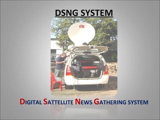
- 1. DSNG SYSTEM DIGITAL SATTELLITE NEWS GATHERING SYSTEM
- 2. WHAT IS DSNG? • Satellite news gathering (SNG) is the use of mobile communications equipment for the purpose of worldwide news-casting. Mobile units are usually vans equipped with advanced, two-way audio and video transmitters and receivers, using dish antennas that can be aimed at geostationary satellites.
- 3. Cont…. • A modern DSNG van is a sophisticated affair, capable of deployment practically anywhere in the civilized world. Signals are beamed between a geostationary satellite and the van, and between the satellite and a control room run by a broadcast station or network.
- 4. TYPES OF DSNG IN AIR NETWORK • MOBILE DSNG SYSTEM Equipments are mounted within a vehicle. • FLYAWAY DSNG SYSTEM Equipments are mounted within carry away suitcases.
- 5. LEFT UPCON- DIGITAL DIGITAL SSPA ENCODER VERTER Audio (1+1) MODULATOR (1+1) 100 W RIGHT (1+1) (1+1) (Stereo) 1.2 M from OB spot LEFT Dish Analog Antenna Audio DIGITAL Power LNBC RECEIVER (Stereo) Divider (1+1) RIGHT RIGHT Analog DIGITAL LNBC RECEIVER Audio (1+1) LEFT (Stereo) UPLINKING SET UP RECEIVE/ HUB STATION
- 6. TYPICAL MOBILE DSNG SYSTEM LOOKS LIKE
- 7. Lay out of Mobile DSNG System
- 8. TYPICAL FLYAWAY DSNG SYSTEM LOOKS LIKE
- 10. Lay out of Fly Away DSNG System
- 11. COMPONENTS OF DSNG SYSTEM • MOBILE DSNG OUTDOOR UNIT : EASILY DEPLOYABLE 1.2M ANTENNA UNIT MOUNTED ON TOP OF THE VEHICLE ALONG WITH ACCESSORIES LIKE LNBC
- 12. Cont… • INDOOR UNITS : – BASEBAND UNITS LIKE ENCODER,MODULATOR. – UPCOVERTERS,SSPA – UPS, PETROL GENERATOR.
- 13. DESIGN CONSIDERATION • Weight consideration. • Link Budget calculation.
- 14. 1. LINK BUDGET CALCULATIONS 1. Antenna Gain : G = Gain of Antenna D = Diameter of Antenna D = Wave length = = Efficiency (usually 0.5 to 0.65) The gain if the antenna under consideration = 37 dBi.
- 15. LINK BUDGET CALCULATIONS Cont…. 2. Transmit Station EIRP: 10 Log (Pt x Gt) Pt = Out put Power of SSPA/HPA in Watts. (Say : 10Watts = 10 dBw) Gt = Gain of Antenna ( 37 dBi) EIRP = 10 dBw + 37 dB = 47 dBw
- 16. LINK BUDGET CALCULATIONS Cont…. 3. Flux density at Satellite Antenna Input : = EIRP -162.2 (47 - 162.2 = 115.2 dBw/M2) 3. Path Loss : Lp = Path Loss d = Distance between uplink site & Satellite (approx 36,000,000 meters) ( = Wave length In our case it is about 200 dB at 6 GHz
- 17. LINK BUDGET CALCULATIONS Cont…. • C/No (uplink) = EIRP + G/T(sat) + Lp – k = 47 + (-2) + (-200) – (- 228.6) = 73.6 dB-Hz • EIRP(downlink) = Sat. flux density(operating) + (Sat. EIRP Saturated – O/P Back-off) + (S.F.D. - I/P Back-off) = -115.2 + (38 – 4) - (- 85 – 6.5) = 10.3 dBw
- 18. LINK BUDGET CALCULATIONS Cont…. 1. Down Link Path Loss : (In our case it is about 196 dB at 4 GHz) • Receive G/T (6 m antenna) = 25.5 dB/°K • C/No (downlink) = EIRP + G/T(CES) + Lp – k = 10.3 + 25.5 – 196 + 228.6 = 68.4 dB-Hz 7. Eb/No. = C/No – 10 Log (Data Rate) [256kbps] = 68.4 – 54.1 = 14.3 dB.
- 19. DA-20 OFFSET ANTENNA BLOCK DAIGRAM DSNG MOTORIZEDFLYAWAY ANTENNA PSU WITH DAUL FEED 1.2 mts. z GIGASAT EMERGENCY STOP GH ANTENNA GIGASAT .65 -6 CONTROLER 8 5. LNA AES/EBU GIGASAT STC 100 ANTENNA PSU 3.4 - 4.2 GHz ( - 80 dBm) LEFT ISO UP CONVERTOR C-BAND I/P AC 100-240V L MPEG I GIGASAT SOLID STATE POWER AMP. ENCODER MODEM O/P AC 100-240V PAD L-II - 15 dBm - 22 dBm CODAN DAC 700 DMD 20 UCU 60 120 W 15V DC O/P COMSTREAM RADYNE C BAND C - BAND 40 dBm 70 ± 18 MHz R 6.0 GHz L WAVE GUIDE CO-AXIAL CABLE CO-AXIAL CABLE WAVE GUIDE PAD ENCODER MODEM UCU 60 120 W DMD 20 RIGHT DAC 700 DATA C BAND C - BAND COMSTREAM CABLE RADYNE R MODEM CO-AXIAL CABLE WAVE GUIDE CO-AXIAL CABLE 70 MHz ALARM CABLE SWITCH. CO-AXIAL CABLE CO-AXIAL CABLE ALARM CABLE ALARM CABLE DUMMY ALARM CABLE ALARM CABLE SPLITER ALARM CABLE AES/EBU SPLITER LOAD UP CONVERTOR RF SWITCH SWITCH. CO-AXIAL CABLE WAVE GUIDE MODEM, UPCONVERTOR & SSPA RF SWITCH CHANGE OVER SWITCH CHANGE OVER SIGNAL 7812 7812 +12 V CABLE +12 V CABLE MAINTENANCE & COMMAND SETUP LEFT CO-AXIAL CABLE CO-AXIAL ABR 202A CABLE DAUL LNBC UNIT LAB TOP SPLITER 1:4 CO-AXIAL CABLE ANALOG AUDIO LNBC RIGHT - 40 dBm USB CABLE 2 USB CABLE SWITCH LNBC 1 LEFT ABR #2 SPLITER SPLITER ABR#1 ABR 202A MOXA MOXA CO-AXIAL CABLE LNBC RIGHT CO-AXIAL SPECTRUM CO-AXIAL CABLE CABLE ANALYZER COM 13 COM 12 COM 11 COM 10 COM 9 COM 8 COM 7 COM 6 LNBC REDUNDANCY CONTRLLER DC MONITOR PCB LNA PSU
- 20. SUBSYTEMS OF DSNG DSNG ANTENNA: Gigasat make Features: – Carbon Fiber make antenna . Weight is less than 90Kg – High efficiency offset feed design providing maximum gain – 37dBi – Antenna can be stowed. – STC-100 antenna controller enables antenna to acquire and track satellites. – Manual and motorized operation of all the three antenna motors.
- 21. SUBSYTEMS OF DSNG Cont… Antenna Controller: • STC 100 is a comprehensive controller available in 1RU providing all facilities including – Stow/Deploy – Jog Control – Auto positioning – GPS Receiver – Flux Gate Compass – Store/Recall Memory. • Communication between STC-100 and Antenna is through an RS485 cross-site connection to the Local Antenna Control unit situated in the antenna cowl.
- 22. Antenna Controller Interface diagram:
- 23. SUBSYTEMS OF DSNG Cont… 120W SSPA. CODAN Make Features: – 120Watts SSPA – 5.85Mhz to 6.425Mhz frequency range – Third order intermodulation Products is better than -25 dbc for 3dB Back-off. – 1+1 hot standby configuration. – 65dB gain – Innovative RF Power Combining technology, the latest GaAs FET devices & Surface – mounted technology are used in this SSPA
- 24. SUBSYTEMS OF DSNG Cont… C-Band Upconverter : Gigasat Make Features: • IF to C-Band Upconverter • Output power : +9dBm (max.) • Gain adjustments : >40dB in 0.5dBsteps • Two stage Upconversion i) from 70MHZ to L-Band ii) from L-Band to C-Band • RF flatness across the band ±1dB max
- 25. SUBSYTEMS OF DSNG Cont… IF Modulator: Radyne Comstream Make DMD20L • Modem provides the operation of different parameters such as variable data rates, FEC code rate, modulation type, IF frequencies, interface type can be readily set & changed at the front panel. • This allow the remote control from computer using RS232. • This modem contains a selectable RS232 or RS485 asynchronous Com Port for Earth Station – to – Earth Station communications. The baud rate & protocol can be selected from the front panel.
- 26. SUBSYTEMS OF DSNG Cont… IF Modulator: Radyne Comstream Make DMD20L Features: – IF Frequency Range 52MHZ to 88MHZ – Transmit Power: -5dBm to -25dBm – Supports Data Rates: 64kbps to 256 kbps – Supports QPSK and BPSK – FEC – Viterbi ½ – Supports monitoring and Controlling
- 27. SUBSYTEMS OF DSNG Cont… Encoder: Radyne Comstream DAC700 Features: • Digital Audio Codec • ISO MPEG I Layer-II Compression • Supports Data Rates: 64kbps to 256 kbps • Accepts Analog and Digital AES/EBU input • Supports monitoring and Controlling
- 28. SUBSYTEMS OF DSNG Cont… Digital Satellite Receiver Radyne Comstream ABR202A
- 29. SUBSYTEMS OF DSNG Cont… REDUNDANCY CONTROLLER UNIT, RFS - 60 • RFS – 60, Make GIGASAT is used to control 3 switches: One switch for encoders / modulators, one switch for the up converters and one wave guide switch for the amplifier. • The front of the controller has LEDs that display the status of each pair of equipment. • In normal use the switches are set in automatic position. • For any failure the unit will automatically switch away from the faulty peace of equipment. • If both chains of equipment are normal either chain can be selected.
- 30. SUBSYTEMS OF DSNG Cont… • 5KVA Petrol generator
- 31. SUBSYTEMS OF DSNG Cont… Hydraulic Jack System
- 32. THANK YOU