2. Introduction
• An accurate determination ,recording and
transfer of jaw relation records from
patients to the articulator is essential
for the restoration of
• function,
• facial appearance
• and maintenance of patients oral health.
4. • Maxilla is a part of the cranium and
is a fixed entity.
• When the teeth of both jaws come in
contact, maxilla becomes related to
the mandible so that entire
craniomaxillary complex is articulated
with a moving bone, which is the
mandible.
5. • The upper jaw in the human skull is
positioned uniquely to the lower jaw. This
position is different for every person.
• The relationship of the maxilla to the
temporomandibular joint is not the same in
all persons i.e., the anatomy of maxilla
and the temporomandibular joint varies
from persons to persons.
• This is the logic behind recording
orientation jaw relationship
6. • The opening movement to bring the jaw
from occlusal to rest position is almost a
pure hinge movement.
• Here the mandible moves on an arc of a
circle with a definite radius from the
temporomandibular joint. This path of the
condyle is determined by the curvature of
the condylar head and the curvature of
glenoid fossa.
7.
8. Since the radius is not constant for all
the patients, it has to be determined for
every individual patient, i.e., the relation
of maxilla to the opening and closing axis
has to be determined.
9. Orientation Jaw Relation
• They are those that orient the
mandible to the cranium in such a way
that, when the mandible is kept in its
most posterior unstrained position,
the mandible can rotate in a sagittal
plane around an imaginary transverse
axis passing through or near the
condyles. GPT -8
• The axis can be located when the
mandible is in its most posterior
unstrained position by means of a
10. The relationship of the maxilla to the
cranium in three planes viz:
anteroposterior, lateral and vertical is
called the orientation jaw relation.
11. According to Boucher
This is a relationship between the
jaws and the axis of movement,
not an anatomic relationship between
jaws and TMJ,
except to the extent that the axis
of movement might happen to be near
TMJ.
12. Hinge axis
• GPT defines hinge axis as an
imaginary line passing through the
two mandibular condyles around which
the mandible rotates without
translatory movement.
• Gnathological society defines it as
imaginary line connecting the center
13. Terminal hinge axis
• When the condyles are in their most
superior position in the articular fossa
and the mouth is purely rotated open
, the axis around which movement
occurs is called as Terminal hinge
axis.
14. • Hinge axis is a horizontal axis around
which the condyles rotate during
opening and closing movement up to a
range of
• Posselt (1952) 19-25 mm
• Ulrich (1896) about 20mm
• Campion (1905)10-20 mm
• Fischer (1935)20mm and
15. • Pure rotation of condyles takes place
in the first 10-13 degree arc of
mandibular opening and closing or
during the initial mouth opening of
15-20 mm.
• Later the condyles and disc translates
along slopes of articular fossa. This
movement is a combination of rotation
and translation.
16.
17. • Graphic records of mandibular
movements and radiographic
investigations of the TMJ have
repeatedly shown that this assumption
is well founded, and that in normal
subjects and for small opening
movements the horizontal axis of
rotation does in fact pass through the
condyles.
18. • It is true that in wider opening
movements – the axis becomes
progressively displaced downwards.
This is of anatomic interest rather
than prosthetic interest.
• In restorative and prosthetic
treatment we are concerned with
relations between teeth only when
they are in occlusion or at most
slightly separated.
19. Clinical Use Of Terminal Hinge
Axis
• The location of the transverse hinge axis
serves only to orientate the maxilla and to
record the static starting point for
functional mandibular movements. It does
not record centric relation or condylar
movements.
• Allows the transfer of the opening axis of
jaws to the articulator so that occlusion
would be on the same arc of closure as in
20. • The hinge axis recording is required
to check the accuracy of two centric
records.
• Helps in proper positioning of the
casts in relation to inter condylar
shaft.
• Vertical dimension of occlusion can be
altered on the articulator.
21. Like centric relation ,hinge axis is
• Stable
• Learnable
• Recordable
• Reproducible and
• Repeatable
Therefore it is used as an important
reference in mounting casts in the
articulator, so that the opening axis of the
articulator coincides with the terminal hinge
axis of the patient.
22. Controversy
There has been a considerable debate
about whether:
• A hinge axis exists
• Hinge axis can be accurately located
• There is only one hinge axis
• Is it clinically useful to locate the
axis
• An arbitrary point can be
satisfactorily substituted for a
kinematic axis
24. Study conducted by L. E.
Kurth & I. K. Feinstein (1951)
With the aid of an articulator &
working model , they demonstrated that
more than one point may serve as hinge
axis.
They concluded that infinite number of
points exist which may serve as hinge
points. It is unlikely to locate the
hinge axis accurately .
25. Study conducted by Robert G
Scholl Horn (1957)
He recorded the arbitrary center & true
hinge axis in 70 dental students.
He concluded that arbitrary axis of rotation
which is 13mm ant. to the posterior margin
of the tragus on tragal canthus line lies
close to an average determined axis.
In 95% of subjects Kinematic center lies
within 5mm radius , which is considered to
be within normal limits.
So determining kinematic center is not
necessary.
26. Study was conducted by
Richard L Christiansen (1959)
He mounted the maxillary casts arbitrarily
& with face bow records & studied the
errors in occlusion.
He concluded that it is advantageous to
simulate on the articulator the anatomic
relationships of residual ridges to the
condyles for more harmoniously occluding
27. Study conducted by T. D
Foster in 1959
He stated that permanent study casts
would be of more value if they are
mounted in correct relationship to the
FH plane particularly in facial
deformity involving the jaws.
28. Study was conducted by Arne
Lauritzen & George H. Bodner in
1961.
They marked true hinge axis &
arbitrary hinge axis by 3 methods
.They concluded that in 67% of
cases the true hinge axis was 5 to 13
mm away from the arbitrarily located
hinge axis points.
29. Study was conducted by Vincent R.
Trappazzan , Jhon B.Lazzari in
1961.
They conducted the study on 14
subjects .
They concluded that in 57.2% of the
subjects, more than one hinge axis
point was located on either one or
both sides.
42.8% of the subjects showed single
hinge axis point on left & right side
30. Study was conducted by Arthur
F. Aull in 1963.
• He concluded that the horizontal axis
is a hypothetical line.
• Terminal hinge position is most
posterior position.
• Arbitrary location fails to satisfy the
requirements.
• Do not support the split axis theory.
• No evidence found to believe that
there is more than one hinge location.
31. Study was conducted by Vincent R.
Trapazzano & John B. Lazzari in
1967.
• They concluded that the patient
should be relaxed & two operators are
required for location.
• Because of the presence of multiple
hinge axis points, increasing or
decreasing of the vertical dimension
on the articulator needs new inter
occlusal record.
32. Study was conducted by Virgillo
Ferrario, Chairello Sforza,
Graziano Serrao & Johannes H.
Schmitz in 2002
• They assessed reliability of the face bow
by comparing the values with those
obtained by computerized non invasive
instrument.
• They concluded that face bow reliably
reproduced the spatial orientation of the
occlusal plane relative to the true
34. Group 1
Absolute location of hinge axis
McCollum(1939)
There is a definite transverse
axis & should be located accurately.
35. Group 2
Arbitrary location of hinge axis
• Craddock & Simmons(1952)
• Believe that arbitrary location of hinge
axis is reliable, even though accurate
location is valuable.
Craddock & Symons stated that – The
search for the axis is troublesome ,
more of academic interest as it will
never be found more than few
millimeters distant from the true center
of the condylar rotations .
36. Group 3
Non believers in transverse hinge axis
location.
• Beck(1959)
• It is impossible to locate hinge axis
with accuracy.
• More theoretical than practical.
• Cannot be reproduced by an
articulator simulating one axis
therefore, an arbitrary axis
37. Group 4 Split axis rotation
• Slavens(1961)
• Believe that the condyles rotate
independent of each other.
This group believes there are two axis
of rotation (one in each condyle) and
they parallel each other.
JPD 9, 936, 1959
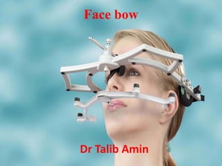
38. Face bow
The face bow is a caliper like device
that is used to record the relationship
of the jaws to the temporomandibular
joints or the opening axis of the jaws
and to orient the casts in the same
relationship to the opening axis of the
articulator.
Boucher 11th edition
39. Face bow is a caliper like device
used to record the relationship of
maxilla to the temporomandibular
joint.
Heartwell
40. Caliper like instrument used to record
the spatial relationship of the
maxillary arch to some anatomic
reference point or points and then
transfer this relationship to an
articulator; it orients the dental cast
in the same relationship to the
opening axis of the articulator.
GPT-8
42. Bonwill, (1860) determined the distance
from the center of each condyle to the
median incisal point and the lower teeth as
10cm. He used this standard for mounting
his casts in the articulator.
Disadvantage
He did not mention at what level below
43. • Balkwill (1866) demonstrated an
apparatus with which he could measure the
angle formed by the occlusal plane of the
teeth and a plane passing through the lines
extending from the condyles to the incisal
line of the lower teeth. This angle varied
from 22-30°.
• He devised methods that were
improvement on those proposed by
44. • Hayes (1880) introduced first example
of functional face bow like device
intended for locating the position of the
casts correctly in the articulator. He
named the device as articulating
caliper
45. • According to Prothero , Thomas L.
Gilmer was the first to suggest the
principle of a face bow in a paper
presented at a meeting of the Illinois
State Dental Society in 1882.
46. • Walker (1890) invented the clinometer
a new type of instrument used for
determining position of the lower cast
in relation to the condylar mechanism,
better than with all the previous
apparatus.
Disadvantage
Bulky exceedingly complicated
47. • In 1894 George K Bagby fabricated
a device that determined the distance
from the midline of the anterior
occlusal rims to one of the condyles.
49. • George B. Snow (1899)
Invented a device which became
prototype for modern face bow.
50. Since the introduction of Snow's
apparatus, no fundamental changes
have been made in the face bow
design.
Snow determined the position of
the casts in the articulator not
only in regard to distance of the
mid incisal point from the condyles
but also the other points of the
occlusal plane were given the
51. • The term, “face bow,” probably evolved
from a statement by A.D. Grit man, who
described the “implement devised by
Prof. Snow. . .as a bow of metal (that)
reaches around the face. . .”
• It first appeared in the literature in a
description for its use by Grit man and
Snow in the American Textbook of
Prosthetic Dentistry (edition 2),
1900.
52. Dalbey (1914)
Introduced the use of ear type of
face bow but it was not until late
60's the ear type did gain
popularity.
53. Uses of face bow
Face bow record is used….
• Balanced occlusion in CD
• Class I & II cases
– Open anterior bite or end to end
relationship
– Single restoration on II molar not for
premolar and I molar
– Segmental restoration
– Anterior restoration – primary guidance
factor in excursive movement
– Restoration of entire quadrant
• Diagnostic purposes and Treatment planning
54. Articulators that do not offer
possibility to use facebows are more
like model holders
55. Parts of face bow
• U-shaped frame
• Condylar rods or earpiece.
• Bite fork
• Locking device
• Third reference point.
56. U-shaped frame
It forms the main frame of the face
bow.
All other components are attached to
this frame.
It extends from the region of TMJ on
one side to the other side without
contacting the face.
57. Condylar Rods
Two small metallic rods on either side
of the free end of the U shaped
frame that contact the skin over the
TMJ.
They are used to locate the hinge
axis and transfer it to the
articulator.
Some face bows have ear piece that
fit into the external auditory meatus
58. Bite fork
“U” shaped plate, which is attached to the
occlusal rims, while recording the orientation
relation. It is attached to the frame with the
help of a rod called the stem.
59. Locking device.
This part of the face bow helps to
fix the bite fork to the U-shaped
frame firmly after recording the
orientation jaw relation.
60. Third reference point
It is used to orient the face bow
assembly to a anatomical reference
point on the face along with the two
condylar reference points. It varies in
the different face bows, example
orbital pointer-orbitale, Nose piece –
Nasion etc.
62. Arbitrary Face bow
• The hinge axis is approximately located in
this type of face bow.
• It is commonly used for complete denture
construction.
• This type of face bows generally locate
the true Hinge axis within a range of 5
mm.
63. • Uses arbitrary or approximate points
on the face as the posterior points
and condylar rods are positioned on
these point.
• As the located hinge axis is
arbitrary, occlusal discrepancies
produced in the dentures should be
corrected by minor occlusal
adjustments during insertion.
64. Fascia type
• The fascia type of face bow
utilizes approximate points on
the skin over the
temporomandibular region as
the posterior reference points.
• These points are located by
measuring from certain
anatomical landmarks on the
face.
65. Disadvantage
As the face bow is placed on the
skin which is movable there is a
tendency for the condylar rods to
displace .
Also requires an assistant to hold
the face bow in place.
66. Ear piece type
• It uses the external auditory meatus
as an arbitrary reference point which
is aligned with ear pieces similar to
those on a stethoscope.
• Accurate relationship for most
diagnostic and restorative procedures.
67. Advantage
• Simple to use.
• Do not require measurements on face
• As accurate as other face bows.
• It provides an average anatomic
dimension between the external
auditory meatus and horizontal axis of
mandible
68. Disadvantage
• Regardless of which arbitrary position
is chosen an error of 0.2 mm from
the axis can be expected.
• When coupled with the use of a thick
inter occlusal record made at an
increased vertical dimension. This
factor can lead to considerable
inaccuracy .
69. Spring bow (Hanau’s face bow)
• It is an earpiece face bow made of
spring steel and simply springs open
and close to various head widths.
• Most commonly used face bow.
• This instrument is designed to orient
the occlusal plane to the Frankfort
horizontal plane by means for a third
point of reference
70. Advantages :
• The one piece design of bow
eliminates the moving parts and
maintenance problems encountered
with other models.
• Easy and efficient to use.
• Sterilazable parts.
• Direct/indirect mounting capability.
Disadvantage :
71. Twirl bow
• It is an earpiece type of face bow
• Allows the maxillary arch to be
transferred to the articulator without
physically attaching the face-bow to
the articulator
• Relates the maxillary arch to FH
plane
72. Slidematic face bow
• Type of ear piece Face bow.
• Used with Denar articulator.
• It has an electronic device that gives
reading denoting one half of the inter
condylar distance.
73. Whip mix face bow
• Ear piece type of face bow
• It has a built in hinge axis locator.
• Automatically locates the hinge axis
when the ear pieces are placed in the
external auditory meatus
• Has a nasion relator assembly with a
plastic nose piece
74. KINEMATIC FACE BOW:
ACTUAL VALUE/ HINGE AXIS
• It is used to determine and locate the
exact hinge axis points.
• Hinge axis of the mandible can be
determined by a clutch i.e., a
segmented impression tray like device
attached onto the mandibular teeth
with a suitable rigid material such as
impression plaster.
75. Indication :
• When it is critical to precisely
reproduce the exact opening and
closing movement of the patient to
the articulator.
Draw backs :
• Extensive chair side.
• Expensive
• Rarely indicated for routine
articulators with prosthodontic
procedures.
76. The Plane of orientation
• The maxillary cast in the articulator is
the baseline from which all occlusal
relationships start.
• Therefore it should be positioned in
space by identifying three points
• Two points are located posterior to the
maxillae and one point located anterior
to it.
• The posterior points are referred to as
the posterior points of reference and
the anterior one is known as the anterior
77. The spatial plane formed by
joining the anterior and posterior
reference points is called plane of
orientation.
78. Prior to aligning the face bow on
the face, the posterior reference
points and the anterior reference
point must be located and marked.
79. Posterior reference points
The position of the terminal hinge
axis on either side of the face is
generally taken as the posterior
reference points.
80. Beyron point
13mm anterior to the posterior
margin of the tragus of the ear on a
line from the center of tragus
extending to the corner of the eye.
81. Bergstrom point:
10mm anterior to the center of the
spherical insert for the external
auditory meatus and 7mm below the
Frankfort horizontal plane.
82. Bergstrom point is found to be
most frequently closest to the
hinge axis.
Beyron point is the next most
accurate posterior point of
reference.
83. Gysi point
• 13mm in front of the most upper part
of the external auditory meatus on a
line passing to the outer canthus of
the eye.
• This method was proposed by Gysi,
Hanau, Snow and Gilmer and is the
most common point used today.
84. Other posterior reference
points
• 13 mm in front of anterior margin of
meatus : 40 % accuracy
• 13 mm from foot of tragus to canthus
with 33% accuracy
• Ear axis 75.5% accurate
85. Why Anterior Point of
Reference?
• Anterior point of the triangular spatial
plane determines which plane in the head
will become the plane of reference when
the prosthesis is being fabricated.
• When three points are used the position
can be repeated
• To visualize the anterior teeth and their
occlusion in the articulator in same frame
of reference that would be used when
86. Orbitale
• In the skull, orbitale is the lowest
point of the infra orbital rim.
• On a patient it can be palpated
through the overlying tissue and the
skin.
• One orbitale and the two posterior
points that determine the horizontal
axis of rotation will define the axis
orbital plane.
87.
88. Advantage
• It is easy to locate and mark .
• The concept is easy to teach and
understand.
Disadvantage
• Relating the maxillae to the axis orbital
plane will slightly lower the maxillary cast
anteriorly from the position that would
be established if the Frankfort horizontal
plane were used.
89. Nasion minus 23mm
• Deepest part of the midline depression
just below the level of the eyebrows.
SICHER
• The nasion guide, or positioner, of the
face bow fits into this depression,
designed to be used with whip mix
articulator
• This guide can be moved in and out, but
not up and down, from its attachment.
90. • The cross bar (u-shaped frame) is
located 23mm below the midpoint of
nasion pointer.
• When the face bow is positioned
anteriorly by the nasion guide, the cross
bar will be in the approximate region of
orbitale.
• The face bow cross bar and not the
nasion guide is the actual anterior
reference point locator
91.
92.
93. Ala of the nose
• The right or left ala is marked on
the patient and the anterior
reference pointer of the face-
bow is set.
• This method uses the Campers
Plane as the plane of orientation
96. 43 mm superior from lower
border of upper lip
• This plane represents Denar reference
plane
• Denar face bow uses this reference
point
97. Face bow transfer
• Face bows that can be utilized with Hanau
articulator
Fascia
Ear piece
Twirl bow
Spring bow
Kinematic
• Face bows that can be utilized with Whip mix
articulator
Quick mount ear piece
Kinematic
• Face bows that can be utilized with Denar
articulator
Fascia
Ear piece
108. Face bow assembly along with
bite fork is removed from the
mouth and positioned in the
articulator
109. How to take a face bow record
using arbitrary face bow
5 min Video
110. KINEMATIC METHOD OF
LOCATING HINGE AXIS
Fabrication of the clutch.
Attach clutch tray to lower teeth.
Assemble the hinge axis locator.
Attach the side arms to the cross bar in
mounting column.
Attach the assembled hinge axis locator to the
Stem of the clutch tray.
Mark approximate center of condyle on the
subject`s face.
Adjust the hinge axis locator.
Place the graph paper .
Location of the hinge axis points.
111.
112.
113. OTHER METHODS OF RECORDING
HINGE AXIS
• Pantograph– two face bows, one holds
six recording tables attached to the
mandible & other with 6 styluses
attached to the maxillae.
• Transograph.
• Stereograph
• Computerized Axiograph
114. Conclusion
• Failure to use the face bow leads to error
in occlusion.
• Hinge axis is a component of every
masticatory movement of the mandible and
therefore cannot be disregarded and this
hinge axis should be accurately captured
and transferred to the articulator. So it
becomes a fine representative of the
patient and biologically acceptable
restoration is possible.
• Whatever may be controversy reasoned by
in the use of face bow but it should form
115. References
• Boucher’S Prosthodontic Rx for edentulous
patient 9th edition.
• Syllabus of complete dentures by Charles M.
Heartwell 4th edition 5th edition.
• Essentials of complete Denture
Prosthodontics by Sheldon Winkler-2nd
edition.
• Fundamentals of fixed Prosthodontics by
Schillingburg 3rd edition.
• Management of Temporomandibular
Disorders & Occlusion 5th edition. Jeffrey
.P.Okeson.
• Evaluation, diagnosis, and treatment of
occlusal Problems, Peter E Dawson
• Prosthodontic Rx for edentulous patients by
Zarb Bolender 12th edition.
• Hobo|Eiji Ichida |Lily .T .Garcia-
116. The hinge axis of the mandible Kurth & Feinstein J.P.D:
1951:327
Recording & Transferring the mandibular axis by
Robert B. Sloane J.P.D. 1952:173.
Evaluation of face bow by Craddock & Symmons
J.P.D:1952:633.
The face bow,it’s Significance & Application by Thure
Brandrup-Wognsen J.P.D.:1953:618.
A study of the arbitrary center &the kinematic center of
rotation for face bow mounting by R.G. Schallhorn
J.P.D:1957.
Hinge axis registration on articulators Borgh & Posselt
J.P.D 1958
Rationale of face bow is maxillary east mounting by
Richard L. Christiansen J.P.D:1959:388.
A clinical evaluation of the Arcon concept of articulator
Heinz O.Beck J.P.D 1959
The use of face bow is making permanent study casts by
T.D.Foster J.D.P : 1959 :717
Hinge axis location on an experimental basis Lauritzen &
117. The anterior point of reference by Noel.D.Wilkie J.D.P
1979:41:5:488
A study of transverse axis Arthur F. Aull J.P.D;1963:469
The physiology of the terminal rotational position of the condyles in
the TMJ J.P.D: 1967:122
The need to use an arbitrary face bow when remounting complete
dentures with Intercellular records by Keki.R.Kotwal in J.D.P.
1979:224
Discrepancies between arbitrary & true hinge axis by F.M. Walker a
J.D.P:1980:43:279.
Studies on validity of terminal hinge axis C.C.Beard, J.A.Clayton
J.P.D: 1981:185
Clinical evaluation of methods used in locating the mandibular hinge
axis by Mahmoud Khamics Abdel Razek J.P.D: 1981:369
The hinge axis evaluation of current arbitrary determination
methods & proposal for new recording method J.P.D :1989
Re-evaluation of axis-orbital plane & the use of orbitale in a face
bow transfer record by Jhon H.Pitchford J.P.D.:1991:66:347.
Three dimensional assessment of the reliability of a postural face
bow transfer by Virgillo Ferrario,Chairello Sforza,Graziano
Serrao,& Johannes H. schmitz J.P.D.2002:87:210.