1. Seismic design and assessment of
Seismic design and assessment of
Masonry Structures
Masonry Structures
Lesson 10
October 2004
Masonry Structures, lesson 10 slide 1
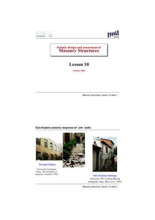
Out-of-plane seismic response of urm walls
Parapet failure
(Newcastle Earthquake
Study, The Institution of
Engineers, Australia, 1990)
Out-of-plane damage
(from the 1997 Umbria-Marche
earthquake, Italy, Blasi et al., 1999).
Masonry Structures, lesson 10 slide 2
2. Out-of-plane seismic response of urm walls
Global and partial
overturning mechanisms of
façade walls
Masonry Structures, lesson 10 slide 3
Out-of-plane collapse followed by global collapse
Tests performed
at Ismes,
Bergamo,
(Benedetti et al.
1996)
Masonry Structures, lesson 10 slide 4
3. Out-of-plane seismic response of urm walls
Seismic Load Path for Unreinforced Masonry Buildings
Floor diaphragm response Shaking
amplifies accelerations and motion
transmits load to out-of-
plane walls
Parapet wall
In-plane shear walls
response filters the
ground motion and
transmits to floor Earthquake Excitation at
diaphragms footings
Out-of-plane wall
(Doherty 2000,adapted after Priestley)
Masonry Structures, lesson 10 slide 5
Out-of-plane seismic response of urm walls
Important issues:
-Strength of wall against out-of-plane forces and relevant
mechanisms of resistance
-Out-of-plane displacement capacity of walls
-Evaluation of out-of-plane dynamic response
-Definition of seismic demand on walls considering filtering
effect of building and diaphragms
Masonry Structures, lesson 10 slide 6
4. Out-of-plane strength of urm walls
Wall subjected to horizontal distributed loading (wind or inertia forces)
(A) (B)
Overburden
Force = O
Self weight
above crack =
W/2
∆c
One-way bending, One-way bending,
before cracking after cracking
Base reaction =
O+W
Masonry Structures, lesson 10 slide 7
Out-of-plane strength of urm walls, low vertical stress
Relastic
Force Control/Dynamic Loading (Explosive)
Un-cracked Elastic Capacity
Displacement Control Loading
Applied lateral Force, w (kN/m)
Semi-rigid Non-linear F-∆
Res(1) Relationship
Un-cracked Linear Elastic
Behaviour
Mid-height Displacement (∆) ∆instability
(Doherty 2000)
Masonry Structures, lesson 10 slide 8
5. Out-of-plane strength of urm walls, high vertical stress
Res(1) Semi-rigid nonlinear F-∆
Applied lateral Force, w (kN/m)
relationship
Relastic
Force/Dynamic
Control Loading
Displacement
Control Loading
Un-cracked Linear Elastic
Behaviour
Mid-height Displacement (∆) ∆instability
(Doherty 2000)
Masonry Structures, lesson 10 slide 9
Out-of-plane flexural strength of nonloadbering walls
Two fundamental resistance mechanisms:
tensile strength of masonry to
resist one-way and two-way
arching action
bending
Masonry Structures, lesson 10 slide 10
6. Flexural strength of nonloadbering walls
Vertical one-way flexure: already treated
Clearly, when zero or very low vertical compression is present, tensile
strength of bedjoints assume an importan role and should not be neglected.
Horizontal flexure:
Masonry Structures, lesson 10 slide 11
Horizontal flexure
Empirical relations for brick
masonry (single-wythe):
⎛ σ ⎞
f tp ' = C f jt ⎜1 + n ⎟
⎜ f jt ⎟
⎝ ⎠
for toothed failure, where fjt = tensile
stregth normal to bedjoints, C=2 for stress in
MPa;
f tp ' = 0.45 f tb + 0.55 f jt
for failure in units, where ftb = tensile
strength of unit (can be assumed as 0.1 times
the compressive strength)
Masonry Structures, lesson 10 slide 12
7. Two-way flexure (single-wythe)
Most walls are supported on three or four sides. Evaluation is difficult
because the walls are statically indeterminate and the material is anisotropic.
Wall tend to show fracture lines whose pattern depends also on geometry of
wall, degree of rotational restraint, presence of vertical compression, besides
properties of materials.
Common design/assessment methods make use of
•simplistic conservative approaches such as the crossed strip method or
•yield line and fracture line approaches
Masonry Structures, lesson 10 slide 13
Arching action
Masonry Structures, lesson 10 slide 14
8. Arching action
C = fc (1−γ )t
Resisting moment: M = C(γt − ∆0 )
8C
p= (γt − ∆0 )
h2
According to EC6 and BS: (1-γ)=0.1
2
⎛t ⎞
From which, neglecting deflection (ok for h/t < 25): p = 0.72fc ⎜ ⎟
⎝ h⎠
Masonry Structures, lesson 10 slide 15
Arching action with gap
Arch action can be 4(γt)2
g≤
activated only if L
From geometry of
similar triangles:
g 2∆g
=
2γt L − g
g(L − g) gL
∆g = ≅
4γt 4γt
8C
This can be inserted in the equation of the previous slide: p= (γt − ∆g )
h2
Masonry Structures, lesson 10 slide 16
9. Influence of movement of supports on arching action
The thrust force C can produce some displacement of the
supports.
The displacement can be treated as an equivalent gap. If the
movement is a function of the thrust force, a number of trials or
iterations may be required to determine the optimum stress
level.
Axial shortening due to compression of the wall and
corresponding deflection can be treated similarly as an
equivalent gap.
Masonry Structures, lesson 10 slide 17
Post-cracking behaviour loadbearing walls in single bending
Priestley, 1985 From moment equilibrium about O:
From moment W ⋅∆ w ⋅ h2 W ∆ W ⋅ ∆ h w ⋅ h2
equilibrium about R: H = R⋅x = + ⋅ + P⋅∆ + ⋅ = + R⋅∆
2⋅h 8 2 2 2⋅h 2 8
8
P P w= ⋅ R ⋅ (x − ∆ )
h2
H=∆W/2h H=∆W/2h
∆/2
h/2
W/2
h/2
∆ w w = ma
h
W/2
Static instability
∆
W/2 occurs when ∆=x
o
x
H=∆W/2h
P+W R
Masonry Structures, lesson 10 slide 18
10. Post-cracking behaviour in single bending: statics
Calculation of force-deflection curve: first, calculate curvature at midheight
section and the associated moment, then evaluate displacement at midheight
assuming a given curvature distribution.
Mcrack=Rt/6
fcrack
fcrack=2R/t
R
φcrack=fcrack/Et
x
x=t/6
t
w ⋅ h2 8 ⋅ M crack 5 ⋅ wcrack ⋅ h 4
M crack = crack ⇒ wcrack = ∆ crack =
8 h2 384 ⋅ E ⋅ J
Masonry Structures, lesson 10 slide 19
Post-cracking behaviour in single bending: statics
After cracking, calculation behaviour is non linear and the following
relationship are used for a given value of deformation/stress at the right edge
of the section, from which the corresponding value of x is found:
M =Rx Conservatively, it can be
assumed that displacement si
f f =2R/(3(t/2-x)) proportional to curvature at
midheight :
R φ =f/(3E(t/2-x))
φ
x ∆= ⋅ ∆ crack
x φcrack
t
At ultimate, a rectangular stress block is assumed and the corresponding
curvature is evaluated, from which the displacement at midheight.
Masonry Structures, lesson 10 slide 20
11. Post-cracking behaviour in single bending: statics
Having determined the displacement ∆ at midheight corresponding to a given
value of x, from the equation:
8
w= ⋅ R ⋅ (x − ∆ )
h2
the corresponding value of distributed horizontal force is determined, and the
nonlinear force-displacement curve is determined point by point.
Note: static instability may occur before the attainment of the ultimate stress.
The behaviour is elastic nonlinear, i.e. the wall will load and unload along
the same curve.
Masonry Structures, lesson 10 slide 21
Post-cracking behaviour in single bending: rigid block behaviour
Note: if the two halves of the cracked wall were considered as rigid blocks,
the force-displacement curve would be given by the blue line, which can be
obtained by simple equilibrium of rigid blocks.:
F0 Bi-linear F- ∆
'Semi-rigid threshold Relationship
resistance' Real semi-rigid
Non-linear F- ∆
Relationship
Applied Lateral Force
K0
∆u=∆instability
Masonry Structures, lesson 10 slide 22
12. Post-cracking behaviour in single bending: rigid block behaviour
∆
∆
Masonry Structures, lesson 10 slide 23
Out-of-plane dynamic experimental behaviour
Wall specimen 5. ACCEL
(TA)
Timber wall
1. LVP
catch
(TWD)
7. ACCEL
(TWA)
2 LVP 8. ACCEL
(MWD) (MWA)
9. ACCEL
(BWA)
3. LVDT
Stationary
(BWD)
4. INSTRON 6. ACCEL reference frame:
(TTA) Rigid connection
to strong floor
Tests performed at University of Adelaide, Australia (Doherty et al. 2000)
Masonry Structures, lesson 10 slide 24
14. Out-of-plane dynamic experimental behaviour
80% PACOIMA DAM DISPLACEMENTS
40
30
20
PGD
DISPLACEMENT (mm)
10
43.2mm
0
0.02
0.6
1.18
1.76
2.34
2.92
3.5
4.08
4.66
5.24
5.82
6.4
6.98
7.56
8.14
8.72
9.3
9.88
10.5
11
11.6
12.2
12.8
13.4
-10
-20
-30
-40
-50
TIME (s ecs )
80% PACOIMA DAM VELOCITIES
0.3
80% 0.25
PGV
0.2
VELOCITY (m/S)
0.15
0.1
Pacoima
245mm/sec
0.05
0
Dam
0.02
0.62
1.22
1.82
2.42
3.02
3.62
4.22
4.82
5.42
6.02
6.62
7.22
7.82
8.42
9.02
9.62
10.2
10.8
11.4
12
12.6
13.2
-0.05
-0.1
-0.15
TIME (s ecs )
80% PACOIMA DAM ACCELERATIONS
0.4
0.3
PGA
0.2
ACCELERATION (g)
0.1
0
0.35g
0
0.58
1.16
1.74
2.32
2.9
3.48
4.06
4.64
5.22
5.8
6.38
6.96
7.54
8.12
8.7
9.28
9.86
10.4
11
11.6
12.2
12.8
13.3
-0.1
-0.2
-0.3
-0.4
TIME (s ecs )
Masonry Structures, lesson 10 slide 27
Safety wih respect to collapse: force or displacement?
Clearly, any methodology should take into consideration the nonlinear nature of
the response.
Earlier proposal by Priestley (1985): force based assessment based on equal
energy equivalence;
Equivalent
“resistance” of a
linear response
Masonry Structures, lesson 10 slide 28
15. Design accelerations
to be compared with
“resistance”
Masonry Structures, lesson 10 slide 29
A more rigorous evaluation of the flexibility of diaphragms would be made
by an adequate dynamic global model.
(from Tena-Colunga & Abrams)
Masonry Structures, lesson 10 slide 30
16. Force-based assessment with q-factor
Eurocode 8 & Italian code approach
The effect of the seismic action may be evaluated considering a force system
proportional to the masses (concentrated or distributed) of the element; the
resultant force (Fa) on the element, is computed as:
Fa = Wa Sa / qa
Wa is the weight of the element.
qa is the behaviour factor, to be considered equal to 1 for cantilever elements
(for example chimneys and parapets fixed only at the base) equal to 2 for non-
structural walls, equal to 3 (Italian code) for structural walls which do not
exceed specified slenderness limits.
Sa is the seismic coefficient to apply at the structural or non-structural wall, that
considers dynamic interaction with the building.
Masonry Structures, lesson 10 slide 31
Force-based assessment with q-factor
a g S ⎡ 3(1 + Z/H) ⎤ a gS
Sa = ⎢ − 0.5⎥ ≥
g ⎣1 + (1 − Ta /T1 ) 2
⎦ g
agS is the design ground acceleration
Z is the height from the foundation of the centre of the mass of the element
H is the height of the structure
g is the gravity acceleration
Ta is the first period of vibration of the wall element in the considered
direction (out-of-plane), estimated also in an approximate way.
T1 is the first period of vibration of the structure in the considered direction.
Masonry Structures, lesson 10 slide 32
17. Recent trends: displacement based assessment
Griffith et al., 2000-today
F0
F0 Rigid body
Applied Lateral Force
Calculated curve
Fu FU
K1
K2 KS K0
∆2 ∆u ∆1 ∆2 ∆MAX ∆U
Mid-height Displacement
Dynamic response is estimated via an equivalent secant stiffness (K2) and an
equivalent s.d.o.f. system with suitable effective damping (5% suitable for
one-way vertical bending).
Masonry Structures, lesson 10 slide 33
Recent trends: displacement based assessment
Displacement demand must be evaluated using an elastic spectrum which
takes into account the filtering effect of the structure, e.g.(Italian code)
Ts2 ⎛ 3 (1 + Z H ) ⎞
Ts < 1.5T1 ∆ d (Ts ) = a gS ⎜ − 0.5 ⎟
4π ⎜ 1 + (1 − Ts T1 )
2 2
⎟
⎝ ⎠
1.5T1Ts ⎛ Z⎞
1.5T1 ≤ Ts < TD ∆ d (Ts ) =a g S ⎜1.9 + 2.4 ⎟
4π 2 ⎝ H⎠
1.5T1TD ⎛ Z⎞
TD ≤ Ts ∆ d (Ts ) =a gS ⎜ 1.9 + 2.4 ⎟
4π 2 ⎝ H⎠
agS is the design ground acceleration
Z is the height from the foundation of the centre of the mass of the element
H is the height of the structure
g is the gravity acceleration
Ta is the first period of vibration of the element in the considered direction, estimated also in an
approximate way.
T1 is the first period of vibration of the structure in the considered direction.
Masonry Structures, lesson 10 slide 34