1. TEST REPORT Optical Distribution System
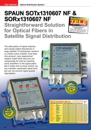
SPAUN SOTx1310607 NF &
SORx1310607 NF
Straightforward Solution SPAUN SOTx131
12-01/201
0607 NF &
1
for Optical Fibers in
SORx1310607 NF
Connect endles
s satellite and ter
rec eivers to one restrial
single rec eption
Ideally suited for point.
large apartment
blocks.
Satellite Signal Distribution
The attenuation of signal switches
and coaxial cables themselves in
large satellite TV distribution systems
is a factor every installer must take
into account. Less experienced
readers might think that one can
compensate for that by inserting
extra amplifiers in the signal paths.
But it helps only to some extent; we
can maintain reasonable signal level
but can not prevent signal quality
degradation.
0.35
TELE-satellite World www.TELE-satellite.com/...
Download this report in other languages from the Internet:
Arabic العربية www.TELE-satellite.com/TELE-satellite-1101/ara/spaun-optical.pdf
Indonesian Indonesia www.TELE-satellite.com/TELE-satellite-1101/bid/spaun-optical.pdf
Czech Česky www.TELE-satellite.com/TELE-satellite-1101/ces/spaun-optical.pdf
German Deutsch www.TELE-satellite.com/TELE-satellite-1101/deu/spaun-optical.pdf
English English www.TELE-satellite.com/TELE-satellite-1101/eng/spaun-optical.pdf
Spanish Español www.TELE-satellite.com/TELE-satellite-1101/esp/spaun-optical.pdf
Farsi فارس ي www.TELE-satellite.com/TELE-satellite-1101/far/spaun-optical.pdf
French Français www.TELE-satellite.com/TELE-satellite-1101/fra/spaun-optical.pdf
0.37
Hebrew עברית www.TELE-satellite.com/TELE-satellite-1101/heb/spaun-optical.pdf
Mandarin 中文 www.TELE-satellite.com/TELE-satellite-1101/man/spaun-optical.pdf
Dutch Nederlands www.TELE-satellite.com/TELE-satellite-1101/ned/spaun-optical.pdf
Polish Polski www.TELE-satellite.com/TELE-satellite-1101/pol/spaun-optical.pdf
Portuguese Português www.TELE-satellite.com/TELE-satellite-1101/por/spaun-optical.pdf
Romanian Românesc www.TELE-satellite.com/TELE-satellite-1101/rom/spaun-optical.pdf
Russian Русский www.TELE-satellite.com/TELE-satellite-1101/rus/spaun-optical.pdf
Turkish Türkçe www.TELE-satellite.com/TELE-satellite-1101/tur/spaun-optical.pdf
Available online starting from 3 December 2010
60 TELE-satellite — Global Digital TV Magazine — 12-01/201 — www.TELE-satellite.com
1
2. ■ Bulding
Blocks of
Hybrid Fiber-
Coaxial Distri-
bution System
The only way to keep the
C/N ratio really high is to
use low-loss switches and
transmission lines. But the
best solution that is available
today is the usage of optical
fiber cables. They can have as
low an attenuation as 0.2 dB
per kilometer and extremely
low error rates (10-10) even
at the highest bit rates.
Of course, everybody
knows that this is not elec-
trical current but a light
beam that travels along the
optical fiber cable. So, we
need to convert the electri-
cal signal into a modulated find out with our measure- The SOTx 1310607 NF has range from 47 through 2200
laser light beam. This can ments. But before the test one RF input to which we can MHz, which covers both the
be done either directly in the itself, we took a closer look at link up either the IF satellite terrestrial and the satel-
LNB – see other such test the units. As with all SPAUN signal alone or the IF satellite lite frequency range. A nice
reports elsewhere in TELE- products, their workmanship plus terrestrial signal, assum- feature is the independent
satellite - or with the help of is perfect. Also the labels put ing that we combined them adjustment of the satellite
an external converter. In the on the top cover in German together earlier (e.g. with signal levels and the terres-
latter case, we simply use a and English leave no doubt the help of a diplexer). This trial signal level in the input:
regular Quattro or Quad LNB what should be connected is possible because the input SPAUN has built into its unit
and then convert its four out- where. is designed for the frequency two 0-12 dB attenuators.
puts to light. SPAUN, the well
known German manufacturer,
has sent us their latest prod- graph 1
uct designed for this purpose
– SOTx131607 NF. They call
it optical transmitter.
At the other end of the opti-
cal fiber we need to do the
reverse operation – demodu-
lation back to an electrical
signal. SPAUN called the unit
doing this function an opti-
cal receiver and assigned
to it the model number:
SORx1310607 NF. Fine, but
do not extra modulation and
demodulation spoil C/N of the
signal? This would ruin all the
benefits introduced by low-
loss optical fiber cables. This
is exactly what we wanted to
62 TELE-satellite — Global Digital TV Magazine — 12-01/201 — www.TELE-satellite.com
1
3. to the first transmitter and
connect the second trans-
mitter with a piece of coaxial
cable. In this way, we do not
need separate power supply
units for every transmitter.
SPAUN’s PSU sold in a set is
strong enough to power up
to four transmitters assum-
ing no power for an LNB is
needed. If we need to power
a LNB, which will usually
be the case, the number is
reduced to three transmit-
ters. Nevertheless, it is a
simplification of the whole
installation.
The optical transmit-
ter also has a LED indicator
which except for signaling
the connection of power can
also inform us about a short
circuit in the LNB input. It
simply starts blinking. That’s
very intuitive.
Another electrical output
is the test signal described
as -20 dB. This is simply the
input attenuated by 20 dB
which is the light modulator
input. We can use it to check
if the RF signal is really pre-
Optical transmitters cannot the help of a switch mounted 12V/22kHz, 18V/22kHz). If sent on the transmitter input
get power supply via an opti- on the transmitter cover, we we have a signal source not and what is its level.
cal fiber cable. We need to select the proper voltage and requiring DC power, we can
connect an external 19 V DC presence of 22 kHz signal. switch it off completely. The optical output SC/APC
power supply. SPAUN adds a Thanks to that, we can use is protected with a black cover
suitable one to every SOTx either a Quattro LNB (then, The SOTx 1310607 NF has which has to be removed
1310607 NF. Electric power we simply set 12 V in all four two F type plugs connected before an optical fiber is con-
is needed not only for the signal paths) or a Quad LNB in parallel for power supply. nected. By the way, connect-
unit but also to supply the (then, we need to set each Thanks to that we can con- ing optical inputs and outputs
LNB connected to it. With path differently: 12V, 18V, nect one power supply unit is a dream for a satellite
installer. Press gently until
you feel a click and that’s it.
graph 2 What a nice difference after F
connectors!
To send “down” four sig-
nals from a Quattro LNB
we need to use four SOTx
1310607 NF transmitters.
Fortunately, it was possible
to miniaturize the receiver
much more than the trans-
mitter. The SORx 1310607
NF is a quad receiver: it has
four optical inputs and four
electrical RF outputs. In con-
trast to the transmitter, the
receiver is shipped without
a power supply, because it
is supposed to get its power
from the central distribu-
tion unit or multiswitch, like
www.TELE-satellite.com — 12-01/201 —
1 TELE-satellite — Global Digital TV Magazine 63
4. any regular LNB. A coaxial
plug called “C” at the optical
receiver acts as connector to
power; here the user is sup-
posed to connect the coaxial
cable from a central unit or
multiswitch.
In our case we did it differ-
ently: as the optical receiver
needs exactly the same DC
voltage as the transmitter,
we took one power supply
units from the transmitter
sets. The units are very ver-
satile: not only do they offer
a wide supply voltage range
(100...240V AC / 47...63 Hz)
but SPAUN also delivers a
number of exchangeable pin
adapters so you can use it
anywhere in the world.
The DC supply can be con-
nected to any of the two F
connectors. As in the trans-
mitter, they are connected in
parallel. So if the DC power is
needed for a similar device in
the neighborhood, we will use
graph 3 rather a coaxial cable than
another power supply unit.
An LED indicator shows if the
unit is powered.
The transmitter and the
receiver can be mounted on
the wall with only 2 screws.
They should not be exposed
to the open air but rather used
indoors. However, their oper-
ating temperature is pretty
wide: -20°C through +50°C.
The brochure attached to
every unit is printed in Eng-
lish and German and provides
all necessary information
along with exemplary appli-
graph 4 cation circuits.
Measurements
After getting familiar with
the units, time had come to
put all the blocks together and
see what kind of performance
they offer. SPAUN recom-
mends to supply the optical
fiber distribution system with
really strong signals: 80-83
dBµV for the satellite IF and
85 for terrestrial. The maxi-
mum value is 95 dBµV.
Steffen Kuck, SPAUN’s
Technical Manager, explained
64 TELE-satellite — Global Digital TV Magazine — 12-01/201 — www.TELE-satellite.com
1
5. ■ Steffen Kuck strongest carrier (equal to several hundreds of satel-
is SPAUN‘s SPAUN recommendation) lite receivers! The number
Technical
Manager for the everything stayed perfect of subscribers which can be
optical system (48 vs. 47 dB). SPAUN’s opti- reached with this new tech-
cal system really just trans- nology is really impressive.
ports the input signal as it is
received. At the same time, one must
to us: “Our optical system 5 dB or 10 dB lower than the remember that optical fibers
is designed for maximum system input depending on Applications do not allow DiSEqC signals
performance and as such the attenuator we used. to pass. To multiply a number
These new optical units
requires a strong input of satellites available to the
from SPAUN open a brand
signal.” But what about signal qual- end user, one must multiply
new era in large TV distribu-
ity? This can be assessed by the number of optical fibers
tion networks. Every opti-
We supplied our test unit Modulation Error Ratio in the (8 for 2 satellites, 12 for 3
cal signal on the transmitter
with a real life signal from input and in the output. We satellites and so on) as well
output can be split to 32
HotBird satellite. We con- noticed very small deteriora- as transmitters and receiv-
optical fibers and thus create
nected the transmitters with tion of signal quality. (graph ers.
enormous backbones for the
the receiver with short optical 3., graph 4.) It is almost network.
fiber cables. So, to simulate nothing. Should we have 10 SPAUN’s new optical trans-
optical splitters (or very, very or 15 dB attenuation in a long mitter system not only makes
For example, on every floor
long cables), we inserted a coax cable, the signal could installation easier but also
of a large apartment block we
10 dB optical attenuator and be already on the edge of the secures that each end-user
can have an optical receiver
later even a 15 dB attenu- reception threshold. will have a strong and perfect
with four electrical outputs
ator. As you can see in the signal available at his socket,
which in turn can be fed to
graphs (graph 1., graph 2.), But what about the analog even at the most remote
the conventional multiswitch
the receiver output was only terrestrial signals? For the corner of a big network.
and distributed further to
ENERGY Expert Opinion
DIAGRAM +
Very good workmanship
DC power “sharing” among the units
Apparent Power Excellent performance for DVB-S signals even if
below the recommended signal level (80-83 dBµV)
Very good performance for analog TV signals
Jacek Pawlowski
for the recommended high input levels (85 dBµV) TELE-satellite
Test Center
Possibility to create really large distribution Poland
networks
Active Power Possibility to send signal over a long distance
-
Mode Apparent Active Factor
Reception 17 W 6W 0.35
none
Power consumption of SORx 1310607 NF Optical Receiver meets the
TECHNICAL
specification (6W). DATA
Manufacturer SPAUN Electronic, Singen, Germany
ENERGY Fax +49 (0) 7731 – 8673-17
DIAGRAM
E-mail info@spaun.de
Model SOTx 1310607 NF & SORx 1310607 NF
Function Optical Transmitter & Optical Receiver
Apparent Power
Frequency range 47 … 2200 MHz
Optical wavelength 1310 nm
Power consumption 6 W (plus LNB power for transmitter)
Maximum supply current of the connected 400 mA
LNB
Active Power
Transmitter output power (optical) 6 dBm
Mode Apparent Active Factor
Reception 29 W 11 W 0.37
Transmitter maximum RF input 95 dBµV
Receiver maximum RF output level 100 dBµV (Terr.), 110 dBµV (SAT)
Receiver input range (optical) 0 … -12 dBm
RF and DC voltage connector typ F
Power consumption of SOTx 1310607 NF Optical Transmitter is about 11 Optical connector type SC/APC
W but only 6 W is consumed by the transmitter itself. The rest is used to
Operating temperature -20 C° ... 50 C°
supply the connected LNB.
66 TELE-satellite — Global Digital TV Magazine — 12-01/201 — www.TELE-satellite.com
1