1. 128 129TELE-audiovision International — The World‘s Largest Digital TV Trade Magazine — 03-04/2013 — www.TELE-audiovision.com www.TELE-audiovision.com — 03-04/2013 — TELE-audiovision International — 全球发行量最大的数字电视杂志
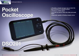
Pocket
Oscilloscope
DSO201
• Provides a simple and easy way to check the
basic functions of a satellite system
• Produces a 22kHz signal
• Can also be used to check the video and audio
signal
• Especially capable of finding complex errors
Oscilloscope for Basic Use
2. ■
130 TELE-audiovision International — The World‘s Largest Digital TV Trade Magazine — 03-04/2013 — www.TELE-audiovision.com
Oscilloscope for Basic Use
Antenna installers are some-
times confronted with problems
that they can’t solve even with a
higher-end satellite signal ana-
lyzer. The pocket oscilloscope
DSO201 provides an interesting
alternative. We tested it as a sig-
nal analyzer for satellite installa-
tions.
The DSO201 represents an open
source development of the hardware
and software. It is based on an ARM
Microcontroller that comes with the
necessary inputs and outputs. From
the outside, the DSO201 looks simi-
lar to an MP3 player; even the buttons
have the same symbols. But instead of
an output for a headphone, there’s an
input for the included oscilloscope test
probe. Aside from that, there’s also a
small slit in one corner with a metal
pin. But this is not for fastening a car-
rying strap; instead it’s an output for
the integrated signal generator. The
color screen is easy to read and at 320
x 320 pixels its resolution is sufficient-
ly high enough. A battery charger is
not included although any typical mini
USB charger can be used to charge the
DSO201.
Since with this oscilloscope we are
dealing with an Open Source design
and that the circuit board layout and
the source code are freely accessi-
ble, a variety of firmware versions
A Small Oscilloscope
Aids in Measurements
Vitor Martins Augusto
are available. All oscilloscopes with
the DSO201 label are compatible with
each other and can be operated with
different firmware versions that can be
downloaded, for example, from http://
code.google.com/p/dsonano/. After
several tests with the preinstalled
firmware, we opted to install the popu-
lar “BenF” firmware. This version was
optimized for speed and comes with
some sophistication.
But the more important question
that needs to be answered is: how do
you upload the new firmware? Short of
finding a description on how to do this,
we copied the two firmware files onto a
MicroSD card. But after ten attempts to
try and start a flash process, we knew
The DSO201 operates with
an integrated signal generator
that is capable of generating an
acceptable 22kHz signal
3. ■
■
132 133TELE-audiovision International — The World‘s Largest Digital TV Trade Magazine — 03-04/2013 — www.TELE-audiovision.com www.TELE-audiovision.com — 03-04/2013 — TELE-audiovision International — 全球发行量最大的数字电视杂志
it was time to throw in the towel and
have a look in the Internet for instruc-
tions. Finding this wasn’t exactly easy
but finally after a tutorial we under-
stood why it didn’t work using the Mi-
croSD card. The firmware is flashed via
the USB port. In order for this to work,
you need DfuSe. This turns out to be
a demo tool to update firmware that
can be downloaded for free from www.
st.com/stonline/stappl/resourceSelec-
tor/app?page=resourceSelector&doct
ype=SW_DEMO&ClassID=1734.
Next the oscilloscope must be start-
ed in Bootloader mode. This is done
by turning on the oscilloscope while
holding down the minus (-) button.
A notification identifying Bootloader
mode appears on the screen and the
DfuSe tool automatically recognizes
the oscilloscope. We recommend that
you first create a backup of the exist-
ing firmware before proceeding. To do
this select “Choose” in the “Upload Ac-
tion” field. Select a name for the file,
for example, “backup.dfu” and click
on “Upload”. Now you can upload al-
ternative firmware at your leisure. We
recommend the “DSO BenF Firmware
v3.61”. This consists of two files, “DSO
BenF APP v3.61.dfu” and “DSO BenF
LIB v3.52.dfu”. Start both of them one
after the other and then restart the
DSO201.
In comparison to a multimeter that
only shows the current voltage level,
an oscilloscope displays the voltage
over a period of time and it makes
analog and digital signal visible. With
a multimeter you can, for example,
check to see if the 14VDC power for an
LNB in horizontal polarization is avail-
able. The 22kHz signal that is used to
switch between an LNB’s low and high
band cannot be seen with a multim-
eter; it’s a square wave signal with a
frequency of 22kHz but with a varying
voltage of less than 1.0 volt. A mul-
timeter would simply continue to dis-
play 14V. An oscilloscope can make a
square wave signal visible and thereby
lets you confirm, for example, if a re-
ceiver is properly producing a 22kHz
signal.
The main feature of an oscilloscope
is its resolution. This describes the fre-
Troubleshooting:
the vertical/lowband
polarization could not
be received from Astra
19.2E. The DSO201
was used to determine
that the multiswitch
was OK
Troubleshooting continues: no
signal reached the Quadro LNB,
a clear indication that there’s a
cable failure. The cause was then
quickly identified: The “F” coupling
was completely oxidized and had
to be replaced. Astra 19.2E could
once again be received on all four
polarizations! The DSO201 came to
the rescue!
quency that the scope can measure.
Professional analyzers can perform
fast measurements with over 100MHz.
The DSO201 is promoted as having a
bandwidth of 1MHz but this is more of
a marketing value. In reality the band-
width of handheld oscilloscopes should
be reduced by a factor of ten in order
to obtain more realistic values. So how
else would you use the DSO201 in sat-
ellite applications beyond measuring
the 22kHz signal?
As previously mentioned, an os-
cilloscope measures a voltage over
a period of time. This time period is
user-settable, typically from 1µs to 1s
or even longer. This value represents
the time period on the x-axis while the
voltage is represented by the y-axis.
When the end of the x-axis is reached,
the display restarts from the begin-
ning. With analog oscilloscopes with a
CRT, the cathode beam is simply re-
turned to the left side of the screen
and starts moving once again to the
right. Without any additional configu-
ration a very confusing and fidgety
image would be displayed; the return
sweep in the x-axis usually doesn’t
occur at an ideal time for the next
graphic to be offset generated. To
solve this there’s the Trigger function.
This function only allows a new graph-
ic to be generated when the voltage
level reaches a predefined level. With
periodic swings a freeze-frame image
is created. The Trigger function offers
two parameters: the voltage limit val-
ue and the the Trigger type:
- Decreasing
- Increasing
- Single shot
- Continuous
A horizontal marker is raised or low-
ered to mark the voltage level where
the oscilloscope begins a new meas-
urement from the left side of the
screen. The DSO201 can offset the null
point above the x-axis so that signals
that exist before the Trigger point can
be made visible. In order to read the
results, a modern oscilloscope comes
with a Pause function that freezes the
current screen image. Two horizontal
and two vertical markers can then be
placed as needed on the display so
that the voltage and time period can
be read. The calculated minimum and
maximum values along with the delta
value are then displayed. The DSO201
4. 4
5
6
7
8
1
2
3
134 TELE-audiovision International — The World‘s Largest Digital TV Trade Magazine — 03-04/2013 — www.TELE-audiovision.com
has the capability to automatically
measure and display the frequency of
a periodic signal.
Our interest in the DSO201 has to
do with a big problem that can be en-
countered in a satellite antenna instal-
lation. Customers routinely complain
that they can’t receive every channel.
Many times the cause of this is faulty
supply voltage to the LNB, a defective
22kHz signal, sometimes it’s a defec-
tive tuner and very often it’s simply
the LNB that is no longer up to snuff.
Most satellite signal analyzers can’t be
used to troubleshoot these problems
especially when there are no substi-
tute receivers or LNBs.
An oscilloscope, on the other hand,
can quickly pinpoint the cause of the
problem:
• 14/18V Troublesooting: To check
and see if the LNB is getting the proper
voltage, a multimeter would be good
enough. The voltage measured at the
inner conductor should be 14VDC for
vertical polarization and 18VDC for
horizontal polarization. But with the
1. 14.1V and a straight line – the LNB
was switched to the vertical low band.
2. The tuner provides the 22kHz
signal to switch to the high band. The
DSO201 automatically displays the
signal in the upper right. The shape
of the signal is quite good indicating
that the tuner is using an optimal
signal generator.
3. Checking the tuner of a receiver.
The 22kHz signal in reality is
only 21.8kHz and the voltage
level averages 18.9V (horizontal
polarization). This is all OK to
guarantee the proper switching of the
LNB.
4. With another receiver the frequency
is 22.8kHz and for the vertical
polarization we measured 14.4V.
5. With this receiver the signal
doesn’t exactly look like a square
wave yet it’s still correctly interpreted
by our LNBs; the DSO201 also
indicates an acceptable frequency of
21.8kHz.
6. Even DiSEqC commands can be
displayed by the DSO201 but for the
most part they can’t be interpreted.
But at least you can confirm that a
signal is being sent and also arriving
at the input of the multiswitch. While
the DiSEqC command is being sent,
the 22kHz signal is momentarily
interrupted!
7. Here the DSO201 is displaying a
video line. Clearly recognizable to the
left is the black edge band and the
line synchronization pulse as well as
the black edge band on the right side.
8. Almost everyone has already seen
an audio signal on an oscilloscope.
DSO201 this voltage can not only be
measured, it can also be monitored
over a short period of time so that, for
example, any dropouts or pulses can
be made visible.
• 0/22kHz Signal: More and more
often we see older receivers or signal
analyzers that can no longer properly
switch to the high band. The question
the installer has to answer: is the tun-
er defective or is it the LNB? With the
DSO201 you can instantly determine if
the 22kHz signal is available and if it’s
of sufficient quality. In theory it should
be a square wave signal but in reality
different receivers produce very indi-
vidualized switching signals.
• DiSEqC Commands: Another prob-
lem could be faulty switching between
different satellite positions. DiSEqC
switches have a tendency to fail es-
pecially if they’re mounted on the
antenna mast. In our experience the
life span of a DiSEqC switch is about
four years before at least one input
no longer functions correctly. The
DSO201 can’t be used to interpret the
DiSEqC commands, but they can be
made visible. So, the DSO201 can be
used to confirm that the signals are
being sent and that they are reaching
the corresponding multiswitch.
5. ■
1 2
136 137TELE-audiovision International — The World‘s Largest Digital TV Trade Magazine — 03-04/2013 — www.TELE-audiovision.com www.TELE-audiovision.com — 03-04/2013 — TELE-audiovision International — 全球发行量最大的数字电视杂志
• RS-232: The DSO201 can also be
used to display the RS-232 signals,
that is, the serial interface communi-
cations. It’s not possible to log or in-
terpret these signals but you will be
able to recognize, just like with DiSEqC
commands, that data bits are being
sent or received. And with a little prac-
tice, the baud rate can be identified.
We recommend preparing an extra
adapter with which the RX and TX data
lines can be more easily probed since
it would be very hard to get to the cor-
responding pins of the interface.
• Video-Signal: The best way to
check a composite video signal is with
a TV but a picture doesn’t always make
it to the TV screen. There could be a
fault with the receiver or with the TV,
or the problem could be with the cable.
If you as an installer don’t have a sub-
stitute at hand, the DSO201 can help.
It can present the TV picture lines that
are easy to recognize based on the
blanking intervals. Not much practice
is needed to determine if a video sig-
nal is useable based on the graphic.
• Audio-Signal: Just like with the vid-
eo signal, the DSO201 can also display
the audio signal. This makes it easy to
determine if an audio signal is present
or if there’s a problem inside the re-
ceiver. A small tip: make sure the vol-
ume isn’t turned all the way down, the
mute function isn’t active or if only the
digital audio output is active…
You’ll always come across some-
thing that doesn’t work and yet with
the DSO201 oscilloscope the problem
can typically be isolated in just min-
utes. Sometimes the LNB voltage fails,
sometimes the 22kHz generator be-
comes defective. More often than not
though it’s a problem in the cabling:
the wrong cable is connected to the
multiswitch and no signal reaches the
TV room. The DSO201 can help in an
instant.
If you’re not expecting a powerful,
professional-class digital oscilloscope,
you won’t be disappointed with the
DSO201. The scope is quite small and
relatively inexpensive. It has become
a standard piece of test equipment
here in our test center; it takes up less
room than a multimeter and is a per-
fect troubleshooting tool.
1. The DSO201 is programmed with the help of the DfuSe demo application. The device is
turned on by holding down the VOL button and connected to a PC via the USB interface.
DfuSe should show “STM Device in DFU Mode” in the upper left.
2. First you should create a backup the preinstalled firmware. Click on “Choose” to name
the file and then on “Upload”. When the status line below shows “Target 00: Upload
successful!” you can safely upload alternative firmware. In an emergency you can reload
the backup.
Our test center is al-
ways busy. There are
receivers, signal analyz-
ers, TV cards, etc. that
constantly need to be
tested. Unfortunately,
you can’t get around the
fact that there will some-
times be failures. And so
I had my own little dumb
mishap: everyone knows
that you shouldn’t plug
in or unplug an LNB ca-
ble while the tuner is
turned on so as to avoid
any short circuits. But if
you’re in the middle of a
test and need to quick-
ly move a cable around,
you might be inclined to
ignore this golden rule.
Last night while I was
undergoing an extreme
satellite card test that
involved switching back
and forth between differ-
ent antennas, I wanted
to connect the motorized
antenna one more time.
I unplugged the cable
The DSO201 can easily be
used on all the different receiver
outputs to determine if a signal
is present without the need of
cables or monitors.
One Day
in the
Test Center...
and then wanted to plug
it in to the antenna when
a small spark jumped
from the center conduc-
tor to the outside shield.
This wouldn’t be the first
time that this happened
to me but at some point
in subsequent tests I no
longer had a proper sig-
nal. Of course, I thought,
the tuner had failed. But
it wasn’t that simple; I
was still able to display
transponders with Cra-
zyScan although the an-
tenna wouldn’t turn and
actually the spectrum
should have appeared
differently.
To make a long story
short, I used to DSO201
to determine that the
tuner was no longer sup-
plying the necessary
14/18V. That I was still
able to receive tran-
sponders was only be-
cause the antenna had
a twin LNB. The neces-
sary voltage was being
supplied by other satel-
lite signal analyzers that
were also connected.
That’s why it was pos-
sible to receive a sig-
nal but not possible to
switch between polari-
zations. And it’s exactly
these kinds of “failures”
where the DSO201 would
be a perfect tool to find
out what’s going on.
A useful tip: if you want
to move cables around on
a satellite PC card with-
out having to turn the PC
on and off, simply end
the TV application. This
would also turn off the
power to the tuner and a
short circuit would then
not cause any damage.