Boost PC performance: How more available memory can improve productivity
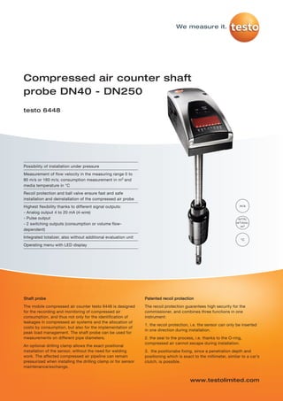
Testo - 6448 - Compressed air counter shaft probe
1. testo-6448 20.11.2012 15:13 Seite 1
We measure it.
Compressed air counter shaft
probe DN40 - DN250
testo 6448
Possibility of installation under pressure
Measurement of flow velocity in the measuring range 0 to
80 m/s or 160 m/s; consumption measurement in m3 and
media temperature in °C
Recoil protection and ball valve ensure fast and safe
installation and deinstallation of the compressed air probe
Highest flexibility thanks to different signal outputs: m/s
- Analog output 4 to 20 mA (4-wire)
- Pulse output m 3 /h;
- 2 switching outputs (consumption or volume flow- m 3 /min;
m3
dependent)
Integrated totalizer, also without additional evaluation unit
°C
Operating menu with LED display
Shaft probe Patented recoil protection
The mobile compressed air counter testo 6448 is designed The recoil protection guarantees high security for the
for the recording and monitoring of compressed air commissioner, and combines three functions in one
consumption, and thus not only for the identification of instrument:
leakages in compressed air systems and the allocation of
1. the recoil protection, i.e. the sensor can only be inserted
costs by consumption, but also for the implementation of
in one direction during installation.
peak load management. The shaft probe can be used for
measurements on different pipe diameters. 2. the seal to the process, i.e. thanks to the O-ring,
compressed air cannot escape during installation.
An optional drilling clamp allows the exact positional
installation of the sensor, without the need for welding 3. the positionabe fixing, since a penetration depth and
work. The affected compressed air pipeline can remain positioning which is exact to the millimeter, similar to a car’s
pressurized when installing the drilling clamp or for sensor clutch, is possible.
maintenance/exchange.
www.testolimited.com
2. testo-6448 20.11.2012 15:13 Seite 2
testo 6448 – Compressed air counter shaft probe DN40 - DN250 We measure it.
Technical data
Parameters
Flow velocity
Selectable units m/s
Measuring range1 0 to 80 or 160 m/s
Accuracy ±3 % of meas. value ±3 % of fsv (at room temperature)
Sensor Thermal, glass-coated ceramic sensor (calorimetric measurement procedure)
Response time 〈 0.1 sec (for damping parameter = 0), delayable via operating menu (0 to 1 sec)
(Norm) volume flow
Selectable units m3/h, m3/min, m3
Measuring range1 Maximum measuring range of volume flow is dependent on inner pipe diameter (see page 3)
Temperature
Unit °C
Measuring range 0 to +60 °C / 32 °F to +140 °F
Inputs and outputs
Analog outputs
Output type 4 to 20 mA (4-wire) freely scalable between zero and measuring range end
Load max. 500 Ω
Further outputs
Pulse output Pulse speed freely settable in 1 m3 steps
Switch output 2 switch outputs, parameterizable (consumption or volume flow-dependent, NC, NO, hysteresis, window), loadable
with max. 20 to 30 VDC or 250 mA each, switch status is displayed via 2 LEDs
Supply
Voltage supply 19 to 30 V DC
Current consumption 〈 100 mA
Connection M12 x 1 plug, loadable up to 250 mA, short-circuit-proof (synchronized), reverse-polarity-proof, overload-proof
General technical data
Design
Material housing PBT-GF 20, PC (APEC), Makrolon, V2A (1.4301), Viton
Weight 850 g
Display
Display 4-figure alphanumerical display, two operating buttons, operating menu, LED (4 x green for phys. units, 3 x yellow
for display x 1,000 or switch status)
Operation
Parameterization 2 operating buttons
Miscellaneous
Protection class IP 65/III
EMC according to guideline 89/336 EEC
Media contact V2A (1.4301), PEEK, polyester, Viton, anodized aluminium, glass-coated ceramics
Norm reference Calculation of volume flow due to manual input possibility of temperature, humidity and pressure.
Works settings: 15 °C, 1013.25 hPa, 0 %RH
Operating conditions
Humidity (sensor) rel. humidity 〈90 %RH
Operating temperature (housing) 0 to +60 °C (+32 to +140 °F)
Storage temperature -25 to +85 °C (-13 to +185 °F)
Measurement medium Compressed air, with special calibration also CO2 or N2
Process pressure PN 16 (max 16bar/232psi)
Pressure tightness/ 16 bar (max.) for DN40-DN200; 10 bar (max.) for DN250-DN300
pipe clamp
Air quality ISO 8573: recommended classes 1-4-1
1 Specifications according to DIN 2533 (+15 °C, 1013.25 hPa, 0 %RH)
3. testo-6448 20.11.2012 15:13 Seite 3
testo 6448 – Compressed air counter shaft probe DN40 - DN250 We measure it.
Technical drawings Measuring range
volume flow
according to
DIN2533
Version 80 m/s 160 m/s
DN 40 300 m3/h 600 m3/h
DN 50 500 m3/h 1000 m3/h
DN 65 940 m3/h 1880 m3/h
DN 80 1300 m3/h 2600 m3/h
DN 100 2200 m3/h 4400 m3/h
DN 125 3350 m3/h 6700 m3/h
DN 150 4975 m3/h 9950 m3/h
DN 200 8500 m3/h 17000 m3/h
DN 250 12825 m3/h 25650 m3/h
Electrical connection
5 options A B C D E
Terminal allocation
1 Supply connection 19 to 30
VDC (+)
Define in (Switch) 2 OUT 2 (analog output (4 to 20
menu (Switch) (Switch) Hno / Hnc mA) or switch output
Output 1 Hno / Hnc Hno / Hnc ImP * ImP * Fno / Fnc
Fno / Fnc Fno / Fnc or 3 Supply connection 0 V (-)
OUT 1
ImP (Pulse) 4 OUT 1 (pulse output or
switch output)
Output 2
I I Wire colours for cable 0699 3393
OUT 2 Hno / Hnc Hno / Hnc
ImP brown
Fno / Fnc Fno / Fnc
M12 socket M12 plug on Current Current (Pulse)
(Switch) (Switch) white
on cable instrument signal signal
L + (19 to blue
BN 30 VDC)
black
WH
OU
T2
testo 6448
BK
OUT
BN = brown * If menu selection ImPR
1
WH = white 0 VDC = Yes -> Pulse output
BU
BK = black If menu selection ImPR
BU = blue = No -> Switch output
(pre-selection counter)
A/C* A/D* C/B* B/D*
4. testo-6448 20.11.2012 15:13 Seite 4
testo 6448 – Compressed air counter shaft probe DN40 - DN250 We measure it.
Options / Ordering example
Order data testo 6448
AXXX configuration Ordering example
BXX Drilling clamp selection
BXX Drilling clamp selection
0981 8374/msp/A/11.2012
B00 without drilling clamp
B01 drilling clamp DN40 Order code for transmitter testo 6448 –
CXX Measurement fitting selection Compressed air counter shaft probe
B02 drilling clamp DN50
B03 drilling clamp DN65 - With transmitter incl. recoil protection
B04 drilling clamp DN80 - 80 m/s
B05 drilling clamp DN100
B06 drilling clamp DN125 - Air (compressed air)
AXXX configuration
B07 drilling clamp DN150 - Without calibration
A0 accessories only *
B08 drilling clamp DN200 - Length variant 435 mm (for DN125 to
A1 with transmitter incl.
B09 drilling clamp DN250 DN250)
recoil protection **
B10 drilling clamp DN300
AA0 80 m/s - Without drilling clamp
AA1 160 m/s
CXX Measurement fitting selection - Without measurement fitting /
AC0 Air (compressed air)
AC1 Alternative gas: nitrogen without ball valve
C00 without measurement fitting / without ball
AC2 Alternative gas: CO2 valve
AD0 factory protocol only C01 measurement fitting (incl. ball valve for -> 0555 6448 A1 AA0 AC0 AD0 AE1 B0
AD1 ISO calibration protocol m/s other meas. parameter, e.g. dewpoint C0
at 6 points transmitter testo 6740)
AD2 ISO calibration protocol m3/h C02 ball valve (DN15)
at 6 points for specific
nominal diameter
(pls. indicate diameter)
AE0 Standard length 285 mm Order code for transmitter testo 6448 –
(for DN40 to DN100) drilling clamp DN40:
AE1 Length variant 435 mm
(for DN125 to DN250)
- Accessories
- With drilling clamp DN40
- Without measurement fitting /
without ball valve
Subject to change without notice.
* If this selection is made, further configuration -> 0555 6448 A0 B01 C0
AXX is not necessary. Continue with BX.
**Further Configuration necessary! Continue
with AXX.
*** A connection cable, e.g. order no. 0699
3393 is required for operation.
www.testolimited.com