SlideShare une entreprise Scribd logo
1  sur  73
INTERNETWORKING BASICS
What Is an Internet work?
An Internet work is a collection of individual networks, connected by intermediate networking devices, that
functions as a single large network. Internetworking refers to the industry, products, and procedures that meet
the challenge of creating and administering internet works. Figure 1-1 illustrates some different kinds of
network technologies that can be interconnected by routers and other networking devices to create an internet
work.
         Figure 1 Different Network Technologies Can Be Connected to Create an Internet work


                                                  Figure 1


History of Internetworking: -

The first networks were time-sharing networks that used mainframes and attached terminals. Both IBM’s
Systems Network Architecture (SNA) and Digital’s network architecture implemented such environments.
Local-area networks (LANs) evolved around the PC revolution. LANs enabled multiple users in a relatively
small geographical area to exchange files and messages, as well as access shared resources such as file servers
and printers.
Wide-area networks (WANs) interconnect LANs with geographically dispersed users to create connectivity.
Some of the technologies used for connecting LANs include T1, T3, ATM, ISDN, ADSL, Frame Relay, radio links,
and others. New methods of connecting dispersed LANs are appearing everyday.
Today, high-speed LANs and switched internet works are becoming widely used, largely because they operate
at very high speeds and support such high-bandwidth applications as multimedia and videoconferencing.
Internetworking evolved as a solution to three key problems: isolated LANs, duplication
of resources, and a lack of network management. Isolated LANs made electronic communication between
different offices or departments impossible. Duplication of resources meant that the same hardware and
software had to be supplied to each office or department, as did separate support staff. This lack of network
management meant that no centralized method of managing and troubleshooting networks existed.


Internetworking Challenges


The Technical Zone                                                                                      Page 1
Implementing a functional internetwork is no simple task. Many challenges must be faced, especially in the
areas of connectivity, reliability, network management, and flexibility. Each area is key in establishing an
efficient and effective internetwork.
The challenge when connecting various systems is to support communication among disparate technologies.
Different sites, for example, may use different types of media operating at varying speeds, or may even include
different types of systems that need to communicate.
Because companies rely heavily on data communication, internetworks must provide a certain level of
reliability. This is an unpredictable world; so many large internetworks include redundancy to allow for
communication even when problems occur.
Furthermore, network management must provide centralized support and troubleshooting capabilities in an
internetwork. Configuration, security, performance, and other issues must be adequately addressed for the
internetwork to function smoothly. Security within an internetwork is essential. Many people think of network
security from the perspective of protecting the private network from outside attacks. However, it is just as
important to protect the network from internal attacks, especially because most security breaches come from
inside. Networks must also be secured so that the internal network cannot be used as a tool to attack other
external sites.
Early in the year 2000, many major web sites were the victims of distributed denial of service (DDOS) attacks.
These attacks were possible because a great number of private networks currently connected with the Internet
were not properly secured. These private networks were used as tools for the attackers. Because nothing in this
world is stagnant, internetworks must be flexible enough to change with new demands.
Internetworking Models
When networks first came into being, computers could typically communicate only with computers from the
same manufacturer. For example, companies ran either a complete DECnet solution or an IBM solution—not
both together. In the late 1970s, the OSI (Open Systems Interconnection) model was created by the International
Organization for Standardization (ISO) to break this barrier. The OSI model was meant to help vendors create
interoperable network devices. Like world peace, it’ll probably never happen completely, but it’s still a great
goal. The OSI model is the primary architectural model for networks. It describes how data and network
information are communicated from applications on one computer, through the network media, to an
application on another computer. The OSI reference model breaks this approach into layers.
The Layered Approach

A reference model is a conceptual blueprint of how communications should take place. It addresses all the
processes required for effective communication and divides these processes into logical groupings called layers.
When a communication system is designed in this manner, it’s known as layered architecture.
Think of it like this: You and some friends want to start a company. One of the first things you’d do is sit down
and think through what must be done, who will do them, what order they will be done in, and how they relate
to each other. Ultimately, you might group these tasks into departments. Let’s say you decide to have an order-
taking department, an inventory department, and a shipping department. Each of your departments has its own
unique tasks, keeping its staff members busy and requiring them to focus on only their own duties.
Similarly, software developers can use a reference model to understand computer communication processes
and to see what types of functions need to be accomplished on any one layer. If they are developing a protocol
for a certain layer, all they need to concern themselves with is the specific layer’s functions, not those of any
other layer. Another layer and protocol will handle the other functions. The technical term for this idea is
binding. The communication processes that are related to each other are bound, or grouped together, at a
particular layer.


The Technical Zone                                                                                       Page 2
Advantages of Reference Models

The OSI model is hierarchical, and the same benefits and advantages can apply to any layered model. The
primary purpose of all models, and especially the OSI model, is to allow different vendors to interoperate. The
benefits of the OSI model include, but are not limited to, the following:
   • Dividing the complex network operation into more manageable layers
   • Changing one layer without having to change all layers. This allows application developers to specialize
        in design and development.
   • Defining the standard interface for the “plug-and-play” multi-vendor integration


Open System Interconnection Reference Model
The Open System Interconnection (OSI) reference model describes how information from a software application
in one computer moves through a network medium to a software application in another computer. The OSI
reference model is a conceptual model composed of seven layers, each specifying particular network functions.
The model was developed by the International Organization for Standardization (ISO) in 1984, and it is now
considered the primary architectural model for interceptor communications. The OSI model divides the tasks
involved with moving information between networked computers into seven smaller, more manageable task
groups. A task or group of tasks is then assigned to each of the seven OSI layers. Each layer is reasonably self-
contained so that the tasks assigned to each layer can be implemented independently. This enables the
solutions offered by one layer to be updated without adversely affecting the other layers. The following list
details the seven layers of the Open System Interconnection (OSI) reference model:
    • Layer 7—Application
    • Layer 6—Presentation
    • Layer 5—Session
    • Layer 4—Transport
    • Layer 3—Network
    • Layer 2—Data link
    • Layer 1—Physical


The OSI Reference Model Contains Seven Independent Layers
                                Application
                                Presentation
                                Sessions
                                Transport
                                Network
                                Data-Link
                                Physical


Characteristics of the OSI Layers
The seven layers of the OSI reference model can be divided into two categories: upper layers and lower layers.
The upper layers of the OSI model deal with application issues and generally are implemented only in software.
The highest layer, the application layer, is closest to the end user. Both users and application layer processes
interact with software applications that contain a communications component. The term upper layer is
sometimes used to refer to any layer above another layer in the OSI model.


The Technical Zone                                                                                       Page 3
The lower layers of the OSI model handle data transport issues. The physical layer and the data link layer are
implemented in hardware and software. The lowest layer, the physical layer, is closest to the physical network
medium (the network cabling, for example) and is responsible for actually placing information on the medium.
Figure 2 illustrates the division between the upper and lower OSI layers.
Figure 2: Two Sets of Layers Make Up the OSI Layers Protocols

                           Application
     Application          Presentation
                            Session

                            Transport
                             Network
   Data Transport           Data-Link
                             Physical


The OSI model provides a conceptual framework for communication between computers, but the model itself is
not a method of communication. Actual communication is made possible by using communication protocols. In
the context of data networking, a protocol is a formal set of rules and conventions that governs how computers
exchange information over a network medium. A protocol implements the functions of one or more of the OSI
layers.
A wide variety of communication protocols exist. Some of these protocols include LAN protocols, WAN
protocols, network protocols, and routing protocols. LAN protocols operate at the physical and data link layers
of the OSI model and define communication over the various LAN media. WAN protocols operate at the lowest
three layers of the OSI model and define communication over the various wide-area media. Routing protocols
are network layer protocols that are responsible for exchanging information between routers so that the
routers can select the proper path for network traffic. Finally, network protocols are the various upper-layer

The Technical Zone                                                                                     Page 4
protocols that exist in a given protocol suite. Many protocols rely on others for operation. For example, many
routing protocols use network protocols to exchange information between routers. This concept of building
upon the layers already in existence is the foundation of the OSI model.


OSI Model and Communication between Systems

Information being transferred from a software application in one computer system to a software application in
another must pass through the OSI layers. For example, if a software application in System A has information to
transmit to a software application in System B, the application program in System A will pass its information to
the application layer (Layer 7) of System A. The application layer then passes the information to the
presentation layer (Layer 6), which relays the data to the session layer (Layer 5), and so on down to the
physical layer (Layer 1). At the physical layer, the information is placed on the physical network medium and is
sent across the medium to System B. The physical layer of System B removes the information from the physical
medium, and then its physical layer passes the information up to the data link layer (Layer 2), which passes it
to the network layer (Layer 3), and so on, until it reaches the application layer (Layer 7) of System B. Finally,
the application layer of System B passes the information to the recipient application program to complete the
communication process.


Interaction between OSI Model Layers
A given layer in the OSI model generally communicates with three other OSI layers: the layer directly above it,
the layer directly below it, and its peer layer in other networked computer systems. The data link layer in
System A, for example, communicates with the network layer of System A, the physical layer of System A, and
the data link layer in System B. Figure 1-4 illustrates this example.

Figure 2 OSI Model Layers Communicate with Other Layers


Figure 3


The Technical Zone                                                                                       Page 5
Figure 3
OSI Model Layers and Information Exchange
The seven OSI layers use various forms of control information to communicate with their peer layers in other
computer systems. This control information consists of specific requests and instructions that are exchanged
between peer OSI layers.
Control information typically takes one of two forms: headers and trailers. Headers are prepended to data that
has been passed down from upper layers. Trailers are appended to data that has been passed down from upper
layers. An OSI layer is not required to attach a header or a trailer to data from upper layers.
Headers, trailers, and data are relative concepts, depending on the layer that analyzes the information unit. At
the network layer, for example, an information unit consists of a Layer 3 header and data. At the data link layer,
however, all the information passed down by the network layer (the Layer 3 header and the data) is treated as
data.
In other words, the data portion of an information unit at a given OSI layer potentially
can contain headers, trailers, and data from all the higher layers. This is known as encapsulation. Figure 1-6
shows how the header and data from one layer are encapsulated into the header of the next lowest layer.

Figure 4: Headers and Data Can Be Encapsulated During Information Exchange


                                                    Figure 4

The Technical Zone                                                                                        Page 6
Information Exchange Process
The information exchange process occurs between peer OSI layers. Each layer in the source system adds
control information to data, and each layer in the destination system analyzes and removes the control
information from that data.
If System A has data from a software application to send to System B, the data is passed to the application layer.
The application layer in System A then communicates any control information required by the application layer
in System B by prepending a header to the data. The resulting information unit (a header and the data) is
passed to the presentation layer, which prepends its own header containing control information intended for
the presentation layer in System B. The information unit grows in size as each layer prepends its own header
(and, in some cases, a trailer) that contains control information to be used by its peer layer in System B. At the
physical layer, the entire information unit is placed onto the network medium.
The physical layer in System B receives the information unit and passes it to the data link layer. The data link
layer in System B then reads the control information contained in the header prepended by the data link layer
in System A. The header is then removed, and the remainder of the information unit is passed to the network
layer. Each layer performs the same actions: The layer reads the header from its peer layer, strips it off, and
passes the remaining information unit to the next highest layer. After the application layer performs these
actions, the data is passed to the recipient software application in System B, in exactly the form in which it was
transmitted by the application in System A.


OSI Model Physical Layer
The physical layer defines the electrical, mechanical, procedural, and functional specifications for activating,
maintaining, and deactivating the physical link between communicating network systems. Physical layer
specifications define characteristics such as voltage levels, timing of voltage changes, physical data rates,
maximum transmission distances, and physical connectors. Physical layer implementations can be categorized
as either LAN or WAN specifications. Figure 1-7 illustrates some common LAN and WAN physical layer
implementations.

Figure 5: Physical Layer Implementations Can Be LAN or WAN Specifications


                                                    Figure 5


• OSI Model Data Link Layer
The data link layer provides reliable transit of data across a physical network link. Different data link layer
specifications define different network and protocol characteristics, including physical addressing, network
topology, error notification, sequencing of frames, and flow control. Physical addressing (as opposed to
network addressing) defines how devices are addressed at the data link layer. Network topology consists of the

The Technical Zone                                                                                        Page 7
data link layer specifications that often define how devices are to be physically connected, such as in a bus or a
ring topology. Error notification alerts upper-layer protocols that a transmission error has occurred, and the
sequencing of data frames reorders frames that are transmitted out of sequence. Finally, flow control
moderates the transmission of data so that the receiving device is not overwhelmed with more traffic than it
can handle at one time.
The Institute of Electrical and Electronics Engineers (IEEE) has subdivided the data link layer into two sub
layers: Logical Link Control (LLC) and Media Access Control (MAC). Figure 1-8 illustrates the IEEE sub layers of
the data link layer.

Figure 6: The Data Link Layer Contains Two Sub layers


                                                    Figure 6
The Logical Link Control (LLC) sub layer of the data link layer manages communications between devices over a
single link of a network. LLC is defined in the IEEE 802.2 specification and supports both connectionless and
connection-oriented services used by higher-layer protocols. IEEE 802.2 defines a number of fields in data link
layer frames that enable multiple higher-layer protocols to share a single physical data link. The Media Access
Control (MAC) sub layer of the data link layer manages protocol access to the physical network medium. The
IEEE MAC specification defines MAC addresses, which enable multiple devices to uniquely identify one another
at the data link layer.


• OSI Model Network Layer
The network layer defines the network address, which differs from the MAC address. Some network layer
implementations, such as the Internet Protocol (IP), define network addresses in a way that route selection can
be determined systematically by comparing the source network address with the destination network address
and applying the subnet mask. Because this layer defines the logical network layout, routers can use this layer
to determine how to forward packets. Because of this, much of the design and configuration work for internet
works happens at Layer 3, the network layer.


• OSI Model Transport Layer
The transport layer accepts data from the session layer and segments the data for transport across the
network. Generally, the transport layer is responsible for making sure that the data is delivered error-free and
in the proper sequence. Flow control generally occurs at the transport layer.
Flow control manages data transmission between devices so that the transmitting device does not send more
data than the receiving device can process. Multiplexing enables data from several applications to be
transmitted onto a single physical link. Virtual circuits are established, maintained, and terminated by the
transport layer. Error checking involves creating various mechanisms for detecting transmission errors, while
error recovery involves acting, such as requesting that data be retransmitted, to resolve any errors that occur.
The transport protocols used on the Internet are TCP and UDP.
Flow Control Basics
Flow control is a function that prevents network congestion by ensuring that transmitting devices do not
overwhelm receiving devices with data. A high-speed computer, for example, may generate traffic faster than
the network can transfer it, or faster than the destination device can receive and process it. The three


The Technical Zone                                                                                        Page 8
commonly used methods for handling network congestion are buffering, transmitting source-quench messages,
and windowing.
Buffering is used by network devices to temporarily store bursts of excess data in memory until they can be
processed. Occasional data bursts are easily handled by buffering. Excess data bursts can exhaust memory,
however, forcing the device to discard any additional datagrams that arrive.
Source-quench messages are used by receiving devices to help prevent their buffers from overflowing. The
receiving device sends source-quench messages to request that the source reduce its current rate of data
transmission. First, the receiving device begins discarding received data due to overflowing buffers. Second, the
receiving device begins sending source-quench messages to the transmitting device at the rate of one message
for each packet dropped. The source device receives the source-quench messages and lowers the data rate until
it stops receiving the messages. Finally, the source device then gradually increases the data rate as long as no
further source-quench requests are received.
Windowing is a flow-control scheme in which the source device requires an acknowledgment from the
destination after a certain number of packets have been transmitted. With a window size of 3, the source
requires an acknowledgment after sending three packets, as follows. First, the source device sends three
packets to the destination device. Then, after receiving the three packets, the destination device sends an
acknowledgment to the source. The source receives the acknowledgment and sends three more packets. If the
destination does not receive one or more of the packets for some reason, such as overflowing buffers, it does
not receive enough packets to send an acknowledgment. The source then retransmits the packets at a reduced
transmission rate.
Error-Checking Basics
Error-checking schemes determine whether transmitted data has become corrupt or otherwise damaged while
traveling from the source to the destination. Error checking is implemented at several of the OSI layers.
One common error-checking scheme is the cyclic redundancy check (CRC), which detects and discards
corrupted data. Error-correction functions (such as data retransmission) are left to higher-layer protocols. A
CRC value is generated by a calculation that is performed at the source device. The destination device compares
this value to its own calculation to determine whether errors occurred during transmission. First, the source
device performs a predetermined set of calculations over the contents of the packet to be sent. Then, the source
places the calculated value in the packet and sends the packet to the destination. The destination performs the
same predetermined set of calculations over the contents of the packet and then compares its computed value
with that contained in the packet. If the values are equal, the packet is considered valid. If the values are
unequal, the packet contains errors and is discarded.
• OSI Model Session Layer
The Session layer is responsible for setting up, managing, and then tearing down sessions between Presentation
layer entities. The Session layer also provides dialog control between devices, or nodes. It coordinates
communication between systems and serves to organize their communication by offering three different
modes:
    • Simplex
    • half-duplex
    • full-duplex
The Session layer basically keeps different applications’ data separate from other applications data.
• OSI Model Presentation Layer
The Presentation layer gets its name from its purpose: It presents data to the Application layer. It’s essentially a
translator and provides coding and conversion functions. A successful data transfer technique is to adapt the
data into a standard format before transmission. Computers are configured to receive this generically
formatted data and then convert the data back into its native format for actual reading (for example, EBCDIC to
ASCII). By providing translation services, the Presentation layer ensures that data transferred from the
Application layer of one system can be read by the Application layer of another host. The OSI has protocol

The Technical Zone                                                                                          Page 9
standards that define how standard data should be formatted. Tasks like data compression, decompression,
encryption, and decryption are associated with this layer. Some Presentation layer standards are involved in
multimedia operations. The following serve to direct graphic and visual image presentation:
PICT: This is picture format used by Macintosh or PowerPC programs for transferring Quick Draw graphics.
TIFF: The Tagged Image File Format is a standard graphics format for high-resolution, bitmapped images.
JPEG: The Joint Photographic Experts Group brings these photo standards to us. Other standards guide movies
and sound.
MIDI: The Musical Instrument Digital Interface is used for digitized music.
MPEG: The Moving Picture Experts Group’s standard for the compression and coding of motion video for CDs is
increasingly popular. It provides digital storage and bit rates up to 1.5Mbps .
• OSI Model Application Layer
The application layer is the OSI layer closest to the end user, which means that both the OSI application layer
and the user interact directly with the software application.
This layer interacts with software applications that implement a communicating component. Such application
programs fall outside the scope of the OSI model. Application layer functions typically include identifying
communication partners, determining resource availability, and synchronizing communication.
When identifying communication partners, the application layer determines the identity and availability of
communication partners for an application with data to transmit. When determining resource availability, the
application layer must decide whether sufficient network resources for the requested communication exist. In
synchronizing communication, all communication between applications requires cooperation that is managed
by the application layer.
Some examples of application layer implementations include Telnet, File Transfer Protocol (FTP), and Simple
Mail Transfer Protocol (SMTP).


Information Formats
The data and control information that is transmitted through internetworks takes a variety of forms. The terms
used to refer to these information formats are not used consistently in the internetworking industry but
sometimes are used interchangeably. Common information formats include frames, packets, datagrams,
segments, messages, cells, and data units.
A frame is an information unit whose source and destination are data link layer entities. A frame is composed of
the data link layer header (and possibly a trailer) and upper-layer data. The header and trailer contain control
information intended for the data link layer entity in the destination system. Data from upper-layer entities is
encapsulated in the data link layer header and trailer. Figure 1-9 illustrates the basic components of a data link
layer frame.

Figure 7: Data from Upper-Layer Entities Makes Up the Data Link Layer Frame


                                                    Figure 7
A packet is an information unit whose source and destination are network layer entities. A packet is composed
of the network layer header (and possibly a trailer) and upper-layer data. The header and trailer contain
control information intended for the network layer entity in the destination system. Data from upper-layer
entities is encapsulated in the network layer header and trailer. Figure 1-10 illustrates the basic components of
a network layer packet.


The Technical Zone                                                                                       Page 10
Figure 8: Three Basic Components Make Up a Network Layer Packet


                                                    Figure 8
The term datagram usually refers to an information unit whose source and destination are network layer
entities that use connectionless network service.
The term segment usually refers to an information unit whose source and destination are transport layer
entities.
A message is an information unit whose source and destination entities exist above the network layer (often at
the application layer).
A cell is an information unit of a fixed size whose source and destination are data link layer entities. Cells are
used in switched environments, such as Asynchronous Transfer Mode (ATM) and Switched Multimegabit Data
Service (SMDS) networks. A cell is composed of the header and payload. The header contains control
information intended for the destination data link layer entity and is typically 5 bytes long. The payload
contains upper-layer data that is encapsulated in the cell header and is typically 48 bytes long.
The length of the header and the payload fields always are the same for each cell.
Figure 1picts the components of a typical cell.

Figure below Two Components Make Up a Typical Cell


                                                    Figure 9
Data unit is a generic term that refers to a variety of information units. Some common data units are service
data units (SDUs), protocol data units, and bridge protocol data units (BPDUs). SDUs are information units from
upper-layer protocols that define a service request to a lower-layer protocol. PDU is OSI terminology for a
packet. BPDUs are used by the spanning-tree algorithm as hello messages .


Connection-Oriented and Connectionless Network Services
In general, transport protocols can be characterized as being either connection-oriented or connectionless.
Connection-oriented services must first establish a connection with the desired service before passing any data.
A connectionless service can send the data without any need to establish a connection first. In general,
connection-oriented services provide some level of delivery guarantee, whereas connectionless services do not.
Connection-oriented service involves three phases: connection establishment, data transfer, and
connection termination.
During connection establishment, the end nodes may reserve resources for the connection. The end nodes also
may negotiate and establish certain criteria for the transfer, such as a window size used in TCP connections.
This resource reservation is one of the things exploited in some denial of service (DOS) attacks. An attacking
system will send many requests for establishing a connection but then will never complete the connection. The


The Technical Zone                                                                                       Page 11
attacked computer is then left with resources allocated for many never-completed connections. Then, when an
end node tries to complete an actual connection, there are not enough resources for the valid connection.
The data transfer phase occurs when the actual data is transmitted over the connection. During data transfer,
most connection-oriented services will monitor for lost packets and handle resending them. The protocol is
generally also responsible for putting the packets in the right sequence before passing the data up the protocol
stack.
When the transfer of data is complete, the end nodes terminate the connection and release resources reserved
for the connection.
Connection-oriented network services have more overhead than connectionless ones. Connection-oriented
services must negotiate a connection, transfer data, and tear down the connection, whereas a connectionless
transfer can simply send the data without the added overhead of creating and tearing down a connection. Each
has its place in internetworks.


MAC Addresses
Media Access Control (MAC) addresses consist of a subset of data link layer addresses. MAC addresses identify
network entities in LANs that implement the IEEE MAC addresses of the data link layer. As with most data-link
addresses, MAC addresses are unique for each LAN interface. Figure 1-14 illustrates the relationship between
MAC addresses, data-link addresses, and the IEEE sub layers of the data link layer.

Figure 10: MAC Addresses, Data-Link Addresses, and the IEEE Sub layers of the Data Link Layer
Are All Related


                                                  Figure 10
MAC addresses are 48 bits in length and are expressed as 12 hexadecimal digits. The first 6 hexadecimal digits,
which are administered by the IEEE, identify the manufacturer or vendor and thus comprise the
Organizationally Unique Identifier (OUI). The last 6 hexadecimal digits comprise the interface serial number, or
another value administered by the specific vendor. MAC addresses sometimes are called burned-in addresses
(BIAs) because they are burned into read-only memory (ROM) and are copied into random-access memory
(RAM) when the interface card initializes. Figure 1-15 illustrates the MAC address format.

The Technical Zone                                                                                     Page 12
Figure 11: The MAC Address Contains a Unique Format of Hexadecimal Digits


                                                   Figure 11

Mapping Addresses
Because internetworks generally use network addresses to route traffic around the network, there is a need to
map network addresses to MAC addresses. When the network layer has determined the destination station's
network address, it must forward the information over a physical network using a MAC address. Different
protocol suites use different methods to perform this mapping, but the most popular is Address Resolution
Protocol (ARP). Different protocol suites use different methods for determining the MAC address of a device.
The following three methods are used most often. Address Resolution Protocol (ARP) maps network addresses
to MAC addresses. The Hello protocol enables network devices to learn the MAC addresses of other network
devices. MAC addresses either are embedded in the network layer address or are generated by an algorithm.
Address Resolution Protocol (ARP) is the method used in the TCP/IP suite. When a network device needs to
send data to another device on the same network, it knows the source and destination network addresses for
the data transfer. It must somehow map the destination address to a MAC address before forwarding the data.
First, the sending station will check its ARP table to see if it has already discovered this destination station's
MAC address. If it has not, it will send a broadcast on the network with the destination station's IP address
contained in the broadcast. Every station on the network receives the broadcast and compares the embedded
IP address to its own. Only the station with the matching IP address replies to the sending station with a packet
containing the MAC address for the station. The first station then adds this information to its ARP table for
future reference and proceeds to transfer the data.
When the destination device lies on a remote network, one beyond a router, the process is the same except that
the sending station sends the ARP request for the MAC address of its default gateway. It then forwards the
information to that device. The default gateway will then forward the information over whatever networks
necessary to deliver the packet to the network on which the destination device resides. The router on the
destination device's network then uses ARP to obtain the MAC of the actual destination device and delivers the
packet. The Hello protocol is a network layer protocol that enables network devices to identify one another and
indicate that they are still functional. When a new end system powers up, for example, it broadcasts hello
messages onto the network. Devices on the network then return hello replies, and hello messages are also sent
at specific intervals to indicate that they are still functional. Network devices can learn the MAC addresses of
other devices by examining Hello protocol packets.
.


The Technical Zone                                                                                       Page 13
Network Layer Addresses
A network layer address identifies an entity at the network layer of the OSI layers. Network addresses usually
exist within a hierarchical address space and sometimes are called virtual or logical addresses.
The relationship between a network address and a device is logical and unfixed; it typically is based either on
physical network characteristics (the device is on a particular network segment) or on groupings that have no
physical basis (the device is part of an AppleTalk zone). End systems require one network layer address for
each network layer protocol that they support. (This assumes that the device has only one physical network
connection.) Routers and other internetworking devices require one network layer address per physical
network connection for each network layer protocol supported. For example, a router with three interfaces
each running AppleTalk, TCP/IP, and OSI must have three network layer addresses for each interface. The
router therefore has nine network layer addresses. Figure 1-16 illustrates how each network interface must be
assigned a network address for each protocol supported.

Figure 12: Each Network Interface Must Be Assigned a Network Address for Each Protocol
supported


                                                 Figure 12


The Technical Zone                                                                                    Page 14
Address Assignments
Addresses are assigned to devices as one of two types: static and dynamic. Static addresses are assigned by a
network administrator according to a preconceived internetwork addressing plan. A static address does not
change until the network administrator manually changes it. Dynamic addresses are obtained by devices when
they attach to a network, by means of some protocol-specific process. A device using a dynamic address often
has a different address each time that it connects to the network. Some networks use a server to assign
addresses. Server-assigned addresses are recycled for reuse as devices disconnect. A device is therefore likely
to have a different address each time that it connects to the network.
Addresses versus Names
Internet work devices usually have both a name and an address associated with them. Internet work names
typically are location-independent and remain associated with a device wherever that device moves (for
example, from one building to another). Internetwork addresses usually are location-dependent and change
when a device is moved (although MAC addresses are an exception to this rule). As with network addresses
being mapped to MAC addresses, names are usually mapped to network addresses through some protocol. The
Internet uses Domain Name System (DNS) to map the name of a device to its IP address. For example, it's easier
for you to remember www.cisco.com instead of some IP address. Therefore, you type www.cisco.com into your
browser when you want to access Cisco's web site. Your computer performs a DNS lookup of the IP address for
Cisco's web server and then communicates with it using the network address.


TCP/IP Model
The TCP/IP model is a condensed version of the OSI model. It is comprised of four, instead of seven, layers:
    • The Process/Application layer
    • The Host-to-Host layer
    • The Internet layer
    • The Network Access layer
Figure given bellow shows a comparison of the TCP/IP or DoD model and the OSI reference model. As you can
see, the two are similar in concept, but each has a different number of layers with different names.


A vast array of protocols combines at the DoD model’s Process/Application layer to integrate the various
activities and duties spanning the focus of the OSI’s corresponding top three layers (Application, Presentation,
and Session). The Process/Application layer defines protocols for node-to-node application communication and
also controls user-interface specifications. The Host-to-Host layer parallels the functions of the OSI’s Transport

The Technical Zone                                                                                       Page 15
layer, defining protocols for setting up the level of transmission service for applications. It tackles issues like
creating reliable end-to-end communication and ensuring the error-free delivery of data. It handles packet
sequencing and maintains data integrity.
The Internet layer corresponds to the OSI’s Network layer, designating the protocols relating to the logical
transmission of packets over the entire network. It takes care of the addressing of hosts by giving them an IP
(Internet Protocol) address, and it handles the routing of packets among multiple networks. It also controls the
communication flow between two hosts. At the bottom of the model, the Network Access layer monitors the
data exchange between the host and the network. The equivalent of the Data Link and Physical layers of the OSI
model, the Network Access layer oversees hardware addressing and defines protocols for the physical
transmission of data. While the DoD and OSI models are alike in design and concept and have similar functions
in similar places, how those functions occur is different. Figure given bellow shows the TCP/IP protocol suite
and how its protocols relate to the DoD model layers.


The Process/Application Layer Protocols
In this section, we will describe the different applications and services typically used in IP networks. The
different protocols and applications covered in this section include the following:
    • TELNET
    • FTP
    • TFTP
    • NFS
    • SMTP
    • LPD
    • X Window
    • SNMP
    • DNS
    • DHCP
Telnet
Telnet is the chameleon of protocols—its specialty is terminal emulation. It allows a user on a remote client
machine, called the Telnet client, to access the resources of another machine, the Telnet server. Telnet achieves
this by pulling a fast one on the Telnet server and making the client machine appear as though it were a
terminal directly attached to the local network. This projection is actually a software image, a virtual terminal

The Technical Zone                                                                                        Page 16
that can interact with the chosen remote host. These emulated terminals are of the text-mode type and can
execute refined procedures like displaying menus that give users the opportunity to choose options from them
and access the applications on the duped server. Users begin a Telnet session by running the Telnet client
software and then logging on to the Telnet server.
File Transfer Protocol (FTP)
The File Transfer Protocol (FTP) is the protocol that actually lets us transfer files; it can facilitate this between
any two machines using it. But FTP isn’t just a protocol; it’s also a program. Operating as a protocol, FTP is used
by applications. As a program, it’s employed by users to perform file tasks by hand. FTP also allows for access
to both directories and files and can accomplish certain types of directory operations, like relocating into
different ones. FTP teams up with Telnet to transparently log you in to the FTP server and then provides for the
transfer of files. Accessing a host through FTP is only the first step, though. Users must then be subjected to an
authentication login that’s probably secured with passwords and usernames implemented by system
administrators to restrict access. But you can get around this somewhat by adopting the username
“anonymous”—though what you’ll gain access to will be limited. Even when employed by users manually as a
program, FTP’s functions are limited to listing and manipulating directories, typing file contents, and copying
files between hosts. It can’t execute remote files as programs.


Trivial File Transfer Protocol (TFTP)
The Trivial File Transfer Protocol (TFTP) is the stripped-down, stock version of FTP, but it’s the protocol of
choice if you know exactly what you want and where to find it. It doesn’t give you the abundance of functions
that FTP does, though. TFTP has no directory-browsing abilities; it can do nothing but send and receive files.
This compact little protocol also skimps in the data department, sending much smaller blocks of data than FTP,
and there’s no authentication as with FTP, so it’s insecure. Few sites support it because of the inherent security
risks.
Network File System (NFS)
Network File System (NFS) is a jewel of a protocol specializing in file sharing. It allows two different types of
file systems to interoperate. It works like this: Suppose the NFS server software is running on an NT server, and
the NFS client software is running on a Unix host. NFS allows for a portion of the RAM on the NT server to
transparently store Unix files, which can, in turn, be used by Unix users. Even though the NT file system and
Unix file system are unlike—they have different case sensitivity, filename lengths, security, and so on—both
Unix users and NT users can access that same file with their normal file systems, in their normal way.
Simple Mail Transfer Protocol (SMTP)
Simple Mail Transfer Protocol (SMTP), answering our ubiquitous call to e-mail, uses a spooled, or queued,
method of mail delivery. Once a message has been sent to a destination, the message is spooled to a device—
usually a disk. The server software at the destination posts a vigil, regularly checking this queue for messages.
When it detects them, it proceeds to deliver them to their destination. SMTP is used to send mail; POP3 is used
to receive mail.
Line Printer Daemon (LPD)
The Line Printer Daemon (LPD) protocol is designed for printer sharing. The LPD, along with the LPR (Line
Printer) program, allows print jobs to be spooled and sent to the network’s printers using TCP/IP.
X Window
Designed for client-server operations, X Window defines a protocol for the writing of graphical user interface–
based client/server applications. The idea is to allow a program, called a client, to run on one computer and
have it display a program called a window server on another computer.

Simple Network Management Protocol (SNMP)


The Technical Zone                                                                                          Page 17
Simple Network Management Protocol (SNMP) collects and manipulates this valuable network information. It
gathers data by polling the devices on the network from a management station at fixed or random intervals,
requiring them to disclose certain information. When all is well, SNMP receives something called a baseline— a
report delimiting the operational traits of a healthy network. This protocol can also stand as a watchdog over
the network, quickly notifying managers of any sudden turn of events. These network watchdogs are called
agents, and when aberrations occur, agents send an alert called a trap to the management station.
Domain Name Service (DNS)
Domain Name Service (DNS) resolves host names, specifically Internet names, like www.routersim.com. You
don’t have to use DNS; you can just type in the IP address of any device you want to communicate with. An IP
address identifies hosts on a network and the Internet as well. However, DNS was designed to make our lives
easier. Also, what would happen if you wanted to move your Web page to a different service provider? The IP
address would change and no one would know what the new one was. DNS allows you to use a domain name to
specify an IP address. You can change the IP address as often as you want and no one will know the difference.
The Host-to-Host Layer Protocols
The Host-to-Host layer’s main purpose is to shield the upper-layer applications from the complexities of the
network. This layer says to the upper layer, “Just give me your data stream, with any instructions, and I’ll begin
the process of getting your information ready to send.” The following sections describe the two protocols at this
layer:
    • Transmission Control Protocol (TCP)
   •   User Datagram Protocol (UDP)
Transmission Control Protocol (TCP)
 The Transmission Control Protocol (TCP) takes large blocks of information from an application and breaks
them into segments. It numbers and sequences each segment so that the destination’s TCP protocol can put the
segments back into the order the application intended. After these segments are sent, TCP (on the transmitting
host) waits for an acknowledgment of the receiving end’s TCP virtual circuit session, retransmitting those that
aren’t acknowledged. Before a transmitting host starts to send segments down the model, the sender’s TCP
protocol contacts the destination’s TCP protocol to establish a connection. What is created is known as a virtual
circuit. This type of communication is called connection-oriented. During this initial handshake, the two TCP
layers also agree on the amount of information that’s going to be sent before the recipient’s TCP sends back an
acknowledgment. With everything agreed upon in advance, the path is paved for reliable communication to
take place. TCP is a full-duplex, connection-oriented, reliable, accurate protocol, and establishing all these terms
and conditions, in addition to error checking, is no small task. TCP is very complicated and, not surprisingly,
costly in terms of network overhead. Since today’s networks are much more reliable than those of yore, this
added reliability is often unnecessary.
User Datagram Protocol (UDP)
Application developers can use the User Datagram Protocol (UDP) in place of TCP. UDP is the scaled-down
economy model and is considered a thin protocol. Like a thin person on a park bench, a thin protocol doesn’t
take up a lot of room—or in this case, much bandwidth on a network. UDP also doesn’t offer all the bells and
whistles of TCP, but it does do a fabulous job of transporting information that doesn’t require reliable delivery
— and it does so using far fewer network resources. There are some situations where it would definitely be
wise for application developers to opt for UDP rather than TCP. Remember the watchdog SNMP up there at the
Process/Application layer? SNMP monitors the network, sending intermittent messages and a fairly steady flow
of status updates and alerts, especially when running on a large network. The cost in overhead to establish,
maintain, and close a TCP connection for each one of those little messages would reduce what would be an
otherwise healthy, efficient network to a dammed-up bog in no time. Another circumstance calling for UDP
over TCP is when the matter of reliability is already accomplished at the Process/Application layer. Network
File System (NFS) handles its own reliability issues, making the use of TCP both impractical and redundant.
However, the application developer decides whether to use UDP or TCP, not the user who wants to transfer

The Technical Zone                                                                                         Page 18
data faster. UDP receives upper-layer blocks of information, instead of data streams as TCP does, and breaks
them into segments. Like TCP, each UDP segment is given a number for reassembly into the intended block at
the destination. However, UDP does not sequence the segments and does not care in which order the segments
arrive at the destination. At least it numbers them, though. But after that, UDP sends the segments off and
forgets about them. It doesn’t follow through, check up on them, or even allow for an acknowledgment of safe
arrival—complete abandonment. Because of this, it’s referred to as an unreliable protocol. This does not mean
that UDP is ineffective, only that it doesn’t handle issues of reliability. Further, UDP doesn’t create a virtual
circuit, nor does it contact the destination before delivering information to it. It is, therefore, also considered a
connectionless protocol. Since UDP assumes that the application will use its own reliability method, it doesn’t
use any. This gives an application developer a choice when running the Internet Protocol stack: TCP for
reliability or UDP for faster transfers.
The Internet Layer Protocols
There are two main reasons for the Internet layer’s existence: routing, and providing a single network interface
to the upper layers. None of the upper- or lower-layer protocols have any functions relating to routing. The
complex and important task of routing is the job of the Internet layer. The Internet layer’s second job is to
provide a single network interface to the upper-layer protocols. Without this layer, application programmers
would need to write “hooks” into every one of their applications for each different Network Access protocol.
This would not only be a pain in the neck, but it would lead to different versions of each application—one for
Ethernet, another one for Token Ring, and so on. To prevent this, IP provides one single network interface for
the upper-layer protocols. That accomplished, it’s then the job of IP and the various Network Access protocols
to get along and work together. All network roads don’t lead to Rome—they lead to IP. And all the other
protocols at this layer, as well as all those at the upper layers, use it. Never forget that. All paths through the
model go through IP. The following sections describe the protocols at the Internet layer. These are the
protocols that work at the Internet layer:
    • Internet Protocol (IP)
    • Internet Control Message Protocol (ICMP)
    • Address Resolution Protocol (ARP)
    • Reverse Address Resolution Protocol (RARP)
Internet Protocol (IP)
The Internet Protocol (IP) essentially is the Internet layer. The other protocols found here merely exist to
support it. IP contains the big picture and could be said to “see all,” in that it is aware of all the interconnected
networks. It can do this because all the machines on the network have software, or logical, address called an IP
address. IP looks at each packet’s address. Then, using a routing table, it decides where a packet is to be sent
next, choosing the best path. The Network Access–layer protocols at the bottom of the model don’t possess IP’s
enlightened scope of the entire network; they deal only with physical links (local networks). Identifying devices
on networks requires answering these two questions: Which network is it on? And what is its ID on that
network? The first answer is the software, or logical, address (the correct street). The second answer is the
hardware address (the correct mailbox). All hosts on a network have a logical ID called an IP address. This is
the software, or logical, address and contains valuable encoded information greatly simplifying the complex
task of routing. IP receives segments from the Host-to-Host layer and fragments them into datagrams (packets).
IP then reassembles datagrams back into segments on the receiving side. Each datagram is assigned the IP
address of the sender and of the recipient. Each router (layer-3 device) that receives a datagram makes routing
decisions based upon the packet’s destination IP address. IP protocol has to go through every time user data is
sent from the upper layers and wants to be sent to a remote network.
Internet Control Message Protocol (ICMP)
The Internet Control Message Protocol (ICMP) works at the Network layer and is used by IP for many different
services. ICMP is a management protocol and messaging service provider for IP. Its messages are carried as IP
datagrams. RFC 1256, ICMP Router Discovery Messages, is an annex to ICMP, which affords hosts’ extended

The Technical Zone                                                                                          Page 19
capability in discovering routes to gateways. Periodically, router advertisements are announced over the
network, reporting IP addresses for the routers network interfaces. Hosts listen for these network infomercials
to acquire route information. A router solicitation is a request for immediate advertisements and may be sent
by a host when it starts up. If a router can’t send an IP datagram any further, it uses ICMP to send a message
back to the sender, advising it of the situation. For example, if a router receives a packet destined for a network
that the router doesn’t know about, it will send an ICMP Destination Unreachable message back to the sending
station.
Buffer Full: If a router’s memory buffer for receiving incoming datagrams is full, it will use ICMP to send out
this message.
Hops: Each IP datagram is allotted a certain number of routers, called hops, which it may go through. If it
reaches its limit of hops before arriving at its destination, the last router to receive that datagram deletes it. The
executioner router then uses ICMP to send an obituary message, informing the sending machine of the demise
of its datagram.
Ping: Packet Internet Groper uses ICMP echo messages to check the physical connectivity of machines on an
internetwork.
Trace route: Using ICMP timeouts, trace route is used to find a path a packet takes as it traverses an
internetwork. The following data is from a network analyzer catching an ICMP echo request. Notice that even
though ICMP works at the Network layer, it still uses IP to do the Ping request.
Address Resolution Protocol (ARP)
The Address Resolution Protocol (ARP) finds the hardware address of a host from a known IP address. Here’s
how it works: When IP has a datagram to send, it must inform a Network Access protocol, such as Ethernet or
Token Ring, of the destination’s hardware address on the local network. (It has already been informed by
upper-layer protocols of the destination’s IP address.) If IP doesn’t find the destination host’s hardware address
in the ARP cache, it uses ARP to find this information. As IP’s detective, ARP interrogates the local network by
sending out a broadcast asking the machine with the specified IP address to reply with its hardware address. In
other words, ARP translates the software (IP) address into a hardware address—for example, the destination
machine’s Ethernet board address—and from it, deduces its whereabouts. This hardware address is technically
referred to as the media access control (MAC) address or physical address. Figure given bellow shows how an
ARP might look to a local network.


Reverse Address Resolution Protocol (RARP)
When an IP machine happens to be a diskless machine, it has no way of initially knowing its IP address, but it
does know its MAC address. The Reverse Address Resolution Protocol (RARP) discovers the identity of the IP
address for diskless machines by sending out a packet that includes its MAC address and a request for the IP

The Technical Zone                                                                                           Page 20
address assigned to that MAC address. A designated machine, called a RARP server, responds with the answer,
and the identity crisis is over. RARP uses the information it does know about the machine’s MAC address to
learn its IP address and complete the machine’s ID portrait.


Ways of Communication
Unicasting
          •   Communication between two devices is one-on-one. Create least traffic while
              communicating. Best in when one device want to communicate with one device only as no
              extra bothering the other hosts on the segment. Cannot be use in one-on-many devices to
              communicate as one hub device need to send the many copies of the same packet to all the
              hosts and will get the Acks from them.
Broadcasting
          • Communication between two devices is one-on-all. One-n-all means all the host in the
             network on the same switch. When host send the packet on broadcast address then the switch
             will duplicate the packet and will send it on all the host in the network.
Multicasting
          • Communication with one-on-one and one-on-many has too many limitations like large traffic
             to handle and security breach. It is used when one-on-group one way communication is
             required. For example live telecasting of video stream on internet, in this case the users are
             group of people who may need the particular stream but not all the hosts. So the user will join
             the particular multicast group to get that particular stream.


IP Addressing
One of the most important topics in any discussion of TCP/IP is IP addressing. An IP address is a
numeric identifier assigned to each machine on an IP network. It designates the location of a device on
the network. An IP address is a software address, not a hardware address—the latter is hardcoded on
a network interface card (NIC) and used for finding hosts on a local network. IP addressing was
designed to allow a host on one network to communicate with a host on a different network,
regardless of the type of LANs the hosts is participating in.
IP stands for Internet Protocol, it's a communications protocol used from the smallest private network
to the massive global Internet. An IP address is a unique identifier given to a single device on an IP
network. The IP address consists of a 32-bit number that ranges from 0 to 4294967295. This means
that theoretically, the Internet can contain approximately 4.3 billion unique objects. But to make such

The Technical Zone                                                                                  Page 21
a large address block easier to handle, it was chopped up into four 8-bit numbers, or "octets,"
separated by a period. Instead of 32 binary base-2 digits, which would be too long to read, it's
converted to four base-256 digits. Octets are made up of numbers ranging from 0 to 255. The numbers
below show how IP addresses increment.
0.0.0.0
0.0.0.1
...increment 252 hosts...
0.0.0.254
0.0.0.255
0.0.1.0
0.0.1.1
...increment 252 hosts..
0.0.1.254
0.0.1.255
0.0.2.0
0.0.2.1
...increment 4+ billion hosts...
255.255.255.255
IP Terminology
Here are a few of the most important terms: -
Bit One digit; either a 1 or a 0.
Byte 8 bits.
Octet Always 8 bits. Base-8 addressing scheme.
Network address The designation used in routing to send packets to a remote network, for example, 10.0.0.0,
172.16.0.0, and 192.168.10.0.
Broadcast address
       Used by applications and hosts to send information to all nodes on a network. Examples include
255.255.255.255, which is all networks, all nodes; 172.16.255.255, which is all subnets and hosts on network
17.16.0.0; and 10.255.255.255, which broadcasts to all subnets and hosts on network 10.0.0.0.


The Technical Zone                                                                                  Page 22
The Hierarchical IP Addressing Scheme
An IP address consists of 32 bits of information. These bits are divided into four sections, referred to as octets
or bytes, each containing 1 byte (8 bits).
You can depict an IP address using one of three methods:
    • Dotted-decimal, as in 172.16.30.56
    • Binary, as in 10101100.00010000.00011110.00111000
    • Hexadecimal, as in 82 39 1E 38


Network Addressing
The Technical Zone                                                                                       Page 23
The network address uniquely identifies each network. Every machine on the same network shares that
network address as part of its IP address. In the IP address 172.16.30.56, for example, 172.16 is the network
address.
The node address is assigned to, and uniquely identifies, each machine on a network. This part of the address
must be unique because it identifies a particular machine—an individual—as opposed to a network, which is a
group. This number can also be referred to as a host address. In the sample IP address 172.16.30.56, .30.56 is
the node address. The designers of the Internet decided to create classes of networks based on network size.
For the small number of networks possessing a very large number of nodes, they created the rank Class A
network. At the other extreme is the Class C network, which is reserved for the numerous networks with a small
number of nodes. The class distinction for networks between very large and very small is predictably called the
Class B network. Subdividing an IP address into a network and node address is determined by the class
designation of one’s network.
 Figure summarizes the three classes of networks: -


Network Address Range: Class A
The designers of the IP address scheme said that the first bit of the first byte in a Class A network address must
always be off, or 0. This means a Class A address must be between 0 and 127.
Here is how those numbers are defined:
0xxxxxxx: If we turn the other 7 bits all off and then turn them all on, we will find your Class A range of network
addresses.
00000000=0
01111111=127
Network Address Range: Class B
In a Class B network, the RFCs state that the first bit of the first byte must always be turned on, but the second
bit must always be turned off. If you turn the other six bits all off and then all on, you will find the range for a
Class B network:
10000000=128
10111111=191
As you can see, this means that a Class B network can be defined when the first byte is configured from 128 to
191.
Network Address Range: Class C
For Class C networks, the RFCs define the first two bits of the first octet always turned on, but the third bit can
never be on. Following the same process as the previous classes, convert from binary to decimal to find the
range.
Here is the range for a Class C network:
11000000=192
11011111=223

The Technical Zone                                                                                         Page 24
So, if you see an IP address that starts at 192 and goes to 223, you’ll know it is a Class C IP address.
Network Address Ranges: Classes D and E
The addresses between 224 and 255 are reserved for Class D and E networks.
Class D is used for multicast addresses and Class E for scientific purposes.


Network Addresses: Special Purpose
Some IP addresses are reserved for special purposes, and network administrators shouldn’t assign these
addresses to nodes. Table given bellow lists the members of this exclusive little club and why they’re included
in it.


Network –Id
   • Can be defined as the Id to represent the no. of host addresses in the same network in the
     topology. Cannot be assign to any host in the network. When all the host past is zero then it
     is called network-id. Or simply the first address of the network is always Network-Id
Broadcast-Id
   • Address on which if packets are send these will be receive by all the hosts in the network. T his
     address is used when all the host in the network are suppose to get the same message. Cannot
     be assign to any host in the network. When all the host bits are one then it is called
     broadcast-id. Simply the last address of the network is called broadcast-id.
Class A Addresses
In a Class A network address, the first byte is assigned to the network address and the three remaining bytes
are used for the node addresses. The Class A format is Network.Node.Node.Node For example, in the IP
address 49.22.102.70, 49 is the network address, and 22.102.70 is the node address. Every machine on this
particular network would have the distinctive network address of 49. Class A addresses are one byte long, with


The Technical Zone                                                                                         Page 25
the first bit of that byte reserved and the seven remaining bits available for manipulation. As a result, the
maximum number of Class A networks that can be created is 128. Why?
Because each of the seven bit positions can either be a 0 or a 1, thus 27 or 128.
To complicate matters further, the network address of all 0s (0000 0000) is reserved to designate the default
route. Additionally, the address 127, which is reserved for diagnostics, can’t be used either, which means that
you can only use the numbers 1 to 126 to designate Class A network addresses. This means the actual number
of usable Class A network addresses is 128 minus 2, or 126. Got it? Each Class A address has three bytes (24-bit
positions) for the node address of a machine. Thus, there are 224—or 16,777,216—unique combinations and,
therefore, precisely that many possible unique node addresses for each Class A network. Because addresses
with the two patterns of all 0s and all 1s are reserved, the actual maximum usable number of nodes for a Class
A network is 224 minus 2, which equals 16,777,214.
Class A Valid Host IDs
Here is an example of how to figure out the valid host IDs in a Class A network address: 10.0.0.0 All host bits off
is the network address. 10.255.255.255 All host bits on is the broadcast address. The valid hosts are the
number in between the network address and the broadcast address: 10.0.0.1 through 10.255.255.254. Notice
that 0s and 255s are valid host IDs. All you need to remember when trying to find valid host addresses is that
the host bits cannot all be turned off or on at the same time.
Class B Addresses
In a Class B network address, the first two bytes are assigned to the network address, and the remaining two
bytes are used for node addresses. The format is Network. Network. Node. Node. For example, in the IP
address 172.16.30.56, the network address is 172.16, and the node address is 30.56. With a network address
being two bytes (eight bits each), there would be 216 unique combinations. But the Internet designers decided
that all Class B network addresses should start with the binary digit 1, then 0. This leaves 14 bit positions to
manipulate, therefore 16,384 (214) unique Class B network addresses. A Class B address uses two bytes for
node addresses. This is 216 minus thetwo reserved patterns (all 0s and all 1s), for a total of 65,534 possible
node addresses for each Class B network.
Class B Valid Host IDs
Here is an example of how to find the valid hosts in a Class B network: 172.16.0.0 All host bits turned off is the
network address.172.16.255.255 All host bits turned on is the broadcast address. The valid hosts would be the
numbers in between the network address and the broadcast address: 172.16.0.1 through 172.16.255.254.
Class C Addresses
The first three bytes of a Class C network address are dedicated to the network portion of the address, with
only one measly byte remaining for the node address. The format is Network.Network.Network.Node. Using
the example IP address 192.168.100.102, the network address is192.168.100, and the node address is 102.In a
Class C network address, the first three bit positions are always the binary 110. The calculation is such: 3 bytes,
or 24 bits, minus 3 reserved positions, leaves 21 positions. Hence, there are 221, or 2,097,152, possible Class C
networks. Each unique Class C network has one byte to use for node addresses. This leads to 28 or 256,
minus the two reserved patterns of all 0s and all 1s, for a total of 254 node addresses for each Class C network.
Class C Valid Host IDs
Here is an example of how to find a valid host ID in a Class C network: 192.168.100.0 All host bits turned off is
the network ID.192.168.100.255 All host bits turned on is the broadcast address. The valid hosts would be the
numbers in between the network address and the broadcast address: 192.168.100.1 through 192.168.100.254

So while assigning IP addresses to host, two addresses can never assign one Network-Id and other is
Broadcast-Id. Always subtract 2 from the total no of IPs in the network.

         Network            Subnet-mask           Total No. of            Usable                Network –Id
                                                      IPs                  IPs                  Broadcast-Id

The Technical Zone                                                                                        Page 26
10.0.0.0          255.0.0.0           2^24           2^24 - 2                  10.0.0.0 /
                                                                                    10.255.255.255
       172.31.0.0        255.255.0.0          65536            65534                  172.31.0.0 /
                                                                                    172.31.255.255
      192.168.0.0       255.255.255.0           256             254                  192.168.0.0 /
                                                                                      192.168.0.1

Subnetting
The word subnet is short for sub network--a smaller network within a larger one. The smallest subnet
that has no more subdivisions within it is considered a single "broadcast domain," which directly
correlates to a single LAN (local area network) segment on an Ethernet switch. The broadcast domain
serves an important function because this is where devices on a network communicate directly with
each other's MAC addresses, which don't route across multiple subnets, let alone the entire Internet.
MAC address communications are limited to a smaller network because they rely on ARP broadcasting
to find their way around, and broadcasting can be scaled only so much before the amount of broadcast
traffic brings down the entire network with sheer broadcast noise. For this reason, the most common
smallest subnet is 8 bits, or precisely a single octet, although it can be smaller or slightly larger.
Subnetting is just the concept of borrowing the bits from the host part to reduce the host part and to
include it in the network part. With this the no. of available network will be increase and the no of
hosts the subnetted will be decreased. This way more efficient assignment of IP addressing in the
network is possible with least possible wasting of IPs as they very limited in no .in IPv4
Subnets have a beginning and an ending, and the beginning number is always even and the ending
number is always odd. The beginning number is the "Network ID" and the ending number is the
"Broadcast ID." You're not allowed to use these numbers because they both have special meaning with
special purposes. The Network ID is the official designation for a particular subnet, and the ending
number is the broadcast address that every device on a subnet listens to.
With the Subnetting one bigger network can break down into smaller no. of Sub networks. With each
sub network they must have their own Network-Id and Broadcast-Id.
For example
192.168.1.0                   255.255.255.0
Network-Id 192.168.0.0 Broadcast-Id 192.168.0.255
By doing binary of last octet we will get following
192.168.0.00000000
Now here we have last 8 digits as host bits and first 24 bits are for network and are reserve.
Lets we have N no. of requirement of IP addresses
Now we have to find out how many bits are suppose to require to reserve for hosts and rest left bits
are subnet bits
With N no. of hosts we require one Network-Id and Broadcast-Id so total no. of IPs required are
N + 2. To generate N options we need M(say) bits to reserve for network.
                                  N + 2 ≤ 2^M (General for all classes)


Now the No. of Subnet Networks will be as given below
                                           2^ (8-M)
Considering the requirement of 60 people

The Technical Zone                                                                            Page 27
No. of Ips required are N + 2 = 62 where N = 60
By putting the values we will get M = 6
So no of Subnets will be 2^(8-6) = 4
And no. of people in the each subnet will be is 2^6 = 64
192.168.0.      00                       000000
                Subnet bits             Host bits
Now Ist will be
192.168.0.00 ****** Decimal Form 192.168.0.0
192.168.0.01 ****** Decimal Form 192.168.0.64
192.168.0.10 ****** Decimal Form 192.168.0.128
192.168.0.11 ****** Decimal Form 192.168.0.192


Network-Id                 Broadcast-Id                       Network-Id Broadcast- Id
                                                                   Decimal Form
192.16 8.0.00000000      192.168.0.00111111                  192.168.0.0   192.168.0.63
192.168.0.01000000       192.168.0.01111111                  192.168.0.64 192.168.127
192.168.0.10000000       192.168.0.10111111                  192.168.0.128 192.168.0.191
192.168.0.11000000       192.168.0.11111111                  192.168.0.192 192.168.0.255

IP Variable Length Subnet Masking (VLSM)
Conventional Subnet masking replaces the two-level IP addressing scheme with a more flexible three-
level method. Since it lets network administrators assign IP addresses to hosts based on how they are
connected in physical networks, subnetting is a real breakthrough for those maintaining large IP
networks. It has its own weaknesses though, and still has room for improvement. The main weakness
of conventional subnetting is in fact that the subnet ID represents only one additional hierarchical
level in how IP addresses are interpreted and used for routing.
The Problem With Single-Level Subnetting
It may seem “greedy” to look at subnetting and say “what, only one additional level”? J However, in
large networks, the need to divide our entire network into only one level of subnetworks doesn't
represent the best use of our IP address block. Furthermore, we have already seen that since the
subnet ID is the same length throughout the network, we can have problems if we have subnetworks
with very different numbers of hosts on them—the subnet ID must be chosen based on whichever
subnet has the greatest number of hosts, even if most of subnets have far fewer. This is inefficient
even in small networks, and can result in the need to use extra addressing blocks while wasting many
of the addresses in each block.
For example, consider a relatively small company with a Class C network, 201.45.222.0/24. They have
six subnetworks in their network. The first four subnets (S1, S2, S3 and S4) are relatively small,
containing only 10 hosts each. However, one of them (S5) is for their production floor and has 50
hosts, and the last (S6) is their development and engineering group, which has 100 hosts.
The total number of hosts needed is thus 196. Without subnetting, we have enough hosts in our Class
C network to handle them all. However, when we try to subnet, we have a big problem. In order to
have six subnets we need to use 3 bits for the subnet ID. This leaves only 5 bits for the host ID, which
means every subnet has the identical capacity of 30 hosts. This is enough for the smaller subnets but

The Technical Zone                                                                              Page 28
not enough for the larger ones. The only solution with conventional subnetting, other than shuffling
the physical subnets, is to get another Class C block for the two big subnets and use the original for the
four small ones. But this is expensive, and means wasting hundreds of IP addresses.

Suppose requirement is as following.
120 People for marketing people
60 people for Finance
30 Tell callers
14 Team Leaders
6 Managers
2 Directors
2 Senate Members


The Technical Zone                                                                                Page 29
TRANSMISSION MEDIUM USED
Unshielded Twisted Pair (UTP) Cable
Unshielded Twisted Pair (UTP) is undoubtedly the most common transmission system. Twisted pair
cables are available unshielded (UTP) or shielded (STP). UTP is the most common. STP is used in noisy
environments where the shield protects against excessive electromagnetic interference. Both UTP and
STP come in stranded and solid wire varieties. The stranded wire is the most common and is also very
flexible for bending around corners. Solid wire cable has less attenuation and can span longer
distances, but is less flexible than stranded wire and cannot be repeatedly bent
 Shielded Twisted Pair (STP) involves a metal foil, or shield, that surrounds each pair in a cable,
sometimes with another shield surrounding all the pairs in a multi-pair cable.
The shields serve to block ambient interference by absorbing it and conducting it to ground. That
means that the foils have to be spliced just as carefully as the conductors, and that the connection to


ground has to be rock-solid.
Twisted pair comes in following categories: -

     1.   UTP                            Analog voice
     2.   UTP                            Digital voice (1 Mbps data)
     3.   UTP, STP                       Digital voice (16 Mbps data)
     4.   UTP, STP                       Digital voice (20 Mbps data)
     5.   UTP, STP                       Digital voice (100 Mbps data)

Unshielded Twisted Pair (UTP) Cable
Twisted pair cabling comes in two varieties: shielded and unshielded .


                                           Unshielded twisted pair
The quality of UTP may vary from telephone-grade wire to extremely high-speed cable. The cable has four pairs
of wires inside the jacket. Each pair is twisted with a different number of twists per inch to help eliminate
interference from adjacent pairs and other electrical devices. The tighter the twisting, the higher the supported
transmission rate and the greater the cost per foot.
Unshielded Twisted Pair Connector

The Technical Zone                                                                                    Page 30
The standard connector for unshielded twisted pair cabling is an RJ-45 connector. This is a plastic connector that
looks like a large telephone-style connector (fig.). A slot allows the RJ-45 to be inserted only one way. RJ stands
for Registered Jack, implying that the connector follows a standard borrowed from the telephone industry. This
standard designates which wire goes with each pin inside the connector.
The RJ-45 connector is clear so you can see the eight colored wires that connect to the connector’s pins. These
wires are twisted into four pairs. Four wires (two pairs) carry the voltage and are considered tip. The other four
wires are grounded and are called ring. The RJ-45 connector is crimped onto the end of the wire, and the
pin locations of the connector are numbered from the left, 8 to 1.


                                               RJ-45 connector
Pin Wire Pair (T is tip, R is Ring)


                                                   1     Pair 2 T2
                                                   2     Pair 2 R2
                                                   3     Pair 3 T3
                                                   4     Pair 1 R1
                                                   5     Pair 1 T1
                                                   6     Pair 3 R3
                                                   7     Pair 4 T4
                                                   8     Pair 4 R4


Straight-Through
In a UTP implementation of a straight-through cable, the wires on both cable ends are in the same order.
You can use a straight-through cable for the following tasks:
     Connecting a router to a hub or switch
     Connecting a server to a hub or switch
     Connecting workstations to a hub or switch

Crossover
In the implementation of a crossover, the wires on each end of the cable are crossed. Transmit to
receive and receive to Transmit on each side, for both tip and ring.
You can use a crossover cable for the following tasks:
    Connecting uplinks between switches
    Connecting hubs to switches
    Connecting a hub to another hub

Coaxial Cable

Coaxial cabling has a single copper conductor at its center. A plastic layer provides insulation between the center
conductor and a braided metal shield. The metal shield helps to block any outside interference from fluorescent
lights, motors, and other computers.


The Technical Zone                                                                                      Page 31
Coaxial cable
Although coaxial cabling is difficult to install, it is highly resistant to signal interference. In addition, it can
support greater cable lengths between network devices than twisted pair cable. The two types of coaxial cabling
are thick coaxial and thin coaxial.
Coaxial Cable Connectors
The most common type of connector used with coaxial cables is the Bayone-Neill-Concelman (BNC) connector.
Different types of adapters are available for BNC connectors, including a T-connector, barrel connector, and
terminator. Connectors on the cable are the weakest points in any network.


                                      BNC connector
Fiber Optic Cable
Fiber optic cabling consists of a center glass core surrounded by several layers of protective materials. It
transmits light rather than electronic signals eliminating the problem of electrical interference. This makes it
ideal for certain environments that contain a large amount of electrical interference. It has also made it the
standard for connecting networks between buildings, due to its immunity to the effects of moisture and lighting.
Fiber optic cable has the ability to transmit signals over much longer distances than coaxial and twisted pair. It
also has the capability to carry information at vastly greater speeds. This capacity broadens communication
possibilities to include services such as video conferencing and interactive services.


                                                Fiber optic cable
Fiber Optic Connector
The most common connector used with fiber optic cable is an ST connector. It is barrel shaped, similar to a BNC
connector. A newer connector, the SC has a squared face and is easier to connect in a confined space .


Switches

Switch is an intelligent device that forwards only those packets that are meant for that subnet.

Here we will discuss in detail 3com super stack 3300 switch in detail: -
3com Switch:
The Super Stack 3 Switch 3300 connects your existing 10Mbps devices, connects high-performance
workgroups with a 100Mbps backbone or server connection, and connects power users to dedicated
100Mbps ports - all in one switch. In addition, as part of the 3Com Super Stack 3 range of products,
you can combine it with any Super Stack 3 system as your network grows.


The Technical Zone                                                                                       Page 32
Features:

The Switch has the following hardware features:
• 12 or 24 Fast Ethernet auto-negotiating 10BASE-T/100BASE-TX ports
• Matrix port for connecting units in the Switch 1100/3300 family to form a stack:
• Connect two units back-to-back using a single Matrix Cable
• Connect up to four units using Matrix Cables linked to a Matrix Module
• Slot for an Expansion Module


Front view:


Rear View:


Switches occupy the same place in the network as hubs. Unlike hubs, switches examine each packet and process
it accordingly rather than simply repeating the signal to all ports. Switches map the Ethernet addresses of the
nodes residing on each network segment and then allow only the necessary traffic to pass through the switch.
When a packet is received by the switch, the switch examines the destination and source hardware addresses and
compares them to a table of network segments and addresses. If the segments are the same, the packet is
dropped ("filtered"); if the segments are different, then the packet is "forwarded" to the proper segment.
Additionally, switches prevent bad or misaligned packets from spreading by not forwarding them.


The Technical Zone                                                                                   Page 33
Filtering of packets and the regeneration of forwarded packets enables switching technology to split a network
into separate collision domains. Regeneration of packets allows for greater distances and more nodes to be used
in the total network design, and dramatically lowers the overall collision rates. In switched networks, each
segment is an independent collision domain. In shared networks all nodes reside in one, big shared collision
domain. Easy to install, most switches are self-learning. They determine the Ethernet addresses in use on each
segment, building a table as packets are passed through the switch. This "plug and play" element makes switches
an attractive alternative to hubs.
Switches can connect different networks types (such as Ethernet and Fast Ethernet) or networks of the same
type. Many switches today offer high-speed links, like Fast Ethernet or FDDI that can be used to link the switches
together or to give added bandwidth to important servers that get a lot of traffic. A network composed of a
number of switches linked together via these fast uplinks is called a "collapsed backbone" network.
Dedicating ports on switches to individual nodes is another way to speed access for critical computers. Servers
and power users can take advantage of a full segment for one node, so some networks connect high traffic nodes
to a dedicated switch port.

Hubs
In data communications, a hub is the pivot of convergence where data arrives from one or more directions and is
forwarded out in one or more directions. A hub usually includes a switch (in telecommunications, a switch is a
network device that selects a path or circuit for sending a unit of data to its next destination) of some kind. The
distinction seems to be that the hub is the point where data comes together and the switch is what determines
how and where data is forwarded from the place where data comes together. A hub is a hardware device that acts
as a central connecting point and joins lines in a star network configuration.


Routers
A router is a device that interconnects two or more computer networks, and selectively interchanges
packets of data between them. Each data packet contains address information that a router can use to
determine if the source and destination are on the same network, or if the data packet must be
transferred from one network to another. A router is a device whose software and hardware are
customized to the tasks of routing and forwarding information. A router has two or more network
interfaces, which may be to different types of network or different network standards.
Types of routers
Basically these are of two types–
    1) Modular: - these routers do not have fixed interfaces. These can be added and removed
       according to need.
    2) Non-modular routers:- These routers have fixed interfaces and these cannot be removed.
Ports
We can connect to a Cisco router to configure it, verify its configuration and check the statistics by
using various ports. There are many ports but the most important is the console port.
Console Port: -

The Technical Zone                                                                                      Page 34
•   The console port is usually an RJ-48 connection located at the back of the router. Console is
       used to configure router when the router is freshly boot and when any time admin wanted to
       change the running configuration.
   •    We can also connect to the Cisco router by using an auxiliary port, which is the same as the
       console port. But the auxiliary port also allows us to configure modem commands.


Router Components


Some of the parts of a cisco router are: Chassis, motherboard, processor, RAM, NVRAM, flash memory,
Power supply, Rom etc.
ROM:
   • The ROM in a router contains the bootstrap program that searches for a suitable system image
      when the router is switched on. When the router is switched on, the ROM performs a Power-on
      self-test (POST) to check the hardware. POST checks if everything is working in a proper way
      or not. The ROM also provides a monitor mode that can be used for recovering from a crisis.
The Technical Zone                                                                          Page 35
The information present in the ROM can be erased. ROM contains the basic information which
      interprets the information to the device.
Flash Memory:
   • Flash memory is an erasable, reprogrammable ROM that holds the system image and the
      microcode. Flash memory gets its name from the fact that sections of its memory cells are
      erased in a single action or flash. Flash memory is commonly called Flash. Flash is a variation of
      EEPROM (Electrically Erasable Programmable Read-Only Memory). The process of erasing and
      rewriting in EEPROM is slow, while flash is erased and rewritten faster. Flash memory holds
      the Operating System of a router. The operating system of a Cisco router is IOS (Internetwork
      Operating System). When a router is switched on, it checks for the compressed form of IOS in
      Flash memory. If the IOS is present, then it continues else it checks it in the TFTS (Trivial File
      Transfer Server).

RAM:
   • This is much faster to read from and write to than other kinds of storage, provides catching,
       buffers network packets, and stores routing table information. RAM contains the running
       configuration file, which is the current configuration file. All configuration changes are saved to
       this file unless we explicitly save the changes to the NVRAM. Information in the RAM requires a
       constant power source to be sustained. When the router is powered down, or there is a power
       cycle, data stored in RAM ceases to exist. NVRAM is Nonvolatile Random Access Memory.
       Information in NVRAM is retained in storage when the router is switched off or rebooted.
NVRAM
   • (NVRAM) is the general name used to describe any type of random access memory which does
       not lose its information when power is turned off. The Startup-configuration is stored in the
       NVRAM of Router. If the router get reboot it will search the NVRAM for startup-config. If
       available then the router will copy that Startup-config and put it in running configuration.
Internal part of a router
CPU:-
   • As the function of the CPU, it executes instructions coded in the operating system and its
       subsystems to perform the basic operations necessary in order to accomplish the functionality
       of the router, for example, all of the routing functions, network module high-level control, and
       system initialization.
Motherboard Same function as of Computer or Laptop.
Router Interface Types
Network Module It is type of circuit board on which WIC cards are installed and have permanent Fast
Ethernet or Ethernet slots.
WIC Cards Are used to connect the router to other routers in the network or with the Wide area
Network like lease lines or frame-relay switch.
   • Smart serial
   • Serial
Fast Ethernet Cards with max-speed of 100Mbps per second. And follow the Ethernet standards
Ethernet Cards with max-speed of 10Mbps per second. And follow the Ethernet Standards

Boot Sequence
Complete these steps:
  1. After you power on the router, the ROM monitor starts first. ROMMON/BOOTSTRAP functions
      are important at router boot, and complete these operations at boot up:

The Technical Zone                                                                                Page 36
o  Configure power-on register settings—these settings are of the Control Registers of the
             processor and of other devices such as Dual Universal Asynchronous Receiver
             Transmitter (DUART) for console access, as well as the configuration register.
          o Perform power-on diagnostics—Tests are performed on NVRAM and DRAM, writing
             and reading various data patterns.
          o Initialize the hardware—Initialization of the interrupt vector and other hardware is
             performed, and memory, for example, DRAM, SRAM, and so forth, is sized.
          o Initialize software structures—Initialization of the NVRAM data structure occurs so that
             information about the boot sequence, stack trace, and environment variables can be
             read. Also, information about accessible devices is collected in the initial device table.
   2. Next, the ROM looks for the Cisco IOS software image in the Flash. Even if you want to boot the
      router with the Trivial File Transfer Protocol (TFTP), you need a valid image in the Flash in
      order to boot that image first, and to use that image as a boot-helper image in order to initialize
      the system, and bring up the interfaces in order to load the main image from the TFTP server.
   3. After the router find the image, the router decompresses it and loads it into the Dynamic RAM.
      Then the Cisco IOS software image starts to run. Cisco IOS software performs important
      functions during boot up, such as:
          o Recognition and analysis of interfaces and other hardware
          o Setup of proper data structures such as Interface Descriptor Blocks (IDBs)
          o Allocation of buffers
          o Reading the configuration from NVRAM to RAM (startup-config) and the configuration
             of the system

This is an example of a boot sequence from a 2600 router:
System Bootstrap, Version 11.3(2)XA4, RELEASE SOFTWARE (fc1)
Copyright (c) 1999 by cisco Systems, Inc.
TAC:Home:SW:IOS:Specials for info
C2600 platform with 65536 Kbytes of main memory

program load complete, entry point: 0x80008000, size: 0x43b7fc

Self decompressing the image:
######################################################################
######################################################################
######################################################################
######################################################################
####################################################### [OK]

                     Restricted Rights Legend

Use, duplication, or disclosure by the Government is
subject to restrictions as set forth in subparagraph
(c) of the Commercial Computer Software - Restricted
Rights clause at FAR sec. 52.227-19 and subparagraph
(c) (1) (ii) of the Rights in Technical Data and Computer
Software clause at DFARS sec. 252.227-7013.

                   cisco Systems, Inc.

The Technical Zone                                                                               Page 37
Ccna complete notes
Ccna complete notes
Ccna complete notes
Ccna complete notes
Ccna complete notes
Ccna complete notes
Ccna complete notes
Ccna complete notes
Ccna complete notes
Ccna complete notes
Ccna complete notes
Ccna complete notes
Ccna complete notes
Ccna complete notes
Ccna complete notes
Ccna complete notes
Ccna complete notes
Ccna complete notes
Ccna complete notes
Ccna complete notes
Ccna complete notes
Ccna complete notes
Ccna complete notes
Ccna complete notes
Ccna complete notes
Ccna complete notes
Ccna complete notes
Ccna complete notes
Ccna complete notes
Ccna complete notes
Ccna complete notes
Ccna complete notes
Ccna complete notes
Ccna complete notes
Ccna complete notes
Ccna complete notes

Contenu connexe

Tendances

CCNA training 101
CCNA training 101CCNA training 101
CCNA training 101Rohan Reddy
 
CCNA Introducing Networks
CCNA Introducing NetworksCCNA Introducing Networks
CCNA Introducing NetworksDsunte Wilson
 
CCNAv5 - S2: Chapter5 Inter Vlan Routing
CCNAv5 - S2: Chapter5 Inter Vlan RoutingCCNAv5 - S2: Chapter5 Inter Vlan Routing
CCNAv5 - S2: Chapter5 Inter Vlan RoutingVuz Dở Hơi
 
TCP/IP Protocol Architeture
TCP/IP Protocol ArchitetureTCP/IP Protocol Architeture
TCP/IP Protocol ArchitetureManoj Kumar
 
Ccna ppt1
Ccna ppt1Ccna ppt1
Ccna ppt1AIRTEL
 
Ccna Presentation
Ccna PresentationCcna Presentation
Ccna Presentationbcdran
 
Ccna rse chp7 Access Control List (ACL)
Ccna rse chp7 Access Control List (ACL)Ccna rse chp7 Access Control List (ACL)
Ccna rse chp7 Access Control List (ACL)newbie2019
 
CCNAv5 - S3: Chapter 4 Wireless Lans
CCNAv5 - S3: Chapter 4 Wireless LansCCNAv5 - S3: Chapter 4 Wireless Lans
CCNAv5 - S3: Chapter 4 Wireless LansVuz Dở Hơi
 
CCNA 2 Routing and Switching v5.0 Chapter 3
CCNA 2 Routing and Switching v5.0 Chapter 3CCNA 2 Routing and Switching v5.0 Chapter 3
CCNA 2 Routing and Switching v5.0 Chapter 3Nil Menon
 
CCNA 2 Routing and Switching v5.0 Chapter 4
CCNA 2 Routing and Switching v5.0 Chapter 4CCNA 2 Routing and Switching v5.0 Chapter 4
CCNA 2 Routing and Switching v5.0 Chapter 4Nil Menon
 

Tendances (20)

ccna networking ppt
ccna networking pptccna networking ppt
ccna networking ppt
 
CCNA training 101
CCNA training 101CCNA training 101
CCNA training 101
 
CCNA Introducing Networks
CCNA Introducing NetworksCCNA Introducing Networks
CCNA Introducing Networks
 
CCNAv5 - S2: Chapter5 Inter Vlan Routing
CCNAv5 - S2: Chapter5 Inter Vlan RoutingCCNAv5 - S2: Chapter5 Inter Vlan Routing
CCNAv5 - S2: Chapter5 Inter Vlan Routing
 
TCP/IP Protocol Architeture
TCP/IP Protocol ArchitetureTCP/IP Protocol Architeture
TCP/IP Protocol Architeture
 
Ccna ppt1
Ccna ppt1Ccna ppt1
Ccna ppt1
 
IS-IS Protocol
IS-IS ProtocolIS-IS Protocol
IS-IS Protocol
 
Ccna Presentation
Ccna PresentationCcna Presentation
Ccna Presentation
 
TCP IP Addressing
TCP IP AddressingTCP IP Addressing
TCP IP Addressing
 
Computer network layers
Computer network layersComputer network layers
Computer network layers
 
Ospf.ppt
Ospf.pptOspf.ppt
Ospf.ppt
 
CCNA presentation.
CCNA presentation.CCNA presentation.
CCNA presentation.
 
vlan
vlanvlan
vlan
 
Ccna rse chp7 Access Control List (ACL)
Ccna rse chp7 Access Control List (ACL)Ccna rse chp7 Access Control List (ACL)
Ccna rse chp7 Access Control List (ACL)
 
CCNAv5 - S3: Chapter 4 Wireless Lans
CCNAv5 - S3: Chapter 4 Wireless LansCCNAv5 - S3: Chapter 4 Wireless Lans
CCNAv5 - S3: Chapter 4 Wireless Lans
 
CCNA TCP/IP
CCNA TCP/IPCCNA TCP/IP
CCNA TCP/IP
 
EtherChannel Configuration
EtherChannel ConfigurationEtherChannel Configuration
EtherChannel Configuration
 
CCNA 2 Routing and Switching v5.0 Chapter 3
CCNA 2 Routing and Switching v5.0 Chapter 3CCNA 2 Routing and Switching v5.0 Chapter 3
CCNA 2 Routing and Switching v5.0 Chapter 3
 
Dynamic routing protocols (CCNA)
Dynamic routing protocols (CCNA)Dynamic routing protocols (CCNA)
Dynamic routing protocols (CCNA)
 
CCNA 2 Routing and Switching v5.0 Chapter 4
CCNA 2 Routing and Switching v5.0 Chapter 4CCNA 2 Routing and Switching v5.0 Chapter 4
CCNA 2 Routing and Switching v5.0 Chapter 4
 

En vedette

How to configure vlan, stp, dtp step by step guide
How to configure vlan, stp, dtp step by step guideHow to configure vlan, stp, dtp step by step guide
How to configure vlan, stp, dtp step by step guideIT Tech
 
Cisco Ccna Certification
Cisco Ccna CertificationCisco Ccna Certification
Cisco Ccna Certificationdkaya
 
Cisco Packet Tracer Overview
Cisco Packet Tracer OverviewCisco Packet Tracer Overview
Cisco Packet Tracer OverviewAli Usman
 
SYMANTEC ENDPOINT PROTECTION Advanced Monitoring and Reporting
SYMANTEC ENDPOINT PROTECTION Advanced Monitoring and ReportingSYMANTEC ENDPOINT PROTECTION Advanced Monitoring and Reporting
SYMANTEC ENDPOINT PROTECTION Advanced Monitoring and ReportingDsunte Wilson
 
SYMANTEC ENDPOINT PROTECTION Performing Server and Database Management
SYMANTEC ENDPOINT PROTECTION Performing Server and Database ManagementSYMANTEC ENDPOINT PROTECTION Performing Server and Database Management
SYMANTEC ENDPOINT PROTECTION Performing Server and Database ManagementDsunte Wilson
 
Tips and Tricks of Toad for Oracle 10.6
Tips and Tricks of Toad for Oracle 10.6Tips and Tricks of Toad for Oracle 10.6
Tips and Tricks of Toad for Oracle 10.6Dsunte Wilson
 
Technical interview questions -networking
Technical interview questions -networkingTechnical interview questions -networking
Technical interview questions -networkingrafiq123
 
Ccna cheat sheet
Ccna cheat sheetCcna cheat sheet
Ccna cheat sheetaromal4frnz
 
Ccnp workbook network bulls
Ccnp workbook network bullsCcnp workbook network bulls
Ccnp workbook network bullsSwapnil Kapate
 
Computer services
Computer servicesComputer services
Computer servicesArz Sy
 
Packet Tracer 101 course
Packet Tracer 101 coursePacket Tracer 101 course
Packet Tracer 101 courseKenan Spahi
 

En vedette (13)

How to configure vlan, stp, dtp step by step guide
How to configure vlan, stp, dtp step by step guideHow to configure vlan, stp, dtp step by step guide
How to configure vlan, stp, dtp step by step guide
 
Cisco Ccna Certification
Cisco Ccna CertificationCisco Ccna Certification
Cisco Ccna Certification
 
Cisco Packet Tracer Overview
Cisco Packet Tracer OverviewCisco Packet Tracer Overview
Cisco Packet Tracer Overview
 
Cisco CCNA module 10
Cisco CCNA module 10Cisco CCNA module 10
Cisco CCNA module 10
 
SYMANTEC ENDPOINT PROTECTION Advanced Monitoring and Reporting
SYMANTEC ENDPOINT PROTECTION Advanced Monitoring and ReportingSYMANTEC ENDPOINT PROTECTION Advanced Monitoring and Reporting
SYMANTEC ENDPOINT PROTECTION Advanced Monitoring and Reporting
 
SYMANTEC ENDPOINT PROTECTION Performing Server and Database Management
SYMANTEC ENDPOINT PROTECTION Performing Server and Database ManagementSYMANTEC ENDPOINT PROTECTION Performing Server and Database Management
SYMANTEC ENDPOINT PROTECTION Performing Server and Database Management
 
Tips and Tricks of Toad for Oracle 10.6
Tips and Tricks of Toad for Oracle 10.6Tips and Tricks of Toad for Oracle 10.6
Tips and Tricks of Toad for Oracle 10.6
 
Technical interview questions -networking
Technical interview questions -networkingTechnical interview questions -networking
Technical interview questions -networking
 
Ccna cheat sheet
Ccna cheat sheetCcna cheat sheet
Ccna cheat sheet
 
Ccnp workbook network bulls
Ccnp workbook network bullsCcnp workbook network bulls
Ccnp workbook network bulls
 
Computer services
Computer servicesComputer services
Computer services
 
Cisco CCNA module 2
Cisco CCNA module 2Cisco CCNA module 2
Cisco CCNA module 2
 
Packet Tracer 101 course
Packet Tracer 101 coursePacket Tracer 101 course
Packet Tracer 101 course
 

Similaire à Ccna complete notes

Similaire à Ccna complete notes (20)

Networking overview
Networking overviewNetworking overview
Networking overview
 
OSI Model
OSI ModelOSI Model
OSI Model
 
Networking Standards And Protocols
Networking Standards And ProtocolsNetworking Standards And Protocols
Networking Standards And Protocols
 
Setting Up, Understanding & Troubleshooting of Industrial Ethernet & Automati...
Setting Up, Understanding & Troubleshooting of Industrial Ethernet & Automati...Setting Up, Understanding & Troubleshooting of Industrial Ethernet & Automati...
Setting Up, Understanding & Troubleshooting of Industrial Ethernet & Automati...
 
Osi model
Osi model Osi model
Osi model
 
7 Layers OSI model description with 3 unofficial Layers.
7 Layers OSI model description with 3 unofficial Layers.7 Layers OSI model description with 3 unofficial Layers.
7 Layers OSI model description with 3 unofficial Layers.
 
Mode of Data Flow in the OSI Model
Mode of Data Flow in the OSI ModelMode of Data Flow in the OSI Model
Mode of Data Flow in the OSI Model
 
What is network architecture (full)
What is network architecture (full)What is network architecture (full)
What is network architecture (full)
 
Assignment 3
Assignment 3 Assignment 3
Assignment 3
 
Networks
Networks Networks
Networks
 
What is network architecture
What is network architecture What is network architecture
What is network architecture
 
Osi model
Osi modelOsi model
Osi model
 
what is OSI model
what is OSI modelwhat is OSI model
what is OSI model
 
Osi model 1
Osi model 1Osi model 1
Osi model 1
 
Lecture2
Lecture2Lecture2
Lecture2
 
Osi model
Osi modelOsi model
Osi model
 
Lecture2
Lecture2Lecture2
Lecture2
 
Lecture2
Lecture2Lecture2
Lecture2
 
OSI MODEL
    OSI MODEL    OSI MODEL
OSI MODEL
 
Lecture2
Lecture2Lecture2
Lecture2
 

Plus de thetechnicalzone

Plus de thetechnicalzone (6)

AT mega8 basics
AT mega8 basicsAT mega8 basics
AT mega8 basics
 
All dos commands
All dos commandsAll dos commands
All dos commands
 
Ccna new syllabus
Ccna new syllabusCcna new syllabus
Ccna new syllabus
 
Computer harware complete notes
Computer harware complete notesComputer harware complete notes
Computer harware complete notes
 
Network engg
Network enggNetwork engg
Network engg
 
Ccna
CcnaCcna
Ccna
 

Ccna complete notes

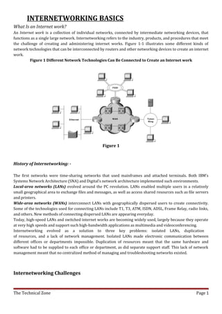
  • 1. INTERNETWORKING BASICS What Is an Internet work? An Internet work is a collection of individual networks, connected by intermediate networking devices, that functions as a single large network. Internetworking refers to the industry, products, and procedures that meet the challenge of creating and administering internet works. Figure 1-1 illustrates some different kinds of network technologies that can be interconnected by routers and other networking devices to create an internet work. Figure 1 Different Network Technologies Can Be Connected to Create an Internet work Figure 1 History of Internetworking: - The first networks were time-sharing networks that used mainframes and attached terminals. Both IBM’s Systems Network Architecture (SNA) and Digital’s network architecture implemented such environments. Local-area networks (LANs) evolved around the PC revolution. LANs enabled multiple users in a relatively small geographical area to exchange files and messages, as well as access shared resources such as file servers and printers. Wide-area networks (WANs) interconnect LANs with geographically dispersed users to create connectivity. Some of the technologies used for connecting LANs include T1, T3, ATM, ISDN, ADSL, Frame Relay, radio links, and others. New methods of connecting dispersed LANs are appearing everyday. Today, high-speed LANs and switched internet works are becoming widely used, largely because they operate at very high speeds and support such high-bandwidth applications as multimedia and videoconferencing. Internetworking evolved as a solution to three key problems: isolated LANs, duplication of resources, and a lack of network management. Isolated LANs made electronic communication between different offices or departments impossible. Duplication of resources meant that the same hardware and software had to be supplied to each office or department, as did separate support staff. This lack of network management meant that no centralized method of managing and troubleshooting networks existed. Internetworking Challenges The Technical Zone Page 1
  • 2. Implementing a functional internetwork is no simple task. Many challenges must be faced, especially in the areas of connectivity, reliability, network management, and flexibility. Each area is key in establishing an efficient and effective internetwork. The challenge when connecting various systems is to support communication among disparate technologies. Different sites, for example, may use different types of media operating at varying speeds, or may even include different types of systems that need to communicate. Because companies rely heavily on data communication, internetworks must provide a certain level of reliability. This is an unpredictable world; so many large internetworks include redundancy to allow for communication even when problems occur. Furthermore, network management must provide centralized support and troubleshooting capabilities in an internetwork. Configuration, security, performance, and other issues must be adequately addressed for the internetwork to function smoothly. Security within an internetwork is essential. Many people think of network security from the perspective of protecting the private network from outside attacks. However, it is just as important to protect the network from internal attacks, especially because most security breaches come from inside. Networks must also be secured so that the internal network cannot be used as a tool to attack other external sites. Early in the year 2000, many major web sites were the victims of distributed denial of service (DDOS) attacks. These attacks were possible because a great number of private networks currently connected with the Internet were not properly secured. These private networks were used as tools for the attackers. Because nothing in this world is stagnant, internetworks must be flexible enough to change with new demands. Internetworking Models When networks first came into being, computers could typically communicate only with computers from the same manufacturer. For example, companies ran either a complete DECnet solution or an IBM solution—not both together. In the late 1970s, the OSI (Open Systems Interconnection) model was created by the International Organization for Standardization (ISO) to break this barrier. The OSI model was meant to help vendors create interoperable network devices. Like world peace, it’ll probably never happen completely, but it’s still a great goal. The OSI model is the primary architectural model for networks. It describes how data and network information are communicated from applications on one computer, through the network media, to an application on another computer. The OSI reference model breaks this approach into layers. The Layered Approach A reference model is a conceptual blueprint of how communications should take place. It addresses all the processes required for effective communication and divides these processes into logical groupings called layers. When a communication system is designed in this manner, it’s known as layered architecture. Think of it like this: You and some friends want to start a company. One of the first things you’d do is sit down and think through what must be done, who will do them, what order they will be done in, and how they relate to each other. Ultimately, you might group these tasks into departments. Let’s say you decide to have an order- taking department, an inventory department, and a shipping department. Each of your departments has its own unique tasks, keeping its staff members busy and requiring them to focus on only their own duties. Similarly, software developers can use a reference model to understand computer communication processes and to see what types of functions need to be accomplished on any one layer. If they are developing a protocol for a certain layer, all they need to concern themselves with is the specific layer’s functions, not those of any other layer. Another layer and protocol will handle the other functions. The technical term for this idea is binding. The communication processes that are related to each other are bound, or grouped together, at a particular layer. The Technical Zone Page 2
  • 3. Advantages of Reference Models The OSI model is hierarchical, and the same benefits and advantages can apply to any layered model. The primary purpose of all models, and especially the OSI model, is to allow different vendors to interoperate. The benefits of the OSI model include, but are not limited to, the following: • Dividing the complex network operation into more manageable layers • Changing one layer without having to change all layers. This allows application developers to specialize in design and development. • Defining the standard interface for the “plug-and-play” multi-vendor integration Open System Interconnection Reference Model The Open System Interconnection (OSI) reference model describes how information from a software application in one computer moves through a network medium to a software application in another computer. The OSI reference model is a conceptual model composed of seven layers, each specifying particular network functions. The model was developed by the International Organization for Standardization (ISO) in 1984, and it is now considered the primary architectural model for interceptor communications. The OSI model divides the tasks involved with moving information between networked computers into seven smaller, more manageable task groups. A task or group of tasks is then assigned to each of the seven OSI layers. Each layer is reasonably self- contained so that the tasks assigned to each layer can be implemented independently. This enables the solutions offered by one layer to be updated without adversely affecting the other layers. The following list details the seven layers of the Open System Interconnection (OSI) reference model: • Layer 7—Application • Layer 6—Presentation • Layer 5—Session • Layer 4—Transport • Layer 3—Network • Layer 2—Data link • Layer 1—Physical The OSI Reference Model Contains Seven Independent Layers Application Presentation Sessions Transport Network Data-Link Physical Characteristics of the OSI Layers The seven layers of the OSI reference model can be divided into two categories: upper layers and lower layers. The upper layers of the OSI model deal with application issues and generally are implemented only in software. The highest layer, the application layer, is closest to the end user. Both users and application layer processes interact with software applications that contain a communications component. The term upper layer is sometimes used to refer to any layer above another layer in the OSI model. The Technical Zone Page 3
  • 4. The lower layers of the OSI model handle data transport issues. The physical layer and the data link layer are implemented in hardware and software. The lowest layer, the physical layer, is closest to the physical network medium (the network cabling, for example) and is responsible for actually placing information on the medium. Figure 2 illustrates the division between the upper and lower OSI layers. Figure 2: Two Sets of Layers Make Up the OSI Layers Protocols Application Application Presentation Session Transport Network Data Transport Data-Link Physical The OSI model provides a conceptual framework for communication between computers, but the model itself is not a method of communication. Actual communication is made possible by using communication protocols. In the context of data networking, a protocol is a formal set of rules and conventions that governs how computers exchange information over a network medium. A protocol implements the functions of one or more of the OSI layers. A wide variety of communication protocols exist. Some of these protocols include LAN protocols, WAN protocols, network protocols, and routing protocols. LAN protocols operate at the physical and data link layers of the OSI model and define communication over the various LAN media. WAN protocols operate at the lowest three layers of the OSI model and define communication over the various wide-area media. Routing protocols are network layer protocols that are responsible for exchanging information between routers so that the routers can select the proper path for network traffic. Finally, network protocols are the various upper-layer The Technical Zone Page 4
  • 5. protocols that exist in a given protocol suite. Many protocols rely on others for operation. For example, many routing protocols use network protocols to exchange information between routers. This concept of building upon the layers already in existence is the foundation of the OSI model. OSI Model and Communication between Systems Information being transferred from a software application in one computer system to a software application in another must pass through the OSI layers. For example, if a software application in System A has information to transmit to a software application in System B, the application program in System A will pass its information to the application layer (Layer 7) of System A. The application layer then passes the information to the presentation layer (Layer 6), which relays the data to the session layer (Layer 5), and so on down to the physical layer (Layer 1). At the physical layer, the information is placed on the physical network medium and is sent across the medium to System B. The physical layer of System B removes the information from the physical medium, and then its physical layer passes the information up to the data link layer (Layer 2), which passes it to the network layer (Layer 3), and so on, until it reaches the application layer (Layer 7) of System B. Finally, the application layer of System B passes the information to the recipient application program to complete the communication process. Interaction between OSI Model Layers A given layer in the OSI model generally communicates with three other OSI layers: the layer directly above it, the layer directly below it, and its peer layer in other networked computer systems. The data link layer in System A, for example, communicates with the network layer of System A, the physical layer of System A, and the data link layer in System B. Figure 1-4 illustrates this example. Figure 2 OSI Model Layers Communicate with Other Layers Figure 3 The Technical Zone Page 5
  • 6. Figure 3 OSI Model Layers and Information Exchange The seven OSI layers use various forms of control information to communicate with their peer layers in other computer systems. This control information consists of specific requests and instructions that are exchanged between peer OSI layers. Control information typically takes one of two forms: headers and trailers. Headers are prepended to data that has been passed down from upper layers. Trailers are appended to data that has been passed down from upper layers. An OSI layer is not required to attach a header or a trailer to data from upper layers. Headers, trailers, and data are relative concepts, depending on the layer that analyzes the information unit. At the network layer, for example, an information unit consists of a Layer 3 header and data. At the data link layer, however, all the information passed down by the network layer (the Layer 3 header and the data) is treated as data. In other words, the data portion of an information unit at a given OSI layer potentially can contain headers, trailers, and data from all the higher layers. This is known as encapsulation. Figure 1-6 shows how the header and data from one layer are encapsulated into the header of the next lowest layer. Figure 4: Headers and Data Can Be Encapsulated During Information Exchange Figure 4 The Technical Zone Page 6
  • 7. Information Exchange Process The information exchange process occurs between peer OSI layers. Each layer in the source system adds control information to data, and each layer in the destination system analyzes and removes the control information from that data. If System A has data from a software application to send to System B, the data is passed to the application layer. The application layer in System A then communicates any control information required by the application layer in System B by prepending a header to the data. The resulting information unit (a header and the data) is passed to the presentation layer, which prepends its own header containing control information intended for the presentation layer in System B. The information unit grows in size as each layer prepends its own header (and, in some cases, a trailer) that contains control information to be used by its peer layer in System B. At the physical layer, the entire information unit is placed onto the network medium. The physical layer in System B receives the information unit and passes it to the data link layer. The data link layer in System B then reads the control information contained in the header prepended by the data link layer in System A. The header is then removed, and the remainder of the information unit is passed to the network layer. Each layer performs the same actions: The layer reads the header from its peer layer, strips it off, and passes the remaining information unit to the next highest layer. After the application layer performs these actions, the data is passed to the recipient software application in System B, in exactly the form in which it was transmitted by the application in System A. OSI Model Physical Layer The physical layer defines the electrical, mechanical, procedural, and functional specifications for activating, maintaining, and deactivating the physical link between communicating network systems. Physical layer specifications define characteristics such as voltage levels, timing of voltage changes, physical data rates, maximum transmission distances, and physical connectors. Physical layer implementations can be categorized as either LAN or WAN specifications. Figure 1-7 illustrates some common LAN and WAN physical layer implementations. Figure 5: Physical Layer Implementations Can Be LAN or WAN Specifications Figure 5 • OSI Model Data Link Layer The data link layer provides reliable transit of data across a physical network link. Different data link layer specifications define different network and protocol characteristics, including physical addressing, network topology, error notification, sequencing of frames, and flow control. Physical addressing (as opposed to network addressing) defines how devices are addressed at the data link layer. Network topology consists of the The Technical Zone Page 7
  • 8. data link layer specifications that often define how devices are to be physically connected, such as in a bus or a ring topology. Error notification alerts upper-layer protocols that a transmission error has occurred, and the sequencing of data frames reorders frames that are transmitted out of sequence. Finally, flow control moderates the transmission of data so that the receiving device is not overwhelmed with more traffic than it can handle at one time. The Institute of Electrical and Electronics Engineers (IEEE) has subdivided the data link layer into two sub layers: Logical Link Control (LLC) and Media Access Control (MAC). Figure 1-8 illustrates the IEEE sub layers of the data link layer. Figure 6: The Data Link Layer Contains Two Sub layers Figure 6 The Logical Link Control (LLC) sub layer of the data link layer manages communications between devices over a single link of a network. LLC is defined in the IEEE 802.2 specification and supports both connectionless and connection-oriented services used by higher-layer protocols. IEEE 802.2 defines a number of fields in data link layer frames that enable multiple higher-layer protocols to share a single physical data link. The Media Access Control (MAC) sub layer of the data link layer manages protocol access to the physical network medium. The IEEE MAC specification defines MAC addresses, which enable multiple devices to uniquely identify one another at the data link layer. • OSI Model Network Layer The network layer defines the network address, which differs from the MAC address. Some network layer implementations, such as the Internet Protocol (IP), define network addresses in a way that route selection can be determined systematically by comparing the source network address with the destination network address and applying the subnet mask. Because this layer defines the logical network layout, routers can use this layer to determine how to forward packets. Because of this, much of the design and configuration work for internet works happens at Layer 3, the network layer. • OSI Model Transport Layer The transport layer accepts data from the session layer and segments the data for transport across the network. Generally, the transport layer is responsible for making sure that the data is delivered error-free and in the proper sequence. Flow control generally occurs at the transport layer. Flow control manages data transmission between devices so that the transmitting device does not send more data than the receiving device can process. Multiplexing enables data from several applications to be transmitted onto a single physical link. Virtual circuits are established, maintained, and terminated by the transport layer. Error checking involves creating various mechanisms for detecting transmission errors, while error recovery involves acting, such as requesting that data be retransmitted, to resolve any errors that occur. The transport protocols used on the Internet are TCP and UDP. Flow Control Basics Flow control is a function that prevents network congestion by ensuring that transmitting devices do not overwhelm receiving devices with data. A high-speed computer, for example, may generate traffic faster than the network can transfer it, or faster than the destination device can receive and process it. The three The Technical Zone Page 8
  • 9. commonly used methods for handling network congestion are buffering, transmitting source-quench messages, and windowing. Buffering is used by network devices to temporarily store bursts of excess data in memory until they can be processed. Occasional data bursts are easily handled by buffering. Excess data bursts can exhaust memory, however, forcing the device to discard any additional datagrams that arrive. Source-quench messages are used by receiving devices to help prevent their buffers from overflowing. The receiving device sends source-quench messages to request that the source reduce its current rate of data transmission. First, the receiving device begins discarding received data due to overflowing buffers. Second, the receiving device begins sending source-quench messages to the transmitting device at the rate of one message for each packet dropped. The source device receives the source-quench messages and lowers the data rate until it stops receiving the messages. Finally, the source device then gradually increases the data rate as long as no further source-quench requests are received. Windowing is a flow-control scheme in which the source device requires an acknowledgment from the destination after a certain number of packets have been transmitted. With a window size of 3, the source requires an acknowledgment after sending three packets, as follows. First, the source device sends three packets to the destination device. Then, after receiving the three packets, the destination device sends an acknowledgment to the source. The source receives the acknowledgment and sends three more packets. If the destination does not receive one or more of the packets for some reason, such as overflowing buffers, it does not receive enough packets to send an acknowledgment. The source then retransmits the packets at a reduced transmission rate. Error-Checking Basics Error-checking schemes determine whether transmitted data has become corrupt or otherwise damaged while traveling from the source to the destination. Error checking is implemented at several of the OSI layers. One common error-checking scheme is the cyclic redundancy check (CRC), which detects and discards corrupted data. Error-correction functions (such as data retransmission) are left to higher-layer protocols. A CRC value is generated by a calculation that is performed at the source device. The destination device compares this value to its own calculation to determine whether errors occurred during transmission. First, the source device performs a predetermined set of calculations over the contents of the packet to be sent. Then, the source places the calculated value in the packet and sends the packet to the destination. The destination performs the same predetermined set of calculations over the contents of the packet and then compares its computed value with that contained in the packet. If the values are equal, the packet is considered valid. If the values are unequal, the packet contains errors and is discarded. • OSI Model Session Layer The Session layer is responsible for setting up, managing, and then tearing down sessions between Presentation layer entities. The Session layer also provides dialog control between devices, or nodes. It coordinates communication between systems and serves to organize their communication by offering three different modes: • Simplex • half-duplex • full-duplex The Session layer basically keeps different applications’ data separate from other applications data. • OSI Model Presentation Layer The Presentation layer gets its name from its purpose: It presents data to the Application layer. It’s essentially a translator and provides coding and conversion functions. A successful data transfer technique is to adapt the data into a standard format before transmission. Computers are configured to receive this generically formatted data and then convert the data back into its native format for actual reading (for example, EBCDIC to ASCII). By providing translation services, the Presentation layer ensures that data transferred from the Application layer of one system can be read by the Application layer of another host. The OSI has protocol The Technical Zone Page 9
  • 10. standards that define how standard data should be formatted. Tasks like data compression, decompression, encryption, and decryption are associated with this layer. Some Presentation layer standards are involved in multimedia operations. The following serve to direct graphic and visual image presentation: PICT: This is picture format used by Macintosh or PowerPC programs for transferring Quick Draw graphics. TIFF: The Tagged Image File Format is a standard graphics format for high-resolution, bitmapped images. JPEG: The Joint Photographic Experts Group brings these photo standards to us. Other standards guide movies and sound. MIDI: The Musical Instrument Digital Interface is used for digitized music. MPEG: The Moving Picture Experts Group’s standard for the compression and coding of motion video for CDs is increasingly popular. It provides digital storage and bit rates up to 1.5Mbps . • OSI Model Application Layer The application layer is the OSI layer closest to the end user, which means that both the OSI application layer and the user interact directly with the software application. This layer interacts with software applications that implement a communicating component. Such application programs fall outside the scope of the OSI model. Application layer functions typically include identifying communication partners, determining resource availability, and synchronizing communication. When identifying communication partners, the application layer determines the identity and availability of communication partners for an application with data to transmit. When determining resource availability, the application layer must decide whether sufficient network resources for the requested communication exist. In synchronizing communication, all communication between applications requires cooperation that is managed by the application layer. Some examples of application layer implementations include Telnet, File Transfer Protocol (FTP), and Simple Mail Transfer Protocol (SMTP). Information Formats The data and control information that is transmitted through internetworks takes a variety of forms. The terms used to refer to these information formats are not used consistently in the internetworking industry but sometimes are used interchangeably. Common information formats include frames, packets, datagrams, segments, messages, cells, and data units. A frame is an information unit whose source and destination are data link layer entities. A frame is composed of the data link layer header (and possibly a trailer) and upper-layer data. The header and trailer contain control information intended for the data link layer entity in the destination system. Data from upper-layer entities is encapsulated in the data link layer header and trailer. Figure 1-9 illustrates the basic components of a data link layer frame. Figure 7: Data from Upper-Layer Entities Makes Up the Data Link Layer Frame Figure 7 A packet is an information unit whose source and destination are network layer entities. A packet is composed of the network layer header (and possibly a trailer) and upper-layer data. The header and trailer contain control information intended for the network layer entity in the destination system. Data from upper-layer entities is encapsulated in the network layer header and trailer. Figure 1-10 illustrates the basic components of a network layer packet. The Technical Zone Page 10
  • 11. Figure 8: Three Basic Components Make Up a Network Layer Packet Figure 8 The term datagram usually refers to an information unit whose source and destination are network layer entities that use connectionless network service. The term segment usually refers to an information unit whose source and destination are transport layer entities. A message is an information unit whose source and destination entities exist above the network layer (often at the application layer). A cell is an information unit of a fixed size whose source and destination are data link layer entities. Cells are used in switched environments, such as Asynchronous Transfer Mode (ATM) and Switched Multimegabit Data Service (SMDS) networks. A cell is composed of the header and payload. The header contains control information intended for the destination data link layer entity and is typically 5 bytes long. The payload contains upper-layer data that is encapsulated in the cell header and is typically 48 bytes long. The length of the header and the payload fields always are the same for each cell. Figure 1picts the components of a typical cell. Figure below Two Components Make Up a Typical Cell Figure 9 Data unit is a generic term that refers to a variety of information units. Some common data units are service data units (SDUs), protocol data units, and bridge protocol data units (BPDUs). SDUs are information units from upper-layer protocols that define a service request to a lower-layer protocol. PDU is OSI terminology for a packet. BPDUs are used by the spanning-tree algorithm as hello messages . Connection-Oriented and Connectionless Network Services In general, transport protocols can be characterized as being either connection-oriented or connectionless. Connection-oriented services must first establish a connection with the desired service before passing any data. A connectionless service can send the data without any need to establish a connection first. In general, connection-oriented services provide some level of delivery guarantee, whereas connectionless services do not. Connection-oriented service involves three phases: connection establishment, data transfer, and connection termination. During connection establishment, the end nodes may reserve resources for the connection. The end nodes also may negotiate and establish certain criteria for the transfer, such as a window size used in TCP connections. This resource reservation is one of the things exploited in some denial of service (DOS) attacks. An attacking system will send many requests for establishing a connection but then will never complete the connection. The The Technical Zone Page 11
  • 12. attacked computer is then left with resources allocated for many never-completed connections. Then, when an end node tries to complete an actual connection, there are not enough resources for the valid connection. The data transfer phase occurs when the actual data is transmitted over the connection. During data transfer, most connection-oriented services will monitor for lost packets and handle resending them. The protocol is generally also responsible for putting the packets in the right sequence before passing the data up the protocol stack. When the transfer of data is complete, the end nodes terminate the connection and release resources reserved for the connection. Connection-oriented network services have more overhead than connectionless ones. Connection-oriented services must negotiate a connection, transfer data, and tear down the connection, whereas a connectionless transfer can simply send the data without the added overhead of creating and tearing down a connection. Each has its place in internetworks. MAC Addresses Media Access Control (MAC) addresses consist of a subset of data link layer addresses. MAC addresses identify network entities in LANs that implement the IEEE MAC addresses of the data link layer. As with most data-link addresses, MAC addresses are unique for each LAN interface. Figure 1-14 illustrates the relationship between MAC addresses, data-link addresses, and the IEEE sub layers of the data link layer. Figure 10: MAC Addresses, Data-Link Addresses, and the IEEE Sub layers of the Data Link Layer Are All Related Figure 10 MAC addresses are 48 bits in length and are expressed as 12 hexadecimal digits. The first 6 hexadecimal digits, which are administered by the IEEE, identify the manufacturer or vendor and thus comprise the Organizationally Unique Identifier (OUI). The last 6 hexadecimal digits comprise the interface serial number, or another value administered by the specific vendor. MAC addresses sometimes are called burned-in addresses (BIAs) because they are burned into read-only memory (ROM) and are copied into random-access memory (RAM) when the interface card initializes. Figure 1-15 illustrates the MAC address format. The Technical Zone Page 12
  • 13. Figure 11: The MAC Address Contains a Unique Format of Hexadecimal Digits Figure 11 Mapping Addresses Because internetworks generally use network addresses to route traffic around the network, there is a need to map network addresses to MAC addresses. When the network layer has determined the destination station's network address, it must forward the information over a physical network using a MAC address. Different protocol suites use different methods to perform this mapping, but the most popular is Address Resolution Protocol (ARP). Different protocol suites use different methods for determining the MAC address of a device. The following three methods are used most often. Address Resolution Protocol (ARP) maps network addresses to MAC addresses. The Hello protocol enables network devices to learn the MAC addresses of other network devices. MAC addresses either are embedded in the network layer address or are generated by an algorithm. Address Resolution Protocol (ARP) is the method used in the TCP/IP suite. When a network device needs to send data to another device on the same network, it knows the source and destination network addresses for the data transfer. It must somehow map the destination address to a MAC address before forwarding the data. First, the sending station will check its ARP table to see if it has already discovered this destination station's MAC address. If it has not, it will send a broadcast on the network with the destination station's IP address contained in the broadcast. Every station on the network receives the broadcast and compares the embedded IP address to its own. Only the station with the matching IP address replies to the sending station with a packet containing the MAC address for the station. The first station then adds this information to its ARP table for future reference and proceeds to transfer the data. When the destination device lies on a remote network, one beyond a router, the process is the same except that the sending station sends the ARP request for the MAC address of its default gateway. It then forwards the information to that device. The default gateway will then forward the information over whatever networks necessary to deliver the packet to the network on which the destination device resides. The router on the destination device's network then uses ARP to obtain the MAC of the actual destination device and delivers the packet. The Hello protocol is a network layer protocol that enables network devices to identify one another and indicate that they are still functional. When a new end system powers up, for example, it broadcasts hello messages onto the network. Devices on the network then return hello replies, and hello messages are also sent at specific intervals to indicate that they are still functional. Network devices can learn the MAC addresses of other devices by examining Hello protocol packets. . The Technical Zone Page 13
  • 14. Network Layer Addresses A network layer address identifies an entity at the network layer of the OSI layers. Network addresses usually exist within a hierarchical address space and sometimes are called virtual or logical addresses. The relationship between a network address and a device is logical and unfixed; it typically is based either on physical network characteristics (the device is on a particular network segment) or on groupings that have no physical basis (the device is part of an AppleTalk zone). End systems require one network layer address for each network layer protocol that they support. (This assumes that the device has only one physical network connection.) Routers and other internetworking devices require one network layer address per physical network connection for each network layer protocol supported. For example, a router with three interfaces each running AppleTalk, TCP/IP, and OSI must have three network layer addresses for each interface. The router therefore has nine network layer addresses. Figure 1-16 illustrates how each network interface must be assigned a network address for each protocol supported. Figure 12: Each Network Interface Must Be Assigned a Network Address for Each Protocol supported Figure 12 The Technical Zone Page 14
  • 15. Address Assignments Addresses are assigned to devices as one of two types: static and dynamic. Static addresses are assigned by a network administrator according to a preconceived internetwork addressing plan. A static address does not change until the network administrator manually changes it. Dynamic addresses are obtained by devices when they attach to a network, by means of some protocol-specific process. A device using a dynamic address often has a different address each time that it connects to the network. Some networks use a server to assign addresses. Server-assigned addresses are recycled for reuse as devices disconnect. A device is therefore likely to have a different address each time that it connects to the network. Addresses versus Names Internet work devices usually have both a name and an address associated with them. Internet work names typically are location-independent and remain associated with a device wherever that device moves (for example, from one building to another). Internetwork addresses usually are location-dependent and change when a device is moved (although MAC addresses are an exception to this rule). As with network addresses being mapped to MAC addresses, names are usually mapped to network addresses through some protocol. The Internet uses Domain Name System (DNS) to map the name of a device to its IP address. For example, it's easier for you to remember www.cisco.com instead of some IP address. Therefore, you type www.cisco.com into your browser when you want to access Cisco's web site. Your computer performs a DNS lookup of the IP address for Cisco's web server and then communicates with it using the network address. TCP/IP Model The TCP/IP model is a condensed version of the OSI model. It is comprised of four, instead of seven, layers: • The Process/Application layer • The Host-to-Host layer • The Internet layer • The Network Access layer Figure given bellow shows a comparison of the TCP/IP or DoD model and the OSI reference model. As you can see, the two are similar in concept, but each has a different number of layers with different names. A vast array of protocols combines at the DoD model’s Process/Application layer to integrate the various activities and duties spanning the focus of the OSI’s corresponding top three layers (Application, Presentation, and Session). The Process/Application layer defines protocols for node-to-node application communication and also controls user-interface specifications. The Host-to-Host layer parallels the functions of the OSI’s Transport The Technical Zone Page 15
  • 16. layer, defining protocols for setting up the level of transmission service for applications. It tackles issues like creating reliable end-to-end communication and ensuring the error-free delivery of data. It handles packet sequencing and maintains data integrity. The Internet layer corresponds to the OSI’s Network layer, designating the protocols relating to the logical transmission of packets over the entire network. It takes care of the addressing of hosts by giving them an IP (Internet Protocol) address, and it handles the routing of packets among multiple networks. It also controls the communication flow between two hosts. At the bottom of the model, the Network Access layer monitors the data exchange between the host and the network. The equivalent of the Data Link and Physical layers of the OSI model, the Network Access layer oversees hardware addressing and defines protocols for the physical transmission of data. While the DoD and OSI models are alike in design and concept and have similar functions in similar places, how those functions occur is different. Figure given bellow shows the TCP/IP protocol suite and how its protocols relate to the DoD model layers. The Process/Application Layer Protocols In this section, we will describe the different applications and services typically used in IP networks. The different protocols and applications covered in this section include the following: • TELNET • FTP • TFTP • NFS • SMTP • LPD • X Window • SNMP • DNS • DHCP Telnet Telnet is the chameleon of protocols—its specialty is terminal emulation. It allows a user on a remote client machine, called the Telnet client, to access the resources of another machine, the Telnet server. Telnet achieves this by pulling a fast one on the Telnet server and making the client machine appear as though it were a terminal directly attached to the local network. This projection is actually a software image, a virtual terminal The Technical Zone Page 16
  • 17. that can interact with the chosen remote host. These emulated terminals are of the text-mode type and can execute refined procedures like displaying menus that give users the opportunity to choose options from them and access the applications on the duped server. Users begin a Telnet session by running the Telnet client software and then logging on to the Telnet server. File Transfer Protocol (FTP) The File Transfer Protocol (FTP) is the protocol that actually lets us transfer files; it can facilitate this between any two machines using it. But FTP isn’t just a protocol; it’s also a program. Operating as a protocol, FTP is used by applications. As a program, it’s employed by users to perform file tasks by hand. FTP also allows for access to both directories and files and can accomplish certain types of directory operations, like relocating into different ones. FTP teams up with Telnet to transparently log you in to the FTP server and then provides for the transfer of files. Accessing a host through FTP is only the first step, though. Users must then be subjected to an authentication login that’s probably secured with passwords and usernames implemented by system administrators to restrict access. But you can get around this somewhat by adopting the username “anonymous”—though what you’ll gain access to will be limited. Even when employed by users manually as a program, FTP’s functions are limited to listing and manipulating directories, typing file contents, and copying files between hosts. It can’t execute remote files as programs. Trivial File Transfer Protocol (TFTP) The Trivial File Transfer Protocol (TFTP) is the stripped-down, stock version of FTP, but it’s the protocol of choice if you know exactly what you want and where to find it. It doesn’t give you the abundance of functions that FTP does, though. TFTP has no directory-browsing abilities; it can do nothing but send and receive files. This compact little protocol also skimps in the data department, sending much smaller blocks of data than FTP, and there’s no authentication as with FTP, so it’s insecure. Few sites support it because of the inherent security risks. Network File System (NFS) Network File System (NFS) is a jewel of a protocol specializing in file sharing. It allows two different types of file systems to interoperate. It works like this: Suppose the NFS server software is running on an NT server, and the NFS client software is running on a Unix host. NFS allows for a portion of the RAM on the NT server to transparently store Unix files, which can, in turn, be used by Unix users. Even though the NT file system and Unix file system are unlike—they have different case sensitivity, filename lengths, security, and so on—both Unix users and NT users can access that same file with their normal file systems, in their normal way. Simple Mail Transfer Protocol (SMTP) Simple Mail Transfer Protocol (SMTP), answering our ubiquitous call to e-mail, uses a spooled, or queued, method of mail delivery. Once a message has been sent to a destination, the message is spooled to a device— usually a disk. The server software at the destination posts a vigil, regularly checking this queue for messages. When it detects them, it proceeds to deliver them to their destination. SMTP is used to send mail; POP3 is used to receive mail. Line Printer Daemon (LPD) The Line Printer Daemon (LPD) protocol is designed for printer sharing. The LPD, along with the LPR (Line Printer) program, allows print jobs to be spooled and sent to the network’s printers using TCP/IP. X Window Designed for client-server operations, X Window defines a protocol for the writing of graphical user interface– based client/server applications. The idea is to allow a program, called a client, to run on one computer and have it display a program called a window server on another computer. Simple Network Management Protocol (SNMP) The Technical Zone Page 17
  • 18. Simple Network Management Protocol (SNMP) collects and manipulates this valuable network information. It gathers data by polling the devices on the network from a management station at fixed or random intervals, requiring them to disclose certain information. When all is well, SNMP receives something called a baseline— a report delimiting the operational traits of a healthy network. This protocol can also stand as a watchdog over the network, quickly notifying managers of any sudden turn of events. These network watchdogs are called agents, and when aberrations occur, agents send an alert called a trap to the management station. Domain Name Service (DNS) Domain Name Service (DNS) resolves host names, specifically Internet names, like www.routersim.com. You don’t have to use DNS; you can just type in the IP address of any device you want to communicate with. An IP address identifies hosts on a network and the Internet as well. However, DNS was designed to make our lives easier. Also, what would happen if you wanted to move your Web page to a different service provider? The IP address would change and no one would know what the new one was. DNS allows you to use a domain name to specify an IP address. You can change the IP address as often as you want and no one will know the difference. The Host-to-Host Layer Protocols The Host-to-Host layer’s main purpose is to shield the upper-layer applications from the complexities of the network. This layer says to the upper layer, “Just give me your data stream, with any instructions, and I’ll begin the process of getting your information ready to send.” The following sections describe the two protocols at this layer: • Transmission Control Protocol (TCP) • User Datagram Protocol (UDP) Transmission Control Protocol (TCP) The Transmission Control Protocol (TCP) takes large blocks of information from an application and breaks them into segments. It numbers and sequences each segment so that the destination’s TCP protocol can put the segments back into the order the application intended. After these segments are sent, TCP (on the transmitting host) waits for an acknowledgment of the receiving end’s TCP virtual circuit session, retransmitting those that aren’t acknowledged. Before a transmitting host starts to send segments down the model, the sender’s TCP protocol contacts the destination’s TCP protocol to establish a connection. What is created is known as a virtual circuit. This type of communication is called connection-oriented. During this initial handshake, the two TCP layers also agree on the amount of information that’s going to be sent before the recipient’s TCP sends back an acknowledgment. With everything agreed upon in advance, the path is paved for reliable communication to take place. TCP is a full-duplex, connection-oriented, reliable, accurate protocol, and establishing all these terms and conditions, in addition to error checking, is no small task. TCP is very complicated and, not surprisingly, costly in terms of network overhead. Since today’s networks are much more reliable than those of yore, this added reliability is often unnecessary. User Datagram Protocol (UDP) Application developers can use the User Datagram Protocol (UDP) in place of TCP. UDP is the scaled-down economy model and is considered a thin protocol. Like a thin person on a park bench, a thin protocol doesn’t take up a lot of room—or in this case, much bandwidth on a network. UDP also doesn’t offer all the bells and whistles of TCP, but it does do a fabulous job of transporting information that doesn’t require reliable delivery — and it does so using far fewer network resources. There are some situations where it would definitely be wise for application developers to opt for UDP rather than TCP. Remember the watchdog SNMP up there at the Process/Application layer? SNMP monitors the network, sending intermittent messages and a fairly steady flow of status updates and alerts, especially when running on a large network. The cost in overhead to establish, maintain, and close a TCP connection for each one of those little messages would reduce what would be an otherwise healthy, efficient network to a dammed-up bog in no time. Another circumstance calling for UDP over TCP is when the matter of reliability is already accomplished at the Process/Application layer. Network File System (NFS) handles its own reliability issues, making the use of TCP both impractical and redundant. However, the application developer decides whether to use UDP or TCP, not the user who wants to transfer The Technical Zone Page 18
  • 19. data faster. UDP receives upper-layer blocks of information, instead of data streams as TCP does, and breaks them into segments. Like TCP, each UDP segment is given a number for reassembly into the intended block at the destination. However, UDP does not sequence the segments and does not care in which order the segments arrive at the destination. At least it numbers them, though. But after that, UDP sends the segments off and forgets about them. It doesn’t follow through, check up on them, or even allow for an acknowledgment of safe arrival—complete abandonment. Because of this, it’s referred to as an unreliable protocol. This does not mean that UDP is ineffective, only that it doesn’t handle issues of reliability. Further, UDP doesn’t create a virtual circuit, nor does it contact the destination before delivering information to it. It is, therefore, also considered a connectionless protocol. Since UDP assumes that the application will use its own reliability method, it doesn’t use any. This gives an application developer a choice when running the Internet Protocol stack: TCP for reliability or UDP for faster transfers. The Internet Layer Protocols There are two main reasons for the Internet layer’s existence: routing, and providing a single network interface to the upper layers. None of the upper- or lower-layer protocols have any functions relating to routing. The complex and important task of routing is the job of the Internet layer. The Internet layer’s second job is to provide a single network interface to the upper-layer protocols. Without this layer, application programmers would need to write “hooks” into every one of their applications for each different Network Access protocol. This would not only be a pain in the neck, but it would lead to different versions of each application—one for Ethernet, another one for Token Ring, and so on. To prevent this, IP provides one single network interface for the upper-layer protocols. That accomplished, it’s then the job of IP and the various Network Access protocols to get along and work together. All network roads don’t lead to Rome—they lead to IP. And all the other protocols at this layer, as well as all those at the upper layers, use it. Never forget that. All paths through the model go through IP. The following sections describe the protocols at the Internet layer. These are the protocols that work at the Internet layer: • Internet Protocol (IP) • Internet Control Message Protocol (ICMP) • Address Resolution Protocol (ARP) • Reverse Address Resolution Protocol (RARP) Internet Protocol (IP) The Internet Protocol (IP) essentially is the Internet layer. The other protocols found here merely exist to support it. IP contains the big picture and could be said to “see all,” in that it is aware of all the interconnected networks. It can do this because all the machines on the network have software, or logical, address called an IP address. IP looks at each packet’s address. Then, using a routing table, it decides where a packet is to be sent next, choosing the best path. The Network Access–layer protocols at the bottom of the model don’t possess IP’s enlightened scope of the entire network; they deal only with physical links (local networks). Identifying devices on networks requires answering these two questions: Which network is it on? And what is its ID on that network? The first answer is the software, or logical, address (the correct street). The second answer is the hardware address (the correct mailbox). All hosts on a network have a logical ID called an IP address. This is the software, or logical, address and contains valuable encoded information greatly simplifying the complex task of routing. IP receives segments from the Host-to-Host layer and fragments them into datagrams (packets). IP then reassembles datagrams back into segments on the receiving side. Each datagram is assigned the IP address of the sender and of the recipient. Each router (layer-3 device) that receives a datagram makes routing decisions based upon the packet’s destination IP address. IP protocol has to go through every time user data is sent from the upper layers and wants to be sent to a remote network. Internet Control Message Protocol (ICMP) The Internet Control Message Protocol (ICMP) works at the Network layer and is used by IP for many different services. ICMP is a management protocol and messaging service provider for IP. Its messages are carried as IP datagrams. RFC 1256, ICMP Router Discovery Messages, is an annex to ICMP, which affords hosts’ extended The Technical Zone Page 19
  • 20. capability in discovering routes to gateways. Periodically, router advertisements are announced over the network, reporting IP addresses for the routers network interfaces. Hosts listen for these network infomercials to acquire route information. A router solicitation is a request for immediate advertisements and may be sent by a host when it starts up. If a router can’t send an IP datagram any further, it uses ICMP to send a message back to the sender, advising it of the situation. For example, if a router receives a packet destined for a network that the router doesn’t know about, it will send an ICMP Destination Unreachable message back to the sending station. Buffer Full: If a router’s memory buffer for receiving incoming datagrams is full, it will use ICMP to send out this message. Hops: Each IP datagram is allotted a certain number of routers, called hops, which it may go through. If it reaches its limit of hops before arriving at its destination, the last router to receive that datagram deletes it. The executioner router then uses ICMP to send an obituary message, informing the sending machine of the demise of its datagram. Ping: Packet Internet Groper uses ICMP echo messages to check the physical connectivity of machines on an internetwork. Trace route: Using ICMP timeouts, trace route is used to find a path a packet takes as it traverses an internetwork. The following data is from a network analyzer catching an ICMP echo request. Notice that even though ICMP works at the Network layer, it still uses IP to do the Ping request. Address Resolution Protocol (ARP) The Address Resolution Protocol (ARP) finds the hardware address of a host from a known IP address. Here’s how it works: When IP has a datagram to send, it must inform a Network Access protocol, such as Ethernet or Token Ring, of the destination’s hardware address on the local network. (It has already been informed by upper-layer protocols of the destination’s IP address.) If IP doesn’t find the destination host’s hardware address in the ARP cache, it uses ARP to find this information. As IP’s detective, ARP interrogates the local network by sending out a broadcast asking the machine with the specified IP address to reply with its hardware address. In other words, ARP translates the software (IP) address into a hardware address—for example, the destination machine’s Ethernet board address—and from it, deduces its whereabouts. This hardware address is technically referred to as the media access control (MAC) address or physical address. Figure given bellow shows how an ARP might look to a local network. Reverse Address Resolution Protocol (RARP) When an IP machine happens to be a diskless machine, it has no way of initially knowing its IP address, but it does know its MAC address. The Reverse Address Resolution Protocol (RARP) discovers the identity of the IP address for diskless machines by sending out a packet that includes its MAC address and a request for the IP The Technical Zone Page 20
  • 21. address assigned to that MAC address. A designated machine, called a RARP server, responds with the answer, and the identity crisis is over. RARP uses the information it does know about the machine’s MAC address to learn its IP address and complete the machine’s ID portrait. Ways of Communication Unicasting • Communication between two devices is one-on-one. Create least traffic while communicating. Best in when one device want to communicate with one device only as no extra bothering the other hosts on the segment. Cannot be use in one-on-many devices to communicate as one hub device need to send the many copies of the same packet to all the hosts and will get the Acks from them. Broadcasting • Communication between two devices is one-on-all. One-n-all means all the host in the network on the same switch. When host send the packet on broadcast address then the switch will duplicate the packet and will send it on all the host in the network. Multicasting • Communication with one-on-one and one-on-many has too many limitations like large traffic to handle and security breach. It is used when one-on-group one way communication is required. For example live telecasting of video stream on internet, in this case the users are group of people who may need the particular stream but not all the hosts. So the user will join the particular multicast group to get that particular stream. IP Addressing One of the most important topics in any discussion of TCP/IP is IP addressing. An IP address is a numeric identifier assigned to each machine on an IP network. It designates the location of a device on the network. An IP address is a software address, not a hardware address—the latter is hardcoded on a network interface card (NIC) and used for finding hosts on a local network. IP addressing was designed to allow a host on one network to communicate with a host on a different network, regardless of the type of LANs the hosts is participating in. IP stands for Internet Protocol, it's a communications protocol used from the smallest private network to the massive global Internet. An IP address is a unique identifier given to a single device on an IP network. The IP address consists of a 32-bit number that ranges from 0 to 4294967295. This means that theoretically, the Internet can contain approximately 4.3 billion unique objects. But to make such The Technical Zone Page 21
  • 22. a large address block easier to handle, it was chopped up into four 8-bit numbers, or "octets," separated by a period. Instead of 32 binary base-2 digits, which would be too long to read, it's converted to four base-256 digits. Octets are made up of numbers ranging from 0 to 255. The numbers below show how IP addresses increment. 0.0.0.0 0.0.0.1 ...increment 252 hosts... 0.0.0.254 0.0.0.255 0.0.1.0 0.0.1.1 ...increment 252 hosts.. 0.0.1.254 0.0.1.255 0.0.2.0 0.0.2.1 ...increment 4+ billion hosts... 255.255.255.255 IP Terminology Here are a few of the most important terms: - Bit One digit; either a 1 or a 0. Byte 8 bits. Octet Always 8 bits. Base-8 addressing scheme. Network address The designation used in routing to send packets to a remote network, for example, 10.0.0.0, 172.16.0.0, and 192.168.10.0. Broadcast address Used by applications and hosts to send information to all nodes on a network. Examples include 255.255.255.255, which is all networks, all nodes; 172.16.255.255, which is all subnets and hosts on network 17.16.0.0; and 10.255.255.255, which broadcasts to all subnets and hosts on network 10.0.0.0. The Technical Zone Page 22
  • 23. The Hierarchical IP Addressing Scheme An IP address consists of 32 bits of information. These bits are divided into four sections, referred to as octets or bytes, each containing 1 byte (8 bits). You can depict an IP address using one of three methods: • Dotted-decimal, as in 172.16.30.56 • Binary, as in 10101100.00010000.00011110.00111000 • Hexadecimal, as in 82 39 1E 38 Network Addressing The Technical Zone Page 23
  • 24. The network address uniquely identifies each network. Every machine on the same network shares that network address as part of its IP address. In the IP address 172.16.30.56, for example, 172.16 is the network address. The node address is assigned to, and uniquely identifies, each machine on a network. This part of the address must be unique because it identifies a particular machine—an individual—as opposed to a network, which is a group. This number can also be referred to as a host address. In the sample IP address 172.16.30.56, .30.56 is the node address. The designers of the Internet decided to create classes of networks based on network size. For the small number of networks possessing a very large number of nodes, they created the rank Class A network. At the other extreme is the Class C network, which is reserved for the numerous networks with a small number of nodes. The class distinction for networks between very large and very small is predictably called the Class B network. Subdividing an IP address into a network and node address is determined by the class designation of one’s network. Figure summarizes the three classes of networks: - Network Address Range: Class A The designers of the IP address scheme said that the first bit of the first byte in a Class A network address must always be off, or 0. This means a Class A address must be between 0 and 127. Here is how those numbers are defined: 0xxxxxxx: If we turn the other 7 bits all off and then turn them all on, we will find your Class A range of network addresses. 00000000=0 01111111=127 Network Address Range: Class B In a Class B network, the RFCs state that the first bit of the first byte must always be turned on, but the second bit must always be turned off. If you turn the other six bits all off and then all on, you will find the range for a Class B network: 10000000=128 10111111=191 As you can see, this means that a Class B network can be defined when the first byte is configured from 128 to 191. Network Address Range: Class C For Class C networks, the RFCs define the first two bits of the first octet always turned on, but the third bit can never be on. Following the same process as the previous classes, convert from binary to decimal to find the range. Here is the range for a Class C network: 11000000=192 11011111=223 The Technical Zone Page 24
  • 25. So, if you see an IP address that starts at 192 and goes to 223, you’ll know it is a Class C IP address. Network Address Ranges: Classes D and E The addresses between 224 and 255 are reserved for Class D and E networks. Class D is used for multicast addresses and Class E for scientific purposes. Network Addresses: Special Purpose Some IP addresses are reserved for special purposes, and network administrators shouldn’t assign these addresses to nodes. Table given bellow lists the members of this exclusive little club and why they’re included in it. Network –Id • Can be defined as the Id to represent the no. of host addresses in the same network in the topology. Cannot be assign to any host in the network. When all the host past is zero then it is called network-id. Or simply the first address of the network is always Network-Id Broadcast-Id • Address on which if packets are send these will be receive by all the hosts in the network. T his address is used when all the host in the network are suppose to get the same message. Cannot be assign to any host in the network. When all the host bits are one then it is called broadcast-id. Simply the last address of the network is called broadcast-id. Class A Addresses In a Class A network address, the first byte is assigned to the network address and the three remaining bytes are used for the node addresses. The Class A format is Network.Node.Node.Node For example, in the IP address 49.22.102.70, 49 is the network address, and 22.102.70 is the node address. Every machine on this particular network would have the distinctive network address of 49. Class A addresses are one byte long, with The Technical Zone Page 25
  • 26. the first bit of that byte reserved and the seven remaining bits available for manipulation. As a result, the maximum number of Class A networks that can be created is 128. Why? Because each of the seven bit positions can either be a 0 or a 1, thus 27 or 128. To complicate matters further, the network address of all 0s (0000 0000) is reserved to designate the default route. Additionally, the address 127, which is reserved for diagnostics, can’t be used either, which means that you can only use the numbers 1 to 126 to designate Class A network addresses. This means the actual number of usable Class A network addresses is 128 minus 2, or 126. Got it? Each Class A address has three bytes (24-bit positions) for the node address of a machine. Thus, there are 224—or 16,777,216—unique combinations and, therefore, precisely that many possible unique node addresses for each Class A network. Because addresses with the two patterns of all 0s and all 1s are reserved, the actual maximum usable number of nodes for a Class A network is 224 minus 2, which equals 16,777,214. Class A Valid Host IDs Here is an example of how to figure out the valid host IDs in a Class A network address: 10.0.0.0 All host bits off is the network address. 10.255.255.255 All host bits on is the broadcast address. The valid hosts are the number in between the network address and the broadcast address: 10.0.0.1 through 10.255.255.254. Notice that 0s and 255s are valid host IDs. All you need to remember when trying to find valid host addresses is that the host bits cannot all be turned off or on at the same time. Class B Addresses In a Class B network address, the first two bytes are assigned to the network address, and the remaining two bytes are used for node addresses. The format is Network. Network. Node. Node. For example, in the IP address 172.16.30.56, the network address is 172.16, and the node address is 30.56. With a network address being two bytes (eight bits each), there would be 216 unique combinations. But the Internet designers decided that all Class B network addresses should start with the binary digit 1, then 0. This leaves 14 bit positions to manipulate, therefore 16,384 (214) unique Class B network addresses. A Class B address uses two bytes for node addresses. This is 216 minus thetwo reserved patterns (all 0s and all 1s), for a total of 65,534 possible node addresses for each Class B network. Class B Valid Host IDs Here is an example of how to find the valid hosts in a Class B network: 172.16.0.0 All host bits turned off is the network address.172.16.255.255 All host bits turned on is the broadcast address. The valid hosts would be the numbers in between the network address and the broadcast address: 172.16.0.1 through 172.16.255.254. Class C Addresses The first three bytes of a Class C network address are dedicated to the network portion of the address, with only one measly byte remaining for the node address. The format is Network.Network.Network.Node. Using the example IP address 192.168.100.102, the network address is192.168.100, and the node address is 102.In a Class C network address, the first three bit positions are always the binary 110. The calculation is such: 3 bytes, or 24 bits, minus 3 reserved positions, leaves 21 positions. Hence, there are 221, or 2,097,152, possible Class C networks. Each unique Class C network has one byte to use for node addresses. This leads to 28 or 256, minus the two reserved patterns of all 0s and all 1s, for a total of 254 node addresses for each Class C network. Class C Valid Host IDs Here is an example of how to find a valid host ID in a Class C network: 192.168.100.0 All host bits turned off is the network ID.192.168.100.255 All host bits turned on is the broadcast address. The valid hosts would be the numbers in between the network address and the broadcast address: 192.168.100.1 through 192.168.100.254 So while assigning IP addresses to host, two addresses can never assign one Network-Id and other is Broadcast-Id. Always subtract 2 from the total no of IPs in the network. Network Subnet-mask Total No. of Usable Network –Id IPs IPs Broadcast-Id The Technical Zone Page 26
  • 27. 10.0.0.0 255.0.0.0 2^24 2^24 - 2 10.0.0.0 / 10.255.255.255 172.31.0.0 255.255.0.0 65536 65534 172.31.0.0 / 172.31.255.255 192.168.0.0 255.255.255.0 256 254 192.168.0.0 / 192.168.0.1 Subnetting The word subnet is short for sub network--a smaller network within a larger one. The smallest subnet that has no more subdivisions within it is considered a single "broadcast domain," which directly correlates to a single LAN (local area network) segment on an Ethernet switch. The broadcast domain serves an important function because this is where devices on a network communicate directly with each other's MAC addresses, which don't route across multiple subnets, let alone the entire Internet. MAC address communications are limited to a smaller network because they rely on ARP broadcasting to find their way around, and broadcasting can be scaled only so much before the amount of broadcast traffic brings down the entire network with sheer broadcast noise. For this reason, the most common smallest subnet is 8 bits, or precisely a single octet, although it can be smaller or slightly larger. Subnetting is just the concept of borrowing the bits from the host part to reduce the host part and to include it in the network part. With this the no. of available network will be increase and the no of hosts the subnetted will be decreased. This way more efficient assignment of IP addressing in the network is possible with least possible wasting of IPs as they very limited in no .in IPv4 Subnets have a beginning and an ending, and the beginning number is always even and the ending number is always odd. The beginning number is the "Network ID" and the ending number is the "Broadcast ID." You're not allowed to use these numbers because they both have special meaning with special purposes. The Network ID is the official designation for a particular subnet, and the ending number is the broadcast address that every device on a subnet listens to. With the Subnetting one bigger network can break down into smaller no. of Sub networks. With each sub network they must have their own Network-Id and Broadcast-Id. For example 192.168.1.0 255.255.255.0 Network-Id 192.168.0.0 Broadcast-Id 192.168.0.255 By doing binary of last octet we will get following 192.168.0.00000000 Now here we have last 8 digits as host bits and first 24 bits are for network and are reserve. Lets we have N no. of requirement of IP addresses Now we have to find out how many bits are suppose to require to reserve for hosts and rest left bits are subnet bits With N no. of hosts we require one Network-Id and Broadcast-Id so total no. of IPs required are N + 2. To generate N options we need M(say) bits to reserve for network. N + 2 ≤ 2^M (General for all classes) Now the No. of Subnet Networks will be as given below 2^ (8-M) Considering the requirement of 60 people The Technical Zone Page 27
  • 28. No. of Ips required are N + 2 = 62 where N = 60 By putting the values we will get M = 6 So no of Subnets will be 2^(8-6) = 4 And no. of people in the each subnet will be is 2^6 = 64 192.168.0. 00 000000 Subnet bits Host bits Now Ist will be 192.168.0.00 ****** Decimal Form 192.168.0.0 192.168.0.01 ****** Decimal Form 192.168.0.64 192.168.0.10 ****** Decimal Form 192.168.0.128 192.168.0.11 ****** Decimal Form 192.168.0.192 Network-Id Broadcast-Id Network-Id Broadcast- Id Decimal Form 192.16 8.0.00000000 192.168.0.00111111 192.168.0.0 192.168.0.63 192.168.0.01000000 192.168.0.01111111 192.168.0.64 192.168.127 192.168.0.10000000 192.168.0.10111111 192.168.0.128 192.168.0.191 192.168.0.11000000 192.168.0.11111111 192.168.0.192 192.168.0.255 IP Variable Length Subnet Masking (VLSM) Conventional Subnet masking replaces the two-level IP addressing scheme with a more flexible three- level method. Since it lets network administrators assign IP addresses to hosts based on how they are connected in physical networks, subnetting is a real breakthrough for those maintaining large IP networks. It has its own weaknesses though, and still has room for improvement. The main weakness of conventional subnetting is in fact that the subnet ID represents only one additional hierarchical level in how IP addresses are interpreted and used for routing. The Problem With Single-Level Subnetting It may seem “greedy” to look at subnetting and say “what, only one additional level”? J However, in large networks, the need to divide our entire network into only one level of subnetworks doesn't represent the best use of our IP address block. Furthermore, we have already seen that since the subnet ID is the same length throughout the network, we can have problems if we have subnetworks with very different numbers of hosts on them—the subnet ID must be chosen based on whichever subnet has the greatest number of hosts, even if most of subnets have far fewer. This is inefficient even in small networks, and can result in the need to use extra addressing blocks while wasting many of the addresses in each block. For example, consider a relatively small company with a Class C network, 201.45.222.0/24. They have six subnetworks in their network. The first four subnets (S1, S2, S3 and S4) are relatively small, containing only 10 hosts each. However, one of them (S5) is for their production floor and has 50 hosts, and the last (S6) is their development and engineering group, which has 100 hosts. The total number of hosts needed is thus 196. Without subnetting, we have enough hosts in our Class C network to handle them all. However, when we try to subnet, we have a big problem. In order to have six subnets we need to use 3 bits for the subnet ID. This leaves only 5 bits for the host ID, which means every subnet has the identical capacity of 30 hosts. This is enough for the smaller subnets but The Technical Zone Page 28
  • 29. not enough for the larger ones. The only solution with conventional subnetting, other than shuffling the physical subnets, is to get another Class C block for the two big subnets and use the original for the four small ones. But this is expensive, and means wasting hundreds of IP addresses. Suppose requirement is as following. 120 People for marketing people 60 people for Finance 30 Tell callers 14 Team Leaders 6 Managers 2 Directors 2 Senate Members The Technical Zone Page 29
  • 30. TRANSMISSION MEDIUM USED Unshielded Twisted Pair (UTP) Cable Unshielded Twisted Pair (UTP) is undoubtedly the most common transmission system. Twisted pair cables are available unshielded (UTP) or shielded (STP). UTP is the most common. STP is used in noisy environments where the shield protects against excessive electromagnetic interference. Both UTP and STP come in stranded and solid wire varieties. The stranded wire is the most common and is also very flexible for bending around corners. Solid wire cable has less attenuation and can span longer distances, but is less flexible than stranded wire and cannot be repeatedly bent Shielded Twisted Pair (STP) involves a metal foil, or shield, that surrounds each pair in a cable, sometimes with another shield surrounding all the pairs in a multi-pair cable. The shields serve to block ambient interference by absorbing it and conducting it to ground. That means that the foils have to be spliced just as carefully as the conductors, and that the connection to ground has to be rock-solid. Twisted pair comes in following categories: - 1. UTP Analog voice 2. UTP Digital voice (1 Mbps data) 3. UTP, STP Digital voice (16 Mbps data) 4. UTP, STP Digital voice (20 Mbps data) 5. UTP, STP Digital voice (100 Mbps data) Unshielded Twisted Pair (UTP) Cable Twisted pair cabling comes in two varieties: shielded and unshielded . Unshielded twisted pair The quality of UTP may vary from telephone-grade wire to extremely high-speed cable. The cable has four pairs of wires inside the jacket. Each pair is twisted with a different number of twists per inch to help eliminate interference from adjacent pairs and other electrical devices. The tighter the twisting, the higher the supported transmission rate and the greater the cost per foot. Unshielded Twisted Pair Connector The Technical Zone Page 30
  • 31. The standard connector for unshielded twisted pair cabling is an RJ-45 connector. This is a plastic connector that looks like a large telephone-style connector (fig.). A slot allows the RJ-45 to be inserted only one way. RJ stands for Registered Jack, implying that the connector follows a standard borrowed from the telephone industry. This standard designates which wire goes with each pin inside the connector. The RJ-45 connector is clear so you can see the eight colored wires that connect to the connector’s pins. These wires are twisted into four pairs. Four wires (two pairs) carry the voltage and are considered tip. The other four wires are grounded and are called ring. The RJ-45 connector is crimped onto the end of the wire, and the pin locations of the connector are numbered from the left, 8 to 1. RJ-45 connector Pin Wire Pair (T is tip, R is Ring) 1 Pair 2 T2 2 Pair 2 R2 3 Pair 3 T3 4 Pair 1 R1 5 Pair 1 T1 6 Pair 3 R3 7 Pair 4 T4 8 Pair 4 R4 Straight-Through In a UTP implementation of a straight-through cable, the wires on both cable ends are in the same order. You can use a straight-through cable for the following tasks:  Connecting a router to a hub or switch  Connecting a server to a hub or switch  Connecting workstations to a hub or switch Crossover In the implementation of a crossover, the wires on each end of the cable are crossed. Transmit to receive and receive to Transmit on each side, for both tip and ring. You can use a crossover cable for the following tasks:  Connecting uplinks between switches  Connecting hubs to switches  Connecting a hub to another hub Coaxial Cable Coaxial cabling has a single copper conductor at its center. A plastic layer provides insulation between the center conductor and a braided metal shield. The metal shield helps to block any outside interference from fluorescent lights, motors, and other computers. The Technical Zone Page 31
  • 32. Coaxial cable Although coaxial cabling is difficult to install, it is highly resistant to signal interference. In addition, it can support greater cable lengths between network devices than twisted pair cable. The two types of coaxial cabling are thick coaxial and thin coaxial. Coaxial Cable Connectors The most common type of connector used with coaxial cables is the Bayone-Neill-Concelman (BNC) connector. Different types of adapters are available for BNC connectors, including a T-connector, barrel connector, and terminator. Connectors on the cable are the weakest points in any network. BNC connector Fiber Optic Cable Fiber optic cabling consists of a center glass core surrounded by several layers of protective materials. It transmits light rather than electronic signals eliminating the problem of electrical interference. This makes it ideal for certain environments that contain a large amount of electrical interference. It has also made it the standard for connecting networks between buildings, due to its immunity to the effects of moisture and lighting. Fiber optic cable has the ability to transmit signals over much longer distances than coaxial and twisted pair. It also has the capability to carry information at vastly greater speeds. This capacity broadens communication possibilities to include services such as video conferencing and interactive services. Fiber optic cable Fiber Optic Connector The most common connector used with fiber optic cable is an ST connector. It is barrel shaped, similar to a BNC connector. A newer connector, the SC has a squared face and is easier to connect in a confined space . Switches Switch is an intelligent device that forwards only those packets that are meant for that subnet. Here we will discuss in detail 3com super stack 3300 switch in detail: - 3com Switch: The Super Stack 3 Switch 3300 connects your existing 10Mbps devices, connects high-performance workgroups with a 100Mbps backbone or server connection, and connects power users to dedicated 100Mbps ports - all in one switch. In addition, as part of the 3Com Super Stack 3 range of products, you can combine it with any Super Stack 3 system as your network grows. The Technical Zone Page 32
  • 33. Features: The Switch has the following hardware features: • 12 or 24 Fast Ethernet auto-negotiating 10BASE-T/100BASE-TX ports • Matrix port for connecting units in the Switch 1100/3300 family to form a stack: • Connect two units back-to-back using a single Matrix Cable • Connect up to four units using Matrix Cables linked to a Matrix Module • Slot for an Expansion Module Front view: Rear View: Switches occupy the same place in the network as hubs. Unlike hubs, switches examine each packet and process it accordingly rather than simply repeating the signal to all ports. Switches map the Ethernet addresses of the nodes residing on each network segment and then allow only the necessary traffic to pass through the switch. When a packet is received by the switch, the switch examines the destination and source hardware addresses and compares them to a table of network segments and addresses. If the segments are the same, the packet is dropped ("filtered"); if the segments are different, then the packet is "forwarded" to the proper segment. Additionally, switches prevent bad or misaligned packets from spreading by not forwarding them. The Technical Zone Page 33
  • 34. Filtering of packets and the regeneration of forwarded packets enables switching technology to split a network into separate collision domains. Regeneration of packets allows for greater distances and more nodes to be used in the total network design, and dramatically lowers the overall collision rates. In switched networks, each segment is an independent collision domain. In shared networks all nodes reside in one, big shared collision domain. Easy to install, most switches are self-learning. They determine the Ethernet addresses in use on each segment, building a table as packets are passed through the switch. This "plug and play" element makes switches an attractive alternative to hubs. Switches can connect different networks types (such as Ethernet and Fast Ethernet) or networks of the same type. Many switches today offer high-speed links, like Fast Ethernet or FDDI that can be used to link the switches together or to give added bandwidth to important servers that get a lot of traffic. A network composed of a number of switches linked together via these fast uplinks is called a "collapsed backbone" network. Dedicating ports on switches to individual nodes is another way to speed access for critical computers. Servers and power users can take advantage of a full segment for one node, so some networks connect high traffic nodes to a dedicated switch port. Hubs In data communications, a hub is the pivot of convergence where data arrives from one or more directions and is forwarded out in one or more directions. A hub usually includes a switch (in telecommunications, a switch is a network device that selects a path or circuit for sending a unit of data to its next destination) of some kind. The distinction seems to be that the hub is the point where data comes together and the switch is what determines how and where data is forwarded from the place where data comes together. A hub is a hardware device that acts as a central connecting point and joins lines in a star network configuration. Routers A router is a device that interconnects two or more computer networks, and selectively interchanges packets of data between them. Each data packet contains address information that a router can use to determine if the source and destination are on the same network, or if the data packet must be transferred from one network to another. A router is a device whose software and hardware are customized to the tasks of routing and forwarding information. A router has two or more network interfaces, which may be to different types of network or different network standards. Types of routers Basically these are of two types– 1) Modular: - these routers do not have fixed interfaces. These can be added and removed according to need. 2) Non-modular routers:- These routers have fixed interfaces and these cannot be removed. Ports We can connect to a Cisco router to configure it, verify its configuration and check the statistics by using various ports. There are many ports but the most important is the console port. Console Port: - The Technical Zone Page 34
  • 35. The console port is usually an RJ-48 connection located at the back of the router. Console is used to configure router when the router is freshly boot and when any time admin wanted to change the running configuration. • We can also connect to the Cisco router by using an auxiliary port, which is the same as the console port. But the auxiliary port also allows us to configure modem commands. Router Components Some of the parts of a cisco router are: Chassis, motherboard, processor, RAM, NVRAM, flash memory, Power supply, Rom etc. ROM: • The ROM in a router contains the bootstrap program that searches for a suitable system image when the router is switched on. When the router is switched on, the ROM performs a Power-on self-test (POST) to check the hardware. POST checks if everything is working in a proper way or not. The ROM also provides a monitor mode that can be used for recovering from a crisis. The Technical Zone Page 35
  • 36. The information present in the ROM can be erased. ROM contains the basic information which interprets the information to the device. Flash Memory: • Flash memory is an erasable, reprogrammable ROM that holds the system image and the microcode. Flash memory gets its name from the fact that sections of its memory cells are erased in a single action or flash. Flash memory is commonly called Flash. Flash is a variation of EEPROM (Electrically Erasable Programmable Read-Only Memory). The process of erasing and rewriting in EEPROM is slow, while flash is erased and rewritten faster. Flash memory holds the Operating System of a router. The operating system of a Cisco router is IOS (Internetwork Operating System). When a router is switched on, it checks for the compressed form of IOS in Flash memory. If the IOS is present, then it continues else it checks it in the TFTS (Trivial File Transfer Server). RAM: • This is much faster to read from and write to than other kinds of storage, provides catching, buffers network packets, and stores routing table information. RAM contains the running configuration file, which is the current configuration file. All configuration changes are saved to this file unless we explicitly save the changes to the NVRAM. Information in the RAM requires a constant power source to be sustained. When the router is powered down, or there is a power cycle, data stored in RAM ceases to exist. NVRAM is Nonvolatile Random Access Memory. Information in NVRAM is retained in storage when the router is switched off or rebooted. NVRAM • (NVRAM) is the general name used to describe any type of random access memory which does not lose its information when power is turned off. The Startup-configuration is stored in the NVRAM of Router. If the router get reboot it will search the NVRAM for startup-config. If available then the router will copy that Startup-config and put it in running configuration. Internal part of a router CPU:- • As the function of the CPU, it executes instructions coded in the operating system and its subsystems to perform the basic operations necessary in order to accomplish the functionality of the router, for example, all of the routing functions, network module high-level control, and system initialization. Motherboard Same function as of Computer or Laptop. Router Interface Types Network Module It is type of circuit board on which WIC cards are installed and have permanent Fast Ethernet or Ethernet slots. WIC Cards Are used to connect the router to other routers in the network or with the Wide area Network like lease lines or frame-relay switch. • Smart serial • Serial Fast Ethernet Cards with max-speed of 100Mbps per second. And follow the Ethernet standards Ethernet Cards with max-speed of 10Mbps per second. And follow the Ethernet Standards Boot Sequence Complete these steps: 1. After you power on the router, the ROM monitor starts first. ROMMON/BOOTSTRAP functions are important at router boot, and complete these operations at boot up: The Technical Zone Page 36
  • 37. o Configure power-on register settings—these settings are of the Control Registers of the processor and of other devices such as Dual Universal Asynchronous Receiver Transmitter (DUART) for console access, as well as the configuration register. o Perform power-on diagnostics—Tests are performed on NVRAM and DRAM, writing and reading various data patterns. o Initialize the hardware—Initialization of the interrupt vector and other hardware is performed, and memory, for example, DRAM, SRAM, and so forth, is sized. o Initialize software structures—Initialization of the NVRAM data structure occurs so that information about the boot sequence, stack trace, and environment variables can be read. Also, information about accessible devices is collected in the initial device table. 2. Next, the ROM looks for the Cisco IOS software image in the Flash. Even if you want to boot the router with the Trivial File Transfer Protocol (TFTP), you need a valid image in the Flash in order to boot that image first, and to use that image as a boot-helper image in order to initialize the system, and bring up the interfaces in order to load the main image from the TFTP server. 3. After the router find the image, the router decompresses it and loads it into the Dynamic RAM. Then the Cisco IOS software image starts to run. Cisco IOS software performs important functions during boot up, such as: o Recognition and analysis of interfaces and other hardware o Setup of proper data structures such as Interface Descriptor Blocks (IDBs) o Allocation of buffers o Reading the configuration from NVRAM to RAM (startup-config) and the configuration of the system This is an example of a boot sequence from a 2600 router: System Bootstrap, Version 11.3(2)XA4, RELEASE SOFTWARE (fc1) Copyright (c) 1999 by cisco Systems, Inc. TAC:Home:SW:IOS:Specials for info C2600 platform with 65536 Kbytes of main memory program load complete, entry point: 0x80008000, size: 0x43b7fc Self decompressing the image: ###################################################################### ###################################################################### ###################################################################### ###################################################################### ####################################################### [OK] Restricted Rights Legend Use, duplication, or disclosure by the Government is subject to restrictions as set forth in subparagraph (c) of the Commercial Computer Software - Restricted Rights clause at FAR sec. 52.227-19 and subparagraph (c) (1) (ii) of the Rights in Technical Data and Computer Software clause at DFARS sec. 252.227-7013. cisco Systems, Inc. The Technical Zone Page 37