SlideShare une entreprise Scribd logo
1  sur  48
Télécharger pour lire hors ligne
BATTERY OPERATED HYDRAULIC CRIMPING TOOL 
OUTIL HYDRAULIQUE DE SERTISSAGE SUR BATTERIE 
1 
HYDRAULISCHES AKKU-PRESSWERKZEUG 
HERRAMIENTA HIDRÁULICA DE CRIMPADO A BATERÍA 
UTENSILE OLEODINAMICO DA COMPRESSIONE A BATTERIA 
B500 B500A B500E B500T 
ENGLISH 
FRANÇAIS 
DEUTSCH 
ESPAÑOL 
ITALIANO 
Certified Environmental 
Management System 
Certified Occupational 
Health & Safety 
Management System 
Certified Quality 
Management System 
OPERATION AND MAINTENANCE MANUAL ....................................5 
NOTICE D’UTILISATION ET ENTRETIEN ........................................... 13 
BEDIENUNGSANLEITUNG ................................................................... 21 
MANUAL DE USO Y MANTENIMIENTO ........................................... 29 
MANUALE D’USO E MANUTENZIONE ............................................. 37 
13 M 137
2 
FIG. / BILD 1 FIG. / BILD 2 
FIG. / BILD 3 
FIG. / BILD 4 
FIG. / BILD 5 
4 
5 
7 
41 
49 
Connector 
Connecteur 
Kabelschuh 
Conector 
Connettore 
P 
Battery 
Batterie 
Akku 
Batería 
Batteria 
62 
42 
Die set 
Matrices 
Presseinsätze 
Matrices 
Matrici 
83 
62
FIG. / BILD 6 
9 
8 
7 
1 
1 + 3 LED WORKLIGHT / ECLAIRAGE PAR LED / LED ARBEITSLICHT / LUCES LED / ILLUMINAZIONE LED 
2 HEAD / TETE / KOPF / CABEZA / TESTA 
3 
4 
OPERATING BUTTON / GACHETTE DE COMMANDE / STARTKNOPF / BOTÓN DE ACCIONAMIENTO 
/ PULSANTE DI AZIONAMENTO 
5 
PRESSURE RELEASE BUTTON / GACHETTE DE DECOMPRESSION / DRUCKABLASSKNOPF / BOTÓN 
DESBLOQUEO PRESIÓN / PULSANTE SBLOCCO PRESSIONE 
6 BATTERY / BATTERIE / AKKU / BATERÍA / BATTERIA 
7 
BATTERY RELEASE / DEBLOCAGE BATTERIE / AKKU ENTRIEGELUNG / DESBLOQUEO BATERÍA / 
SBLOCCO BATTERIA 
8 
TOUCH BUTTON FOR MENU SELECTION / TOUCHE POUR SELECTIONNER LE MENU / MENÜ WAHL 
TASTE / TECLA PARA SELECCIONAR EL MENÚ / TASTO A SFIORAMENTO PER SELEZIONE MENU 
9 ECRAN / DISPLAY 
10 
RING FOR SHOULDER STRAP / ANNEAU POUR BANDOULIERE / TRAGERIEMENRING / ANILLO PARA 
CORREA / ANELLO AGGANCIO TRACOLLA 
3 
10 
4 
5 
6 
2
WARNING SYMBOLS - SYMBOLES D'AVERTISSEMENT - WARNSYMBOLE - 
SÍMBOLOS DE ADVERTENCIA - SIMBOLI DI AVVERTENZA 
Tool - Outil - Werkzeug - Herramienta - Utensile 
– Before using the tool, carefully read the instructions in this manual. 
– Avant d'utiliser cet outil, lire attentivement les instructions de cette notice. 
– Vor Inbetriebnahme unbedingt die Bedienungsanleitung durchlesen. 
– Antes de utilizar la herramienta, leer atentamente las instrucciones en este manual. 
– Prima di utilizzare l'utensile, leggere attentamente le istruzioni riportate in questo manuale. 
TG.0932 
– User information (Directives 2002/95/EC and 2002/96/EC), see page 46. 
– Information pour les utilisateurs (Directives 2002/95/CE et 2002/96/CE) voir page 46. 
– Information für den Benutzer (Richtlinien 2002/95/EG und 2002/96/EG) siehe Seite 46. 
– Informe para los usuarios (Directivas 2002/95/CE y 2002/96/CE) vease página 46. 
– Informazione agli utenti (Direttive 2002/95/CE e 2002/96/CE) vedere pagina 46. 
4 
– When operating the tool, keep hands away from the danger zone. 
– Au cours du sertissage, tenir les mains éloignées de la zone de travail. 
– Während des Verpressens nicht mit den Händen in den Pressbereich gelangen. 
– Durante su utilización, mantenga las manos fuera de la zona de peligro. 
– Durante l'utilizzo, mantenere le mani fuori dalla zona di pericolo. 
– Always close the tool head correctly and securely. 
– S'assurer toujours de la parfaite fermeture de la tête. 
– Immer darauf achten, dass der Kopf richtig verriegeit ist. 
– Asegurarse siempre de que la cabeza está correctamente cerrada. 
– Assicurarsi sempre della perfetta chiusura della testa. 
Battery -Batterie - Akku - Batería - Batteria 
– Never throw batteries into ( re or water. 
– Jamais jeter les batteries dans le feu ou dans l'eau. 
– Werfen Sie Akkus nicht in das Feuer oder Wasser. 
– Nunca tire las baterías al fuego o al agua 
– Mai gettare le batterie nel fuoco o in acqua. 
– Always recycle the batteries. 
– Recycler toujours les batteries. 
– Verbrauchte Akkus stets dem Recycling zuführen. 
– Reutilizar siempre las baterías. 
– Riciclare sempre le batterie. 
– Do not discard batteries into domestic refuse or waste disposal. 
– Ne pas jeter de batteries dans une poubelle ou autre lieu non prévu à cet e; et. 
– Verbrauchte Akkus nicht in den Hausmüll werfen. 
– No tirar las baterías al cubo de basura o lugar parecido. 
– Non buttate le batterie fuori uso nei cestini della spazzatura o luoghi simili.
1. GENERAL CHARACTERISTICS 
(1) Directive 2006/42/EC, annexe 1, point 1.7.4.2 letter u) 
LpA = weighted continuous acoustic pressure level equivalent. 
LpCPeak = maximum value of the weighted acoustic displacement pressure at the work place. 
LWA = acoustic power level emitted by the machine. 
(2) (Directive 2006/42/EC, annexe 1, point 2.2.1.1) 
Weighted root mean square in frequency of the acceleration the upper limbs are exposed to for each biodynamic 
reference axis. Tests carried out in compliance with the indications contained in UNI ENV 25349 and UNI EN 28662 
part 1st Standards, and under operating conditions much more severe than those normally found. 
5 
ENGLISH 
B500 B500E B500T B500A 
Application range suitable for installing electrical compression connectors on 
conductors up to 240 mm2 (500 MCM). 
Rated crimping force kN (USA ton) 63 (7.1) 
Minimum crimping force kN (USA ton) 60 (6.75) 
Minimum operating pressure bar (psi) 661 (9587) 
Dimensions (ref. to Fig. 7) mm (inches) 300x343x83 (11.8xx13.5x3.3) 
Weight with battery kg (lbs) 4,2 (9.2) 
Motor V DC 18 
Operating temperature °C (°F) -15 to +50 (+5 to +122) 
Recommended oil AGIP ARNICA 32 or equivalents. 
Operating speed twin speed operation and automatic switching from a rapid 
advancing speed of the ram to a slower, more powerful 
crimping speed. 
Safety maximum pressure valve. 
Rechargeable battery V / Ah / Wh 18 / 4.0 / 72 
Type CB1840L (Li-Ion) 
Weight kg (lbs) 0,66 (1.45) 
Battery charger 
type EU 
UK 
ASC30-36 
27044000 
27045000 
Input 
AUS/NZ 
27047000 
USA/CAN 
27046000 
V / Hz 220 - 240 / 50 - 60 115 / 60 
W 85 
Acoustic noise (1) 
LpA dB (A) 73 
LpCPeak dB (C) 94.5 
LWA dB (A) 79 
Vibration (2) m/s2 0.575 max.
WARNING 
6 ENGLISH 
Do not use the tool for purposes other than those intended by Cembre. 
The operator should concentrate on the work being performed and be 
careful to maintain a balanced working position. 
Before starting work on electrical equipment, please ensure that either 
there are no live parts in the immediate working area or that precautions 
are taken for working near live parts in accordance with EN50110-1. 
Do not use this tool on or near energised conductors without proper 
personal protective equipment. Failure to observe this warning could 
result in severe injury or death. 
The tool is unsuitable for continuous use and should be allowed to cool 
down following uninterrupted, successive crimping operations; for instance, 
having exhausted a fully charged battery in one session, delay battery 
replacement for a few minutes. 
Protect the tool from rain and moisture. Water will damage the tool and 
battery. Electro-hydraulic tools should not be operated in pouring rain. 
2. INSTRUCTIONS FOR USE 
IMPORTANT: In order to avoid damaging the tool, do not operate it at maxi-mum 
pressure, without dies inserted in the head. 
The part reference includes the following (Ref. to Fig. 8 page 45): 
A - Hydraulic crimping tool. 
B - Li-Ion rechargeable battery (2 pcs). 
C - Battery charger (model depends on the tool version). 
D - Shoulder strap. 
E - Plastic carrying case. 
2.1) Preparation 
The tool can be easily carried using either the handle or the shoulder strap attached to 
ring (10) (Ref. to Fig. 6). 
Before starting any work, check the battery charge (Ref. to § 2.8) and recharge 
if necessary, following the instructions in the battery charger user 
manual.
To replace the battery, remove it by pressing the release button (7) (Ref. to Fig. 1), 
then insert the new battery, sliding it into the guides until it locks. 
The display shows the operational parameters of the tool; to customise them proceed 
as described in § 2.7. 
Select the appropriate die set for the connector. 
Open the latch (41) and release the upper die holder (42). 
Insert one die into the upper die holder (42) until locked by the ball (83) and 
one die into the lower die support (49) until locked by the spring clips (62). 
Close the head. 
Insert the conductor into the connector (Ref. to Fig. 3). 
Position the connector between the dies and ensure the correct location of the 
crimp (Ref. to Fig. 4). 
7 
ENGLISH 
terminal 
connector 
1 
2 
3 
1 
2 
1 
3 
2 
3 
conductor 
conductor 
NOTE: when more compression 
is required, proceed according 
to the sequence and direction 
indicated in the > gure. 
Ensure that the latch and the upper die holder are fully secured, otherwise 
damage may occur during tool operation. 
2.2) Die advancement 
Press operating button (4) (Ref. to Fig. 4) to activate the motor-pump and advance 
the lower die. 
To halt the advancement, release operating button (4) and the motor will cut out. 
Make sure the dies are exactly positioned on the desired crimp point otherwise 
re-open dies following instructions as per § 2.4 and reposition the connector. 
2.3) Compression 
By keeping operating button (4) pressed, the motor continues to operate: the ram 
will gradually move forward until the two dies touch. 
The motor will stop automatically when the set pressure and the developed force 
have been reached. 
To perform proper compression, press and hold the operating button (4) until 
the motor stops automatically.
3 Fm 8 ENGLISH 
ERROR 
3 
Ï 
Ð 
Ï 
Ð 
Ï 
Ð 
Ï 
ÐÏ 
ÐÏ 
Ð 
Ï 
 
Ð 
Ï 
Ð 
Ï 
Ð 
= 60.0 kN 
Fp = 58.3 kN 
Pm = 661 bar 
Pp= 485 bar 
Fm = 60.0 kN 
OK 
Pm = 661 bar 
OK Ï 
Ð 
3 
3 SEC. 
NOTE: To display the momentary force or pressure 
during the work cycle, select the appropriate display 
from the menu (Ref. to § 4). When the operating 
button is released before the motor stops automati-cally, 
the display will show the peak force (Fp) or the 
peak pressure (Pp) reached at that instant. 
To complete the work, press the operating button again until the motor stops automati-cally; 
the display will show the maximum force or pressure reached followed by ‘OK’ to 
con rm correct operation. 
The display ‘ERROR’, combined with a beep and the LEDs 
! ashing, indicates an incorrect crimping procedure caused by 
the work cycle being interrupted before the control 
parameters (force/pressure) of the tool are reached. 
This error appears when the pressure release button has been operated 
and the tool has already reached a pressure ≥ 200 bar. In this case, repeat the 
compression by pressing and holding the operating button until the motor stops 
automatically. 
2.4) Release of dies 
By operating the pressure release button (5) (Ref. to Fig. 4), the ram will retract and open 
the dies. 
2.5) LED Worklights 
Whilst the tool is in operation, the compression area is illuminated by two high luminosity 
LED Worklights that switch o? automatically at the end of the cycle. 
The LED Worklights can be disabled by following the procedure described in § 4.2. 
2.6) Head rotation 
For ease of operation, the tool head can rotate through 180°, allowing the operator 
to work in the most comfortable position. 
Do not attempt to rotate the head when the hydraulic circuit is pressurised. 
2.7) Capacitive touch button for menu selection 
This button is located under the display and allows selection of 
various screens (Ref. to § 4); it only works when the display is on. 
Wearing gloves or using other objects may inhibit the operation of 
the button, therefore use a bare  nger to apply only a light touch. 
Do not apply pressure to or stab at the touch button, a light touch using a bare 
# nger is su$ cient. The command pulse is sent when the # nger releases the button.
2.8) Battery status 
The battery is equipped with LED indicators that indicate the remaining battery life at 
any time by pressing the adjacent button (P) (Ref. to Fig. 5): 
4 LEDs illuminated: fully charged 
2 LEDs illuminated: 50 % capacity 
1 LED flashing : minimum charge, replace the battery. 
With the battery inserted into the tool, the remai-ning 
9 
ENGLISH 
3 
Ï 
Ð 
Ï 
Ð 
Ï 
Ð 
Ï 
3 max. 
ÐÏ 
ÐÏ 
Ð 
Ï 
 
Ð 
Ï 
Ð 
min. 
Ï 
Ð 
BATTERY Ï 
3 
Ð 
Ï 
Ð 
Ï 
 
Ð 
Ï 
Ð 
BATTERY BATTERY 
battery life can also be checked on the display, 
via touch button selection (Ref. to § 4). 
The screen shown alongside indicates that the battery 
Vage has dropped below a minimum safety threshold; 
under these conditions the tool will not start, and it is 
necessary to recharge or replace the battery. 
The approximate time to fully recharge a battery is about 80 minutes. 
After each working cycle, and after the extraction of the battery from the 
tool, an integrated battery cut-off device will operate after 70 s approx. 
Then the LED nearest to button (P) will ! ash 5 times each 14 s approx. The battery will 
be reactivated when it is reintroduced into the tool and the operating button is pressed. 
2.9) Using the battery charger 
Carefully follow the instructions in the battery charger user manual. 
3. MAINTENANCE 
The tool is robust, completely sealed, and requires very little daily maintenance. Compli-ance 
with the following points, should help to maintain its optimum performance: 
3.1) Thorough cleaning 
Dust, sand and dirt are a danger for any hydraulic device. 
Every day, after use, the tool must be wiped with a clean cloth taking care to remove any 
residue, especially close to pivots and moveable parts. 
Do not use hydrocarbons to clean the rubber parts. 
3.2) Storage case 
When not in use, the tool should be stored and transported in the plastic case, to prevent 
damage. The case, type VAL P35, is suitable for storing the tool, the accessories and up to 
20 die sets and pre-prepared compression connectors. 
VAL P35: Size 500x480x128 mm (19.7x18.9x5.0 inches). Weight 3,1 kg (6.8 lbs).
4. DISPLAY 
10 ENGLISH 
The OLED display switches on automatically when the operating or pressure release but-tons 
are pressed, and o? after 60 seconds of non-operation. 
The display shows: 
- The main operational parameters of the tool processed by the circuit board, such as 
peak pressure or force reached. 
- Information on the condition of the tool, such as the charge level, the battery tem-perature 
and maintenance requirements. 
- Any operational or procedural ERRORS. 
Use the touch button (8) to navigate through the menu screens to manage INFORMA-TION 
AND SELECTION: 
4.1) INFORMATION SCREENS: display a pre determined parameter which will then 
appear each time the tool is started and during the entire work cycle. 
Fm = 60.0 kN 
Fp = 24.5 kN 
Pm = 661 bar 
Pp = 312 bar 
Fm = 6.75 ton 
Fp = 2.75 ton 
Pm = 9587 psi 
Pp = 4525 psi 
BATTERY 
1000 
-19000 
B500 
3 
NR 13AJ002 
Ï 
Ð 
Fm: Minimum set force, expressed in kN. 
Fp: Peak force reached, expressed in kN, 
(screen as factory setting) 
Pm: Minimum set pressure, expressed in bar. 
Pp: Peak pressure reached, expressed in bar. 
Fm: Minimum set force, expressed in US tons. 
Fp: Peak force reached, expressed in US tons. 
Pm: Minimum set pressure, expressed in psi. 
Pp: Peak pressure reached, expressed in in psi. 
Battery charge level. 
No. of cycles performed. 
No. of cycles before scheduled recommended maintenance. 
Cembre logo, tool model. 
tool serial no.
3 
BATTERY Ï 
Ï 
 
Ð 
11 
ENGLISH LED 
3 
OFF 
Ï 
Ð 
Ï 
Ð 
Ð 
Ï 
ÐÏ 
ÐÏ 
Ð 
Ï 
 
Ð 
Ï 
Ð 
LED 
ON 
LED 
OFF 
LED 
ON 
Ï 
Ð 
LOW BATTERY: replace the battery. 
NOTE: when the battery Vage falls below a minimum safety threshold, the tool 
will not start; although it is still possible to end the work cycle in progress. 
BATTERY TEMPERATURE HIGH: remove the battery and wait until it cools 
down. 
NO. OF CYCLES TO MAINTENANCE REACHED: 
20001 
the tool continues to work however, it is recommended that it is sent to Cembre 
for a complete overhaul (see § 5). 
NOTE: this screen, together with a beep, will reappear when the tool has been 
RESET 
idle for 30 seconds. 3 
Ð 
Ï 
Ð 
Ï 
Ð 
Ï 
ÐÏ 
ÐÏ 
Ð 
BATTERY 
Ï 
Ð 
RESET 
SW:S1J41AH 
Ï 
Ð 
Ï 
Ð 
Ï 
Ð 
Ï 
ÐÏ 
ÐÏ 
Ð 
Ï 
 
Ð 
Ï 
Ð 
3 SEC. 
To make a selected screen operational and appear at each start-up 
of the tool, operate the touch button for at least 3 seconds; a 
continuous beep will con rm the setting. 
The capacitive menu selection button may not work if touched using 
objects or when wearing gloves, therefore always operate it using a bare # nger. 
4.2) SELECTION SCREENS: control parameters that cannot be set as automatic 
upon start-up of the tool, can be changed by operating the touch button: 
Enabling/disabling the LED Worklights (factory setting LED ON) 
When the screen is dis-played, 
touch the button 
for at least 3 seconds to 
deactivate for reactivate 
operation of the LED Work-lights 
during tool use; 
a continuous beep will con- 
 rm the setting. 
Return to original factory settings / ( rmware version 
When the ‘RESET’ screen is displayed, return the tool to its factory setting by operating 
the touch button for at least 3 seconds; a beep will con rm the setting. 
The RESET screen also shows the  rmware version of the circuit board. 
4.3) WARNINGS: these appear during operation and notify the operator of the status 
of the tool:
4.4) ERRORS: these appear during operation, combined with a beep and J ashing 
LED Worklights, to notify the operator of procedural or operational errors. 
ENGLISH 
Message Error description Solution 
Ï 
ERROR 
Ð 
Ï 
12 ÐÏ 
Ï 
Ð 
003 
ÐÏ 
Ð 
Ï 
Ð 
The pressure release button (5) 
was pressed before the control 
parameters were reached (Force/ 
Pressure). 
Repeat the work cycle and wait for the 
motor to stop automatically. 
001 
Ï 
Ð 
002 
Abnormal power consumption 
of the motor for more than 3 
seconds. 
The tool stops. 
Wait for the display to turn o? (60 sec.) 
or remove and re-insert the battery, 
then re-start the tool. 
If the error occurs frequently, contact 
Cembre. 
Ï 
Ð 
Ï 
Ð 
002 
Ï 
Ð 
Ï 
Ð 
Output Vage of the pressure trans-mitter 
is out of the pre-set range. 
Repeat the work cycle; if the error 
occurs frequently, contact Cembre. 
Ï 
Ð 
Ï 
ÐÏ 
Ð 
003 
Ï 
Ð 
004 
Ï 
Ð 
Failure to reach the set pressure 
within 30 seconds of continuous 
operation of the machine. 
Repeat the work cycle; if the error 
occurs frequently, contact Cembre. 
Ï 
Ð 
Ï 
ÐÏ 
ÐÏ 
Ð 
004 
Ï 
Ð 
Overcharging of the battery with 
protection tripping. 
The tool stops. 
Wait for the display to turn o? (60 sec.) 
or remove and re-insert the battery, 
then re-start the tool. 
If the error occurs frequently, contact 
Cembre. 
Error screens are displayed for about 30 seconds before being reset, but will 
display repeatedly in the event of permanent anomalies. 
5. RETURN TO Cembre FOR OVERHAUL 
In the case of a breakdown, contact your local Agent who will advise you on the 
problem and give you the necessary instructions on how to dispatch the tool 
to our nearest service Centre; if possible, attach a copy of the Cembre Test 
Certi cate supplied with the tool or, if no other references are available, indicate 
the approximate purchase date and the tool serial number.
1. CARACTERISTIQUES GENERALES 
13 
B500 B500E B500T B500A 
Domaine d'application: conçue pour le sertissage des connecteurs électriques 
jusqu' à 240 mm2 (500 MCM) 
Force nom. de sertissage kN (USA ton) 63 (7.1) 
Force min. de sertissage 
développée 
kN (USA ton) 60 (6.75) 
Pression min. de travail bar (psi) 661 (9587) 
Dimensions (voir Fig. 7) mm (inches) 300x343x83 (11.8xx13.5x3.3) 
Poids avec batterie kg (lbs) 4,2 (9.2) 
Moteur V DC 18 
Température de fonction-nement: 
°C (°F) -15 à +50 (+5 à +122) 
Huile recommandée: AGIP ARNICA 32 ou équivalents. 
Avance rapide: 
l’outil passe automatiquement de la vitesse rapide d’appro-che 
des matrices à la vitesse lente de sertissage. 
Sécurité valve de surpression. 
Batterie rechargeable V / Ah / Wh 18 / 4.0 / 72 
Type CB1840L (LI-Ion) 
Poids kg (lbs) 0.66 
Chargeur de batterie 
ASC30-36 
Alimentation 
type EU 
27044000 
UK 
27045000 
AUS/NZ 
27047000 
USA/CAN 
27046000 
V / Hz 220 - 240 / 50 - 60 115 / 60 
W 85 
Bruit aérien sonore (1) 
LpA dB (A) 73 
LpCPeak dB (C) 94.5 
LWA dB (A) 79 
Vibrations (2) m/s2 0.575 maxi. 
(1) (Directive 2006/42/CE, annexe 1, point 1.7.4.2, lettre u) 
LpA = niveau de pression sonore continue équivalente pondérée A sur le poste de travail. 
LpCPeak =niveau de pression sonore instantanée pondérée C sur le poste de travail. 
LWA = niveau de puissance acoustique dégagée par la machine. 
(2) (Directive 2006/42/CE, annexe 1, point 2.2.1.1) 
Valeur quadratique moyenne pondérée en fréquence de l'accélération à laquelle sont exposés les membres supérieurs 
pour chaque axe biodynamique de référence. Relevés réalisés suivant les indications des Normes UNI ENV 25349 et 
UNI EN 28662 partie 1a, dans des conditions de service largement représentatives des conditions d'emploi normales. 
FRANÇAIS
AVERTISSEMENT 
Ne pas utiliser cet outil à des # ns di érentes que celles prévues par le constructeur. 
Restez bien attentif tout au long du travail, ne soyez pas distrait, ne perdez 
pas l’équilibre pendant l'utilisation. 
Avant d’entreprendre des travaux sur des équipements électriques, veuillez vous 
assurer qu’aucun élément aux abords de la zone de travail n’est sous tension. 
Dans le cas contraire, veuillez prendre les précautions nécessaires pour opérer 
à proximité d’éléments sous tension, en conformité avec la norme EN50110-1. 
Ne pas utiliser cet outil sur ou à côté de conducteurs sous tension, sans pro-tection 
14 FRANÇAIS 
individuelle adéquate. la non observation de cette précaution 
peut provoquer des lesions graves ou mortelles. 
L’outil n’est pas conçu pour une utilisation en continu; après avoir e ectué une 
quantité de sertissages consécutifs à partir d’une batterie complètement 
chargée, au moment du remplacement de la batterie, nous suggérons d’observer 
une période d’arrêt pour permettre le refroidissement de l’outil. 
Protéger l’outil de la pluie et de l’humidité. L’eau pourrait endommager l’outil et 
la batterie, les outils hydro-electriques ne devraient pas être utilisés sous la pluie. 
2. INSTRUCTIONS D'UTILISATION 
IMPORTANT: Pour éviter d’endommager l’outil, il est déconseillé de l’actionner 
à vide et à la pression maximale, sans avoir inséré les matrices dans la tête. 
L' ensemble comprend (Voir Fig. 8 page 45): 
A - Outil hydraulique le sertissage 
B - Batterie rechargeable Li-Ion (2 pcs) 
C - Chargeur de batterie (di? érent en fonction de la version de l'outil). 
D - Bandoulière. 
E - Co? ret de rangement. 
2.1) Mise en service 
L’outil peut être transporté facilement grâce à sa poignée et à la bandoulière accrochée 
par l'anneau (10) (Voir Fig. 6). 
Avant de commencer toute opération, contrôler l’état de charge de la batterie 
(voir § 2.8) et, si nécessaire, la recharger en suivant les instructions contenues 
dans le manuel d’utilisation du chargeur de batteries.
15 
FRANÇAIS 
Pour remplacer la batterie, la retirer en appuyant sur le mécanisme de déblocage (7) 
(voir Fig. 1), puis introduire la nouvelle batterie en la faisant coulisser sur les guides 
jusqu’au blocage complet. 
L’écran permet d’a{ cher les paramètres opérationnels de l’outil. Pour personnaliser 
ces derniers, suivre les instructions décrites au § 2.7. 
Choisir le couple de matrices approprié pour le type de connexion à réaliser; pour 
cela, consulter le catalogue. 
Ouvrir la tête de l'outil en écartant le levier (41), libérant ainsi le porte matrice supérieur 
(42)qui s'écartera complètement (Voir Fig. 2). 
Insérer les matrices dans leur logement respectif (Voir Fig. 2) dans le porte matrice 
supérieur (42) jusqu'à ce qu'il soit verrouillé par la bille (83) et dans le support de 
matrice inférieure (49) jusqu'à ce qu'il soit verrouillé par les ressorts (62). 
Refermer la tête. 
Insérer le conducteur dans le connecteur (Voir Fig. 3). 
Positionner ce dernier entre les deux matrices en alignant la zone à sertir avec l'em-preinte 
des matrices (Voir Fig. 4). 
REMARQUE : s’il est nécessaire 
de procéder à plusieurs sertis-sage 
de cosses ou de manchon, 
suivre la séquence et la direc-tion 
reportée sur l’illustration 
en espaçant les empreintes de 
façon uniforme. 
Avant de poursuivre les 
opérations, véri# er que 
cosse 
1 
2 
1 
3 
manchon 
1 
2 
3 
2 
3 
conducteur 
conducteur 
la tête soit parfaitement fermée. 
2.2) Avance des matrices 
Appuyer sur la gâchette de commande (4) (Voir Fig. 4) pour mettre en marche le grou-pe 
moteur pompe; les matrices commencent alors à se rapprocher du connecteur. 
La gâchette de commande (4) relâchée, le moteur et l'avance des matrices 
cessent immédiatement. 
S 
S'assurer que les matrices sont bien positionées sur la zone à sertir, sinon des-serer 
les matrices en suivant les instructions du § 2.4 et repositioner le connecteur. 
2.3) Sertissage 
En maintenant pressée la gâchette de commande (4), on maintient la rotation du 
moteur; le piston avance progressivement jusqu'à ce que les matrices arrivent en 
butée l'une contre l'autre. 
L’outil s’arrêtera automatiquement dès qu’il aura atteint la pression de tarage et la 
force développée. 
Pour effectuer un bon sertissage, maintenir la gâchette de commande (4) 
pressée jusqu’à l’arrêt automatique du moteur.
REMARQUE: Pour a{ cher la force ou la pression 
en temps réel, lors du cycle de travail, con gurer 
les écrans correspondants (voir § 4). En relâchant le 
bouton de démarrage avant l’arrêt automatique du 
moteur, l’écran a{ chera les valeurs de pic de la force 
(Fp) et de la pression (Pp) atteintes à ce moment. 
Pour terminer l’opération, ré-appuyer sur la gâchette de commande jusqu’à l’arrêt au-tomatique 
3 Fm du moteur ; l’écran a{ chera la force ou la pression maximale atteinte, suivie 
16 FRANÇAIS 
ERROR 
3 
Ï 
Ð 
Ï 
Ð 
Ï 
Ð 
Ï 
ÐÏ 
ÐÏ 
Ð 
Ï 
 
Ð 
Ï 
Ð 
Ï 
Ð 
= 60.0 kN 
Fp = 58.3 kN 
Pm = 661 bar 
Pp= 485 bar 
Fm = 60.0 kN 
OK 
Pm = 661 bar 
OK Ï 
Ð 
3 
3 SEC. 
de l’inscription « OK » indiquant que l’opération a été correctement e? ectuée. 
Le message « ERROR » associé à l’avertisseur sonore ainsi que le 
clignotement des LED indiquent que la procédure de sertissage 
n’a pas été correctement e ectuée en raison d’un arrêt anticipé du cycle 
de travail avant d’avoir atteint les paramètres réglés (force/pression) 
de l’outil. Ce message d’erreur s’a$ che lorsque l’opérateur appuie sur la gâchette de débloc-age 
pression après que l’outil ait atteint une pression ≥ 200 bar. Dans ce cas, e ectuer à 
nouveau le sertissage en maintenant la gâchette de commande appuyée jusqu’à l’arrêt 
automatique du moteur. Pour terminer l’opération, ré-appuyer sur la gâchette de commande 
jusqu’à l’arrêt automatique du moteur ; l’écran a$ chera la force ou la pression maximale 
atteinte, suivie de « OK » indiquant que l’opération a été correctement e ectuée. 
2.4) Réouverture des matrices 
En appuyant à fond sur la gâchette de déblocage pression (5) (Voir Fig. 4), on provoque 
le retour du piston et par conséquent l'ouverture des matrices. 
2.5) Led 
Lors de l’actionnement de l’outil, la zone de sertissage est éclairée au moyen de deux LED 
haute luminosité qui s’éteignent automatiquement à la  n du cycle. 
Pour désactiver les LED, suivre la procédure décrite au § 4.2. 
2.6) Rotation de la tête 
La tête de l'outil pivote de 180° par rapport au corps, permettant à l'utilisateur de travail-ler 
dans la meilleure position. 
Ne pas forcer la rotation de la tête, lorsque le circuit hydraulique est sous pression. 
2.7) Touche tactile de type capacitif 
Cette touche est située sous l’écran et permet de sélectionner les 
di? érents écrans (voir § 4) ; elle fonctionne uniquement lorsque 
l’écran est allumé et il su{ t de l’e} eurer à mains nues. L’utilisation 
de gants ou d’autres objets risquerait de compromettre son 
activation. 
Ne jamais appuyer avec force sur la touche tactile, il su$ t de l’e? eurer avec un 
doigt, à mains nues. La commande envoie l’impulsion dès le retrait du doigt.
2.8) Autonomie de la batterie 
La batterie est équipée d’indicateurs à LED qui permettent de contrôler, à tout moment, 
son autonomie résiduelle en appuyant sur la touche (P) (voir Fig. 5) : 
4 led allumées: autonomie maximale 
2 led allumées: autonomie à 50 % 
1 led clignotante: autonomie minimale, remplacer la batterie. 
Lorsque la batterie est insérée dans l’outil, il est 
possible de véri er l’autonomie résiduelle à partir 
de l’écran, en appuyant sur la touche tactile (voir § 4). 
17 
FRANÇAIS 
3 
Ï 
Ð 
Ï 
Ð 
Ï 
Ð 
Ï 
3 max. 
ÐÏ 
ÐÏ 
Ð 
Ï 
 
Ð 
Ï 
Ð 
min. 
Ï 
Ð 
BATTERY Ï 
3 
Ð 
Ï 
Ð 
Ï 
 
Ð 
Ï 
Ð 
BATTERY BATTERY 
L’écran ci-contre indique que la batterie est déchargée et que sa 
tension est descendue au-dessous du seuil minimal de sécurité ; 
dans cette situation, l’outil ne démarre pas, il est donc nécessaire 
de recharger ou de remplacer la batterie. 
À titre indicatif, le délai de recharge complète de la batterie correspond à environ 80 min. 
A la # n de chaque cycle de travail comme à l’extraction de la batterie de l’outil, 
un dispositif électronique arrête automatiquement la batterie après environ 70 s. 
Pour con# rmer cette opération, la led la plus proche du bouton (P) clignotera 5 fois en 14 s 
(approximativement). La batterie est réactivée dès sa réintroduction dans l’outil, ou en 
appuyant sur le bouton d’actionnement. 
2.9) Utilisation du chargeur de batterie 
Suivre attentivement les instructions indiquées sur le manuel. 
3. ENTRETIEN 
L'outil est robuste, complètement scellé et ne nécessite aucune préoccupation ou attention 
particulier. Les recommandations qui suivent sont néanmoins souhaitables pour assurer 
une longévité optimum: 
3.1) Nettoyage élémentaire 
Veiller à protéger l'outil de la poussière, du sable et de la boue qui sont un danger à tout 
système hydraulique. Chaque jour après utilisation, l'outil doit être nettoyé à l'aide d'un 
chi? on propre, tout particulièrement aux endroits de pièces mobiles. 
Ne jamais utiliser d’hydrocarbures pour le nettoyage des parties en caoutchouc. 
3.2) Rangement 
Au repos, pour protéger l'outil des coups accidentels et de la poussière, il convient de le 
ranger dans le co? ret. Ce co? ret (type VAL P35), adapté pour contenir l'outil, ses acces-soires 
et 20 paires de matrices a comme dimensions: 500x480x128 mm (19.7x18.9x5.0 
inches) et un poids de 3,1 kg (6.8 lbs).
4. ECRAN 
L’écran OLED s’active lors du démarrage de l’outil et se désactive automatiquement au 
bout de 60 secondes d’inutilisation de l’outil. 
L’écran permet d’a{ cher : 
- Les principaux paramètres opérationnels de fonctionnement de l’outil, con gurés 
par la carte électronique, tels que la pression ou la force développée. 
- Informations sur l’état de l’outil telles que le niveau de charge, la température 
de la batterie et besoin éventuel d’entretien. 
- ERREURS éventuelles de fonctionnement ou de procédure. 
Il est possible de se déplacer dans le menu à l’aide de la touche tactile (8) et de gérer les 
ÉCRANS D’INFORMATION ET DE SÉLECTION : 
18 FRANÇAIS 
4.1) ECRANS D’INFORMATION a{ chent à l’écran un paramètre donné qui s’a{ chera 
ensuite à chaque démarrage de l’outil et tout au long du cycle de travail. 
Fm = 60.0 kN 
Fp = 24.5 kN 
Pm = 661 bar 
Pp = 312 bar 
Fm = 6.75 ton 
Fp = 2.75 ton 
Pm = 9587 psi 
Pp = 4525 psi 
BATTERY 
1000 
-19000 
B500 
3 
NR 13AJ002 
Fm: force minimale de réglage, exprimée en kN 
Fp : Force atteinte en temps réel, exprimée en kN 
(écran tel que con guré par les paramètres standards d’usine) 
Ï 
Ð 
Pm : Pression minimale de réglage, exprimée en bar. 
Pp : Pression atteinte en temps réel, exprimée en bar. 
Fm : Force minimale développée, exprimée en tonnes (USA) 
Fp : Force atteinte en temps réel, exprimée en tonnes (USA) 
Pm : Pression minimale de réglage, exprimée en psi 
Pp : Pression atteinte en temps réel, exprimée en psi 
Niveau de charge de la batterie 
Nbr de cycles e? ectués. 
Nbr de cycles restant à e? ectuer lors de l’entretien ordinaire. 
logo Cembre, série outil 
n° de série de l’outil
LED 
ON 
LED 
OFF 
3 
Ï 
Ð 
BATTERY Ï 
Ï 
 
Ð 
20001 
19 
FRANÇAIS 
3 
RESET 
Ð 
Ï 
Ð 
Ï 
Ð 
Ï 
ÐÏ 
ÐÏ 
Ð 
BATTERY 
Ï 
Ð 
RESET 
SW:S1J41AH 
Ï 
Ð 
Ï 
Ð 
Ï 
Ð 
Ï 
ÐÏ 
ÐÏ 
Ð 
Ï 
 
Ð 
Ï 
Ð 
3 SEC. 
Ï 
Ð 
Ï 
Ð 
Ï 
Une fois que l’écran présélectionné s’est a{ ché, pour le rendre opéra-tionnel 
Ï 
 
Ð 
et  xe à chaque démarrage de l’outil, maintenir la touche tac-tile 
appuyée pendant une période prolongée (au moins 3 secondes). 
Un signal sonore continu con rmera la con guration e? ective. 
3 
Ï 
Ð 
ÐÏ 
ÐÏ 
La touche capacitive risque de ne pas fonctionner si celle-ci est e? eurée avec 
des objets ou des gants, appuyer sur cette touche uniquement à mains nues. 
4.2) ECRANS DE SELECTION: permettent de modi er certains paramètres de Ð 
réglage, 
ils ne peuvent être con gurés de manière automatique au démarrage de l’outil ; pour 
les activer, il est toujours nécessaire d’appuyer sur la touche tactile. 
Ï 
Ð 
Activation/désactivation des LED (paramètre standard d’usine : LED ACTIVÉE) 
Une fois l’écran a{ ché et 
lors de l’utilisation de l’outil, 
pour le désactiver ou réac-tiver 
le démarrage des LED, 
maintenir la touche tactile 
appuyée pendant une pé-riode 
LED 
OFF 
LED 
ON 
prolongée (au moins 3 secondes). Un signal sonore continu con rmera la con- 
 guration e? ective. 
Retour au paramètres d’usine de départ / Version du ( rmware. 
Une fois l’écran « RESET » a{ ché, maintenir la touche tactile appuyée pendant une 
période prolongée (au moins 3 secondes). Un signal sonore continu con rmera la con- 
 guration e? ective. L’écran RESET a{ che également la version du 
 rmware de la carte électronique. 
4.3) AVERTISSEMENT s’a{ chent lors du fonctionnement et fournissent des informations 
à l’opérateur sur l’état de l’outil: 
BATTERIE DÉCHARGÉE : procéder à son remplacement. 
REMARQUE : lorsque la tension de la batterie est inférieure au seuil minimal de 
sécurité, l’outil ne démarre pas mais l’opérateur peut, quoiqu’il en soit, terminer 
le cycle de travail en cours. 
TEMPÉRATURE ÉLEVÉE DE LA BATTERIE : retirer la batterie et patienter jusqu’à 
ce qu’elle se refroidisse. 
UNE FOIS LE NBR DE CYCLES PREVU POUR L’ENTRETIEN ORDINAIRE 
EFFECTUE : l'outil continue à fonctionner, il est recommandé d’envoyer 
l’outil à Cembre afin de procéder à une révision complète (voir § 5). 
REMARQUE : cet écran, associé à un signal sonore, apparaît à nouveau 
au bout de 30 secondes d’inutilisation de l’outil.
4.4) ERREURS: apparaissent lors du fonctionnement. Lorsqu’elles sont associées à un 
signal sonore et lumineux, ils indiquent à l’opérateur la présence d’éventuelles erreurs de 
procédure ou de fonctionnement. 
Message Description erreur Solution 
Ï 
Ð 
Ï 
Ð 
Ï 
Ð 
Ï 
ERROR 
20 FRANÇAIS 
ÐÏ 
ÐÏ 
Ï 
Ð 
003 
Ð 
Ï 
Ð 
Actionnement de la gâchette de 
déblocage pression (5) avant que 
l’outil n’ait atteint les paramètres 
de réglage (Force/Pression). 
Procéder à nouveau au cycle de travail 
et attendre l’arrêt automatique du 
moteur. 
001 
002 
Ð 
Ï 
Ð 
Absorption anormale de courant 
de la part du moteur pendant plus 
de 3 secondes. 
L'outil s’arrête. 
Patienter jusqu’à l’arrêt de l’écran (60 
secondes) ou retirer, puis réinsérer la 
batterie. Redémarrer l’outil. 
Si ce signal d’erreur apparaît souvent, 
contacter Cembre. 
Ï 
Ð 
Ï 
Ð 
002 
Ï 
Ð 
Ï 
Tension de sortie de l’émetteur de 
pression en dehors de l’intervalle 
con guré. 
Procéder à nouveau au cycle de travail. 
Si ce signal d’erreur apparaît souvent, 
contacter Cembre. 
Ï 
Ð 
Ï 
ÐÏ 
Ð 
003 
Ï 
Ð 
004 
Ï 
Ð 
Impossible d’atteindre la pression 
de tarage dans les 30 secondes à 
compter de l’actionnement con-tinu 
de l’outil. 
Procéder à nouveau au cycle de travail. 
Si ce signal d’erreur apparaît souvent, 
contacter Cembre. 
Ï 
Ð 
ÐÏ 
ÐÏ 
Ð 
004 
Ï 
Ð 
Surcharge de la batterie avec ac-tionnement 
de la protection. 
L'outil s’arrête. 
Patienter jusqu’à l’arrêt de l’écran (60 
secondes) ou retirer, puis réinsérer la 
batterie. Redémarrer l’outil. 
Si ce signal d’erreur apparaît souvent, 
contacter Cembre. 
Les écrans d’erreur restent a$ chés à l’écran pendant environ 30 secondes, puis 
l’erreur est réinitialisée. Ils se présentent à nouveau en cas d’anomalie permanente. 
5. ENVOI EN REVISION A Cembre 
En cas de dysfonctionnement de l'appareil, merci de vous adresser à notre Agent 
Régional qui vous conseillera et le cas échéant vous donnera les instructions néces-saires 
pour envoyer l'outil à notre Centre de Service le plus proche. Dans ce cas, join-dre 
une copie du Certi cat d'Essai livré par Cembre avec l'outil ou, à défaut d'autres 
éléments de référence, indiquer la date d'achat approximative et numéro de série.
Anwendungsbereich Geeignet zum Verpressen von Verbindern und Kabelschuhen 
Nennpreßkraft kN (USA ton) 63 (7.1) 
Minimale Preßkraft kN (USA ton) 60 (6.75) 
Minimale Arbeitsdruck bar (psi) 661 (9587) 
Abmessungen (siehe Bild 7) mm (inches) 300x343x83 (11.8xx13.5x3.3) 
Gewicht inkl. Akku kg (lbs) 4,2 (9.2) 
Motor V DC 18 
Betriebstemperatur: °C (°F) -15 bis +50 (+5 bis +122) 
Empfohlenes Öl: AGIP ARNICA 32 oder ähnliches 
Kolbenvorschub: 
Sicherheit: Überdruckventil 
Wiederau adbarer Akku V / Ah / Wh 18 / 4.0 / 72 
Typ CB1840L (Li-Ionen) 
Gewicht kg (lbs) 0,66 (1.45) 
Akkuladegerät 
ASC30-36 
Eingangspannung 
Lärmschutzbestimmung (1) 
LpA dB (A) 73 
LpCPeak dB (C) 94.5 
LWA dB (A) 79 
Vibrationen (2) m/s2 0.575 max. 
21 
DEUTSCH 
1. ALLGEMEINE EIGENSCHAFTEN 
B500 B500E B500T B500A 
bis zu einem Querschnitt von max. 240 mm2 (500 MCM). 
Das Werkzeug ist mit einer Doppelkolbenhydraulik aus-gerüstet, 
die ein schnelles Zusammenfahren der Pressein-sätze 
ermöglicht. Beim Beginn des Pressvorganges wird auf 
den langsameren Arbeitshub umgeschaltet. 
Typ EU 
27044000 
UK 
27045000 
AUS/NZ 
27047000 
USA/CAN 
27046000 
V / Hz 220 - 240 / 50 - 60 115 / 60 
W 85 
(1) Richtlinie 2006/42/EG, Anhang 1, Nummer 1.7.4.2, Buchstabe u) 
LpA = konstanter Lärmpegel entsprechend Gewichtung A am Arbeitsplatz 
LpCPeak = höchster Lärmpegel entsprechend Gewichtung C am Arbeitsplatz 
LWA = Lärmbelastung des Geräts 
(2) Richtlinie 2006/42/EG, Anhang 1, Nummer 2.2.1.1) 
Der Wert bezieht sich auf Messungen, entsprechend der Normen UNI ENV 25349 und UNI EN 28662 Teil 1 unter re-präsentativen 
Bedingungen, bei dem der durchschnittliche Messwert an den oberen Teilen den Wert nicht überschritt.
22 
HINWEISE 
Verwenden Sie das Akkuwerkzeug ausschließlich für den vom Hersteller 
vorgesehenen Anwendungszweck. 
Arbeiten Sie konzentriert und lassen Sie sich während des Einsatzes nicht 
ablenken und nehmen zur Arbeit eine sichere und standfeste Arbeitsposition ein! 
Vor Beginn der Arbeiten an elektrischen Anlagen ist sicherzustellen, dass sich 
keine spannungsführenden Teile in unmittelbarer Nähe des Arbeitsbereiches 
be# nden. Ansonsten muss durch geeignete Maßnahmen entsprechend der 
EN 50110-1 der Arbeitsbereich abgesichert werden. 
Dieses Werkzeug nicht ohne ausreichende Schutzmaßnahmen an oder 
in der Nahe von stromführenden Leitungen verwenden! Eine Nichtbeachtung 
von den Schutzmaßnahmen kann zu Verletzungen oder zum Tode führen. 
Die Akkuwerkzeuge sind nicht für einen Dauereinsatz geeignet. Wenn ein 
voll geladener Akku durch hintereinander ausgeführte Verpressungen 
getauscht werden muss, empfehlen wir vor dem Akkuwechsel das Werkzeug 
eine angemessene Zeit abkühlen zu lassen 
Das Werkzeug vor Regen und Feuchtigkeit schützen. Wasser könnte das 
Werkzeug und den Akku beschädigen. Elektrohydraulische Werkzeuge sollten 
nicht im Regen eingesetzt werden. 
2. BEDIENUNGSHINWEISE 
WICHTIG: Um Schäden an dem Werkzeug zu vermeiden, sollte es nicht mit 
Maximaldruck ohne Pressmaterial und ohne eingesetzte Presseinsätze im Presskopf 
betätigt werden. 
Zum Lieferumfang unter dieser Bezeichnung gehören folgende Teile (Bild 8 Seite 45): 
A - Hydraulisches Akkupresswerkzeug 
B - 2 Stück wiederaufladbare Li-Ion Akkus 
C - Ladegerät (entsprechend der Länderkon guration) 
D - Trageriemen 
E - Kunststo? ko? er 
2.1) Vorbereitung 
Das Werkzeug kann bequem am Gri? oder mit dem Trageriemen der am Ring (Bild 6 
T.10) befestigt ist transportiert werden. 
ÜberprüfenSie vor jedem Arbeitsvorgang den Ladezustand der Akkus (siehe 
Pkt. 2.8) und laden Sie bei Bedarf die Akkus entsprechend den Anweisungen in 
der Bedienungsanleitung des Akkuladegerätes auf. 
DEUTSCH
23 
DEUTSCH 
Drücken Sie für den Akkuaustausch auf die Entriegelung (7) (siehe Bild 1) und 
führen Sie den neuen Akku bis zum Einratsen ein. 
Auf dem Display werden die Betriebsparameter des Werkzeuges angezeigt. Sie können 
laut der Bedienungsanleitung Pkt. 2.7 persönliche Einstellungen vornehmen. 
Passenden Presseinsatz auswählen. 
Öffnen Sie den Kopf der Akkupresse am Haken (41) und der obere Presseinsatzhalter 
(42) kann weit geöffnet werden (siehe Bild 2). 
Setzen Sie die Presseinsätze in die vorgesehene Halterung ein (siehe Bild 2): den 
oberen Presseinsatz in den Presseinsatzhalter (42) bis die Kugel (83) einrastet, den 
unteren in den Presseinsatzhalter (49) bis er in den Federn (62) einrastet. 
Schließen Sie den Presskopf. 
Den zu verpressenden Leiter in den Verbinder oder Kabelschuh einlegen (siehe Bild 3). 
Positionieren Sie den Verbinder oder Kabelschuh an der vorgeschriebenen Position am 
Presseinsatz (siehe Bild 4). 
ANMERKUNG: Beim Pressen 
von Kabelschuhen oder Ver-bindern 
gehen Sie bei mehreren 
erforderlichen Pressvorgängen 
gemäß der in der Abbildung 
angegebenen Reihenfolge und 
Richtung vor. 
Kabelschuh 
1 
2 
1 
3 
Verbinder 
1 
2 
3 
2 
3 
Leiter 
Leiter 
Vor Inbetriebnahme des 
Werkzeug muss der Kopf vollständig geschlossen sein, sonst kann es zu Beschä-digungen 
kommen. 
2.2) Positionierung 
Durch Drücken des Startknopfes (4) (siehe Bild 4) beginnen Motor und Pumpe 
zu arbeiten und die Preßeinsätze nähern sich dem Verbinder oder Kabelschuh. 
Sobald der Startknopf (4) wieder losgelassen wird, halten Motor und Kolben sofort an. 
S 
Die Presseinsätze müssen in die gewünschte Position am Verbinder oder Kabel-schuh 
gebracht werden. Sollte diese nicht korrekt sein, muss das Werkzeug 
entsprechend Pkt. 2.4 geö net werden und es kann neu positioniert werden. 
2.3) Verpressung 
Wird der Startknopf (4) weiter gedrückt, fahren die Presseinsätze langsam 
aufeinander zu und die Verpressung wird durchgeführt. 
Das Werkzeug hält bei Erreichen des eingestellten Druckes und der erreichten Kraft 
automatisch an. 
Halten Sie für einen korrekten Pressvorgang den Startknopf bis zur automatischen 
Abschaltung des Motors gedrückt.
ERROR 
24 
Fm 3 
3 Ï 
Ð 
Ï 
Ð 
Ï 
Ð 
Ï 
ÐÏ 
ÐÏ 
Ð 
Ï 
 
Ð 
Ï 
Ð 
Ï 
Ð 
= 60.0 kN 
Fp = 58.3 kN 
Pm = 661 bar 
Pp= 485 bar 
Fm = 60.0 kN 
OK 
Pm = 661 bar 
OK Ï 
Ð 
DEUTSCH 
3 
3 SEC. 
ANMERKUNG: Zum Anzeigen der aktuellen Kraft-oder 
Presswerte während des Arbeitszyklus stellen 
Sie bitte die entsprechenden Ansichten ein (siehe 
Pkt. 4). Wenn Sie den Startknopf vor der automa-tischen 
Abschaltung des Motors loslassen, zeigt das 
Display die zu diesem Zeitpunkt erreichte Maximal-kraft 
(Fp) oder den Maximaldruck (Pp) an. 
Um den Arbeitsvorgang zu beenden, drücken Sie erneut bis zur automatischen Abschaltung 
des Motors auf den Startknopf. Das Display zeigt nun die maximal erreichten Kraft- oder 
Druckwerte, gefolgt von OK an, was den korrekten Vorgang bestätigt. 
Die Meldung ERROR in Verbindung mit einem akustischen 
Signal und blinkenden LED-Anzeigen deutet daraufhin, dass der 
Pressvorgang aufgrund eines vorzeitigen Abbruchs des Arbeitszyklus 
vor Erreichen der Einstellparameter (Kraft/Druck) des Werkzeuges 
fehlerhaft war. Dieser Fehler tritt auf, wenn der Druckablassknopf gedrückt wird und das 
Werkzeug einen Druck ≥ 200 bar erreicht hat. Wiederholen Sie den Pressvorgang in diesem 
Fall und halten Sie den Startknopf bis zur automatischen Abschaltung des Motors gedrückt. 
2.4) Ö; nen der Presseinsätze 
Drücken Sie kräftig den Druckablassknopf (5) (siehe Bild 4). Dadurch fährt der Kolben 
zurück und die Presseinsätze geben den Kabelschuh / Verbinder frei. 
2.5) LED 
Während der Betätigung des Werkzeugs wird der Pressbereich von zwei LED-Anzeigen 
mit hoher Helligkeit ausgeleuchtet, die sich am Zyklusende automatisch abschalten. 
Die LED Leuchten können wie unter Pkt. 4.2 beschrieben deaktiviert werden. 
2.6) Drehbewegung des Kopfes 
Das Werkzeug ist mit einem Kopf ausgerüstet, der um 180° drehbar ist und somit ein 
komfortables Arbeiten ermöglicht. 
Der Kopf sollte keinesfalls in eine andere Position gedreht werden, während 
die Akkupresse unter Druck steht. 
2.7) Kapazitive Taste 
Die Taste be ndet sich unterhalb des Displays und ermöglicht die 
Auswahl verschiedener Ansichten (siehe Pkt. 4). Sie funktioniert 
nur bei eingeschaltetem Display und es reicht sie mit bloßen 
Fingern leicht zu berühren. Das Tragen von Handschuhen bzw. 
andere Gegenstände könnten die Betätigung verhindern. 
Drücken Sie niemals fest auf die kapazitive Taste. Es reicht aus, sie sanft mit 
einem Finger und mit bloßen Händen zu berühren. Der Steuerungsimpuls wird 
beim Loslassen gesendet.
2.8) Akkuladung 
Die Akku ist mit LED-Anzeigen ausgestattet, die jederzeit über die verbleibende Akku-laufzeit 
Auskunft gibt, indem man auf die Taste (P) (siehe Bild 5) drückt: 
4 LED eingeschaltet: Maximale Ladung 
2 LED eingeschaltet: Ladung zu 50 % 
1 LED blinkend: Minimale Ladung, Akku austauschen bzw. auJ aden. 
Wenn sich der Akku im Werkzeug be ndet, kann 
man die verbleibende Akkulaufzeit auch auf dem 
Display ablesen, indem man die kapazitive Taste 
berührt (siehe Pkt. 4). 
25 
DEUTSCH 
3 
Ï 
Ð 
3 max. 
Ï 
Ð 
Ï 
Ð 
Ï 
ÐÏ 
ÐÏ 
Ð 
Ï 
 
Ð 
Ï 
Ð 
min. 
Ï 
Ð 
BATTERY Ï 
3 
Ð 
Ï 
Ð 
Ï 
 
Ð 
Ï 
Ð 
BATTERY BATTERY 
Diese Ansicht zeigt an, dass der Akku leer und die Spannung 
auf das Mindestsicherheitsniveau gesunken ist. 
Unter diesen Bedingungen kann das Werkzeug nicht in Betrieb genommen werden. 
Laden Sie den Akku auf oder tauschen Sie ihn aus. 
Ein vollständiger Ladevorgang eines leeren Akkus dauert etwa 80 Minuten. 
Nach jedem Arbeitszyklus und wie auch nach der Entfernung des Akkus schaltet 
es durch die eingebaute Elektronik nach ca. 70s automatisch ab. 
Als Bestätigung des Vorganges wird die LED bei der Taste (P) 5-mal hintereinander inner-halb 
von ca. 14s blinken. Durch das Einführen des Akkus in das Werkzeug wird der Akku 
wieder aktiviert oder durch die Betätigung des Startknopfes. 
2.9) Verwendung des Ladegerätes 
Die in der Bedienungsanleitung gegebenen Hinweise sind zu beachten. 
3. WARTUNG 
Das Werkzeug ist robust und benötigt keine spezielle PJ ege. 
Zur Erhaltung der Garantieansprüche beachten Sie folgende Hinweise: 
3.1) P ege 
Dieses hydraulische Werkzeug sollte vor starker Verschmutzung geschützt werden, da dies 
für ein hydraulisches System gefährlich ist. Jeden Tag nach der Arbeit sollte das Werkzeug 
mit einem Tuch von Schmutz und Staub gereinigt werden, besonders die beweglichen 
Teile. Verwenden Sie keine Kohlenwassersto? e (z.B. Teilereiniger, Bremsenreiniger) zum 
Reinigen der Gummiteile. 
3.2) Lagerung 
Wenn das Werkzeug nicht benötigt wird, sollte es in dem Kunststo? ko? er gelagert werden 
und ist somit gegen Beschädigungen wie Stoß und Staub geschützt. 
Der Kunststoffkoffer Typ VAL P35 hat folgende Abmessungen: 500x480x128 mm 
(19.7x18.9x5.0 inches) und ein Gewicht von 3,1 kg (6.8 lbs.). Er ist geeignet zum Lagern 
vom Werkzeug und Zubehör sowie auch 20 Paar Presseinsätzen.
4. DISPLAY 
Das mit der OLED-Technologie ausgestattete Display wird mit dem Starten des Werkzeuges 
aktiv und wird nach etwa 60 Sekunden, in denen das Werkzeug nicht benutzt wird, au-tomatisch 
26 
inaktiv. Auf dem Display ird folgendes angezeigt: 
- die wichtigsten Betriebsparameter wie Druck oder erzeugte Kraft die von der Elektronik 
erfasst wurden 
- Informationen über den Zustand des Werkzeuges wie Ladezustand und Temperatur 
des Akkus und Wartungsempfehlungen 
- mögliche Fehler über Werkzeug oder den Arbeitsvorgang 
Mit Hilfe der kapazitiven Taste (8) kann man im Menü navigieren und die INFORMATIONS-UND 
AUSWAHLANSICHTEN VERWALTEN: 
4.1) INFORMATIONSANSICHTEN: Damit kann ein bestimmter Parameter auf dem Display 
angezeigt werden, der anschließend bei jedem Starten des Werkzeuges und während 
des gesamten Arbeitszyklus erscheint. 
Fm = 60.0 kN 
Fp = 24.5 kN 
Pm = 661 bar 
Pp = 312 bar 
Fm = 6.75 ton 
Fp = 2.75 ton 
Pm = 9587 psi 
Pp = 4525 psi 
BATTERY 
1000 
-19000 
B500 
3 
NR 13AJ002 
Ï 
Ð 
Fm: Mindestpresskraft in kN 
Fp: Erreichter Mindestpresskraft in kN 
(Werkseinstellung) 
Pm: Mindestdruck in bar 
Pp: Erreichter Momentandruck in bar 
Fm: Mindestpresskraft in USA Tonnen 
Fp: Erreichter Mindestpresskraft in USA Tonnen 
Pm: Mindestdruck in psi 
Pp: Erreichter Momentandruck in psi 
Ladezustand des Akkus 
Anzahl der ausgeführten Zyklen 
Anzahl der ausstehenden Zyklen bis zur normale Wartung 
Cembre-Logo, Werkzeugtyp 
Seriennummer des Werkzeuges 
DEUTSCH
3 
Die kapazitive Taste funktioniert womöglich nicht, wenn sie mit Gegen-ständen 
BATTERY Ï 
Ï 
 
Ð 
20001 
27 
DEUTSCH 
Wenn Sie einen gewählten Bildschirm bei jedem Starten des 
Werkzeuges fest anzeigen möchten, berühren Sie länger (ca. 3 
Sekunden) die kapazitive Taste, woraufhin ein akustisches Signal 
die erfolgte Einstellung bestätigt. 
3 
oder Handschuhen berührt wird. Benutzen Sie immer die bloßen 
AKKU LEER: Akku austauschen 
ANMERKUNG: Wenn die Batteriespannung unter das Mindest-Sicherheits-niveau 
sinkt, startet das Werkzeug nicht mehr. Man kann jedoch den laufenden 
Zyklus beenden 
ERHÖHTE AKKUTEMPERATUR: Die Akku entnehmen und abkühlen lassen 
DIE FÜR DIE NORMALE WARTUNG VORGESEHENE ANZAHL AN ZYKLEN IST 
ERREICHT: 
Das Werkzeug funktioniert weiterhin, es wird aber empfohlen, es für eine Wartung 
an Cembre zu schicken (siehe Pkt. 5). 
ANMERKUNG. Diese Ansicht erscheint zusammen mit einem akustischen Signal 
immer nach 30 Sekunden, in denen das Werkzeug nicht verwendet wird. 
3 
RESET 
Ð 
Ï 
Ð 
Ï 
Ð 
Ï 
ÐÏ 
ÐÏ 
Ð 
BATTERY 
Ï 
Ð 
RESET 
SW:S1J41AH 
Ï 
Ð 
Ï 
Ð 
Ï 
Ð 
Ï 
ÐÏ 
ÐÏ 
Ð 
Ï 
 
Ð 
Ï 
Ð 
3 SEC. 
3 sek. 
LED 
OFF 
Ï 
Ð 
Ï 
Ð 
Ð 
Ï 
ÐÏ 
ÐÏ 
Ð 
Ï 
 
Ð 
Ï 
Ð 
LED 
ON 
LED 
OFF 
LED 
ON 
Ï 
Ð 
3 sek. 
Hände. 
4.2) AUSWAHLANSICHTEN: Damit kann man einige Einstellparameter verändern. 
Sie können nicht automatisch beim Starten des Werkzeuges eingestellt werden, sondern 
sind nur mit Hilfe der kapazitiven Taste abrufbar: 
Aktivierung/Deaktivierung der LED-Anzeigen (Werkseinstellung: LED ON) 
Berühren Sie bei angezeigter 
Ansicht länger (mindestens 
3 Sekunden) die kapazitive 
Taste, um das Angehen der 
LED-Anzeigen während der 
Verwendung des Werkzeug 
es zu aktivieren oder zu deaktivieren. Ein akustisches Signal zeigt die erfolgte Einstel-lung 
an. 
Rückkehr zu den ursprünglichen werkseitigen Einstellungen/Firmware-Version. 
Berühren Sie bei angezeigter RESET-Ansicht länger (mindestens 3 Sek.) die kapazitive 
Taste, um das Werkzeug zu den ursprünglichen werkseitigen Einstellungen zurückzuführen. 
Ein akustisches Signal zeigt die erfolgte Einstellung an. 
Die RESET-Einstellung zeigt außerdem die Firmware-Version der 
Elektronikkarte an. 
4.3) WARNHINWEISE: Sie erscheinen während des Betriebes und informieren den Bedie-ner 
über den Zustand des Werkzeuges:
4.4) FEHLERMELDUNGEN: Sie erscheinen während des Betriebes in Verbindung mit einem 
akustischen Signal und einem Blinken der LED-Anzeigen. Damit wird der Anwender über 
mögliche Betriebs- und Arbeitsfehler informiert. 
Meldung Beschreibung des Fehlers Lösung 
Ï 
Ð 
Ï 
ERROR 
Ï 
Ï 
Ð 
Ð 
Ï 
Ï 
Ð 
001 
Ð 
002 
ÐÏ 
Ï 
Ï 
Ð 
003 
ÐÏ 
ÐÏ 
002 
Ï 
Ð 
Ï 
Ð 
Ð 
Ï 
Ð 
Betätigung des Druckablassknop-fes 
(5) vor Erreichen der eingestel-lten 
ParameterKraft/Druck). 
Wiederholen Sie den Arbeitszyklus 
und warten Sie bis zur automatischen 
Abschaltung des Motors. 
Sehr hohe Stromaufnahme des 
Motors innerhalb von 3 Sekunden. 
Das Werkzeug bleibt stehen. 
Warten Sie bis das Display inaktiv wird 
(60 Sek) oder entnehmen Sie den Akku 
und führen Sie ihn wieder ein. 
Starten Sie das Werkzeug erneut. 
Wenden Sie sich an Cembre, falls dieser 
Fehler wiederholt auftritt. 
Die Ausgangsspannung des 
Drucksensors liegt nicht im fest-gelegten 
Bereich. 
Wiederholen Sie den Arbeitszyklus. 
Wenden Sie sich an Cembre, falls der 
Fehler wiederholt auftritt. 
Ð 
003 
Ï 
Ð 
004 
DEUTSCH 
Ï 
Ð 
28 Der eingestellte Pressdruck wurde 
innerhalb von 30 Sek. nicht er-reicht, 
seit dem Einschalten des 
Werkzeuges. 
Wiederholen Sie den Arbeitszyklus. 
Wenden Sie sich an Cembre, falls der 
Fehler wiederholt auftritt. 
Ï 
Ð 
Ï 
ÐÏ 
ÐÏ 
Ð 
004 
Ï 
Ð 
Akkuüberlastung und Auslösung 
der Schutzvorrichtung. 
Das Werkzeug hält an. 
Warten Sie bis das Display inaktiv wird 
(60 Sek) oder entnehmen Sie den Akku 
und führen Sie ihn wieder ein. 
Starten Sie das Werkzeug erneut. 
Wenden Sie sich an Cembre, falls dieser 
Fehler wiederholt auftritt. 
Die Fehleransichten werden auf dem Display etwa 30 Sekunden lang 
angezeigt, dann wird der Fehler zurückgesetzt. Bei permanenter Störung 
werden sie erneut angezeigt. 
5. EINSCHICKEN AN Cembre ZUR ÜBERPRÜFUNG 
Sollten am Gerät Fehler auftauchen, wenden Sie sich bitte an unsere Gebietsvertretung, 
welche Sie gerne beraten und Ihnen alle nötigen Informationen zum Einschicken des 
Gerätes an unseren Hauptsitz geben wird. Wenn vorhanden, legen Sie bitte dem Gerät 
das von Cembre mitgelieferte Überprüfungszerti kat bei. Bei Ermangelung dieser 
Informationen geben Sie bitte an, wann Sie das Gerät erworben haben.
Campo de aplicación: para la instalación de conectores eléctricos por compresión 
Fuerza nomin. de compresión kN (USA ton) 63 (7.1) 
Fuerza mínima desarrollada kN (USA ton) 60 (6.75) 
Presión mínima de trabajo bar (psi) 661 (9587) 
Dimensiones (Ref. a Fig. 7) mm (inches) 300x343x83 (11.8xx13.5x3.3) 
Peso con batería kg (lbs) 4,2 (9.2) 
Motor V DC 18 
Temperatura de funciona-miento 
°C (°F) -15 a +50 (+5 a +122) 
Aceite recomendado AGIP ARNICA 32 ó equivalentes. 
Velocidad de avance una rápida de aproximación de las matrices 
Seguridad válvula de sobrepresión. 
Batería recargable V / Ah / Wh 18 / 4.0 / 72 
Tipo CB1840L (Li-Ion) 
Peso kg (lbs) 0,66 (1.45) 
Cargador de batería 
ASC30-36 
Alimentación 
Ruido aéreo (1) 
LpA dB (A) 73 
LpCPeak dB (C) 94.5 
LWA dB (A) 79 
Vibraciones (2) m/s2 0.575 max. 
29 
ESPAÑOL 
1. CARACTERíSTICAS GENERALES 
B500 B500E B500T B500A 
para conductores en general hasta 240 mm2 (500 MCM) max. 
al conector y otra más lenta de compresión. 
El paso de una a otra velocidad es automático. 
tipo EU 
27044000 
UK 
27045000 
AUS/NZ 
27047000 
V / Hz 220 - 240 / 50 - 60 115 / 60 
W 85 
(1) Directiva Europea 2006/42/CE, anexo 1, punto 1.7.4.2, letra u) 
LpA = nivel de presión acústica contínua equivalente ponderado A en el puesto de trabajo. 
LpCPeak = nivel máximo de la presión acústica instantánea ponderada C en el puesto de trabajo. 
LWA = nivel de potencia acústica emitida por la máquina. 
USA/CAN 
27046000 
(2) Directiva Europea 2006/42/CE, anexo 1, punto 2.2.1.1) 
Valor cuadrático medio ponderado en frecuencia, de la aceleración a la que están expuestos los miembros supe-riores 
para cada eje biodinámico de referencia. Medidas realizadas según las indicaciones de las Normas UNI ENV 
25349 y UNI EN 28662 parte 1a, en condiciones de utilización ampliamente representativas respecto a las que se 
encuentran normalmente.
ADVERTENCIAS 
No utilice la herramienta para # nes diferentes de los previstos por el fabricante. 
Prestar atención en el trabajo, no distraerse y no perder el equilibrio durante la 
utilización. 
Antes de empezar obras sobre elementos eléctricos, cerciorarse que no hay 
partes en tensión en las proximidades de la zona de trabajo; en caso contrario 
adoptar las precauciones necesarias para trabajar cerca de elementos en tensión 
en conformidad con la normativa EN50110 -1. 
No usar esta herramienta sobre o cerca de conductores en tensión, sin 
sistemas de protección individual adecuada. La no observación de esta 
medida podría causar lesiones graves o mortales. 
Ejecutado el número de operaciones máximo permitido por una batería, a la 
hora de cambiarla aconsejamos un oportuno período de pausa para permitir 
el enfriamiento de la herramienta. 
Proteger la herramienta de la lluvia y la humedad. El agua podría dañar la her-ramienta 
y la batería. Las herramientas electrohidráulicas no deberían funcio-nar 
bajo la lluvia, 
2. INSTRUCCIONES DE USO 
IMPORTANTE: Para evitar dañar la herramienta, se recomienda no operar 
en vacío a presión máxima, sin matrices insertados en el cabezal. 
La sigla identi ca el conjunto formado por (Ref. a Fig. 8 pag. 45): 
A - Herramienta hidráulica de compresión 
B - Batería recargable Li-Ion (2 uds) 
C - Cargador de batería (diferente según el modelo de la herramienta) 
D - Correa de transporte 
E - Caja de plástico 
30 ESPAÑOL 
2.1) Preparación 
La herramienta puede ser transportada fácilmente por medio del asa o la correa de 
transporte  jada al anillo (10) (Ref. a Fig. 6). 
Antes de iniciar cualquier trabajo, compruebe el estado de carga de las baterías 
(Ref. al § 2.8). Si es necesario, recárguelas siguiendo las instrucciones del 
manual de uso del cargador.
31 
terminal 
manguito 
1 
2 
3 
1 
2 
1 
3 
2 
3 
conductor 
conductor 
ESPAÑOL 
Para sustituir la batería, retírela pulsando el desbloqueo (7) (Ref. a Fig. 1) y luego 
inserte la nueva batería deslizándola por las guías hasta su tope. 
La pantalla permite visualizar los parámetros de funcionamiento de la herramienta. 
Para su personalización, proceda como se describe en el § 2.7. 
Seleccione la matriz adecuada para la conexión a efectuar. 
Abrir la cabeza de la herramienta moviendo hacia el exterior el gancho (41) hasta que 
se suelte el soporte de matriz (42) (Ref. a Fig. 2). 
Insertar las matrices en sus respectivos asientos (Ref. a Fig. 2): una en el soporte de 
matriz (42) hasta que se bloquee con la bola (83); la otra en el soporte empuja-matriz 
(49) hasta que se bloquee con los muelles (62). 
Volver a cerrar la cabeza. 
Introduzca el conductor en el conector (Ref. a Fig. 3). 
Coloque este último entre las dos matrices, alineando la zona a comprimir con la 
marca de las matrices (Ref. a Fig. 4). 
NOTA: Para la compresión de 
terminales o manguitos, cuando 
se solicite más de una com-presión, 
proceda de acuerdo 
con la secuencia y en la dirección 
indicada en la  gura. 
Antes de proceder con las 
operaciones siguientes, 
comprobar que la cabeza está 
perfectamente cerrada. 
2.2) Aproximación de las matrices 
Apretando el botón (4) de accionamiento (Ref. a Fig. 4) se pone en marcha el 
grupo motor-bomba y las matrices empiezan a acercarse al conector. 
Soltando el botón (4) se detienen inmediatamente tanto el motor como el movi-miento 
de las matrices. 
Asegúrese de que las matrices se encuentran exactamente en correspondencia 
con la zona a comprimir; en caso contrario, vuélvala a abrir, siguiendo las 
instrucciones del punto 2.4 y vuelva a colocar el conector. 
2.3) Compresión 
Manteniendo apretado el botón (4) de accionamiento el motor continúa girando: 
el pistón avanzará progresivamente hasta llevar las matrices a chocarse entre ellas. 
La herramienta se detendrá automáticamente cuando llegue a la presión de 
ajuste y a la fuerza desarrollada. 
Para efectuar una compresión adecuada, mantenga presionado el botón de 
accionamiento (4) hasta el apagado automático del motor.
ERROR 
Fm 3 
3 Ï 
Ð 
Ï 
Ð 
32 ESPAÑOL 
Ï 
Ð 
Ï 
ÐÏ 
ÐÏ 
Ð 
Ï 
 
Ð 
Ï 
Ð 
Ï 
Ð 
= 60.0 kN 
Fp = 58.3 kN 
Pm = 661 bar 
Pp= 485 bar 
Fm = 60.0 kN 
OK 
Pm = 661 bar 
OK Ï 
Ð 
3 
3 SEC. 
NOTA: Para ver la fuerza o presión instantáneas 
durante el ciclo de trabajo, con gure las pantallas 
correspondientes (Ref. a § 4). Soltando el botón de 
accionamiento antes del reinicio automático del mo-tor, 
la pantalla mostrará los valores de fuerza pico (Fp) 
y la presión pico (Pp) alcanzados en ese momento. 
Para completar el trabajo, presione el botón de accionamiento hasta la detención 
automática del motor; la pantalla mostrará la fuerza o la presión máxima alcanzada 
seguida de OK para con rmar la operación correcta. 
El mensaje ERROR asociado a una señal acústica y el parpadeo 
de las luces, indica un procedimiento de compresión erróneo 
debido a una interrupción anticipada del ciclo del trabajo, antes de 
alcanzar los parámetros de regulación (fuerza/presión) de la herramienta. 
Este error aparece cuando se presiona el botón de desbloqueo de presión (5) y la 
herramienta ya ha alcanzado una presión ≥ 200 bar. En este caso, repita la compresión 
manteniendo pulsado el mando de accionamiento hasta la parada automática del motor. 
2.4) Desbloqueo de las matrices 
Apretando a fondo el botón desbloqueo presión (5) (Ref. a Fig. 5) se obtendrá 
el retorno del pistón con la consiguiente apertura de las matrices. 
2.5) Led 
Durante el accionamiento de la herramienta, la zona de compresión está iluminada por 
dos led de alta luminosidad que se apagan automáticamente al  nal del ciclo. 
La iluminación de los led puede desactivarse mediante el procedimiento descrito 
en el § 4.2. 
2.6) Rotación de la cabeza 
La cabeza de la herramienta puede rotar 180° respecto al cuerpo, permitiendo al 
operario realizar el trabajo en la posición más adecuada. 
No fuerce la cabeza, intentando rotarla, mientras el circuito hidráulico 
esté presurizado. 
2.7) Tecla táctil capacitivo. 
La tecla está ubicada debajo de la pantalla y permite seleccio-nar 
varias pantallas (Ref. al § 4). Sólo funciona con la pantalla 
encendida y basta con tocarla directamente con las manos; el 
uso de guantes u otros objetos podría inhibir el accionamiento. 
No presione con fuerza la tecla táctil, basta con tocarla con el dedo. 
El pulso del comando es enviado al quitar el dedo.
2.8) Autonomía de la batería 
La batería está provista de indicadores de led que permiten saber la autonomía 
restante en cualquier momento pulsando el botón (P) (Ref. a Fig. 5): 
4 led encendidos: autonomía máxima 
2 led encendidos: autonomía al 50 % 
1 led parpadeante: autonomía mínima, reemplezar la batería. 
Con la batería en la herramienta, también es posible 
veri car la autonomía restante en la pantalla, presio-nando 
33 
ESPAÑOL 
3 
Ï 
Ð 
Ï 
Ð 
Ï 
Ð 
Ï 
3 max. 
ÐÏ 
ÐÏ 
Ð 
Ï 
 
Ð 
Ï 
Ð 
min. 
Ï 
Ð 
BATTERY Ï 
3 
Ð 
Ï 
Ð 
Ï 
 
Ð 
Ï 
Ð 
BATTERY BATTERY 
la tecla táctil (Ref. al § 4). 
La pantalla de al lado indica que la batería está descargada, y 
que su tensión está por debajo de un punto mínimo de seguri-dad; 
en estas condiciones la herramienta no se inicia, proceda a la recarga 
o a la sustitución de la batería. El tiempo aproximado para recargar completamente una 
batería descargada es de 80 min. 
Después de cada ciclo de trabajo, así como después de la extracción de la batería 
de la herramienta, un dispositivo electrónico permite el apagado automático de 
la batería después de 70 s, aprox. y el LED más cercano del botón P parpadeará 5 veces 
consecutivas a intervalos de 14 s, aprox. La batería se reactivará con su reinserción en la 
herramienta y pulsando el botón de accionamiento. 
2.9) Utilización del cargador de batería 
Seguir atentamente las instrucciones detalladas en el manual correspondiente. 
MANTENIMIENTO 
Esta herramienta es robusta, completamente precintada y no requiere cuidados especiales . 
Para obtener un funcionamiento correcto, bastará tener algunas precauciones sencillas: 
3.1) Limpieza adecuada 
Tenga presente que el polvo, la arena y la suciedad en general, representan un peligro 
para toda herramienta hidráulica. Tras cada día de uso, se debe limpiar la herramienta con 
un trapo limpio, teniendo cuidado de eliminar la suciedad depositada, especialmente 
junto a las partes móviles. 
No use hidrocarburos para la limpieza de las partes de caucho. 
3.2) Almacenamiento 
Para proteger la herramienta de golpes accidentales y del polvo cuando no se va a utilizar, 
es conveniente guardarla cerrada en su caja de plástico de cierre hermético. 
Dicho estuche tipo VAL P35 de dimensiones 500x480x128 mm (19.7x18.9x5.0 pulgadas) y 
peso 3,1 kg (6.8 lbs), es apropiado para almacenar la herramienta, los accesorios, además 
hasta 20 juegos entre matrices y pre-redondeadores.
4. PANTALLA 
La pantalla con tecnología OLED se activa con el accionamiento de la herramienta y se 
desactiva automáticamente después de aproximadamente 60 segundos sin utilizar 
la herramienta. La pantalla permite visualizar: 
- los principales parámetros de funcionamiento de la herramienta desarrollados 
por la tarjeta electrónica, como la presión o la fuerza desarrollada. 
- Información sobre el estado de la herramienta, como el nivel de carga, la temperatura 
de la batería y la necesidad de mantenimiento. 
- Eventuales errores de procedimiento o de funcionamiento. 
Es posible navegar por el menú con la tecla táctil (8) y gestionar las PANTALLAS DE 
INFORMACIÓN Y SELECCIÓN: 
4.1) PANTALLAS DE INFORMACIÓN: permiten vizualizar en la pantalla un parámetro 
determinado que luego aparecerá cada vez que inicie la herramienta y durante todo 
el ciclo de trabajo. 
Fm = 60.0 kN 
Fp = 24.5 kN 
Pm = 661 bar 
Pp = 312 bar 
Fm = 6.75 ton 
Fp = 2.75 ton 
Pm = 9587 psi 
Pp = 4525 psi 
Fm: fuerza mínima de ajuste, expresada en kN 
Fp: fuerza instantánea alcanzada, expresada en kN 
(Se muestra en la pantalla como ajuste predeterminado de fábrica) 
ESPAÑOL 
BATTERY 
3 
1000 
-19000 
B500 
NR 13AJ002 
34 Ï 
Ð 
Pm: presión mínima de ajuste, expresada en bar. 
Pp: presión instantánea alcanzada, expresada en bar. 
Fm: fuerza mínima de ajuste, expresada en toneladas (USA). 
Fp: fuerza instantánea alcanzada, expresada en toneladas (USA). 
Pm: presión mínima de ajuste, expresada en psi 
Pp: presión instantánea alcanzada, expresada en psi. 
El nivel de carga de la batería 
N º de ciclos efectuados 
Número de ciclos que faltan para el mantenimiento ordinario 
Logo Cembre, modelo de la herramienta 
número de serie de la herramienta
3 
BATTERY Ï 
Ï 
 
Ð 
20001 
35 
ESPAÑOL 
3 
LED 
OFF 
Ï 
Ð 
Ï 
Ð 
Ï 
Ð 
Ï 
ÐÏ 
ÐÏ 
Ð 
Ï 
 
Ð 
Ï 
Ð 
LED 
ON 
LED 
OFF 
LED 
ON 
Ï 
Ð 
BATERÍA DESCARGADA: proceda a la sustitución. 
NOTA: Cuando la tensión de la batería está por debajo del mínimo de seguridad, 
la herramienta no se inicia. Sin embargo, es posible terminar el trabajo en curso. 
ALTA TEMPERATURA DE LA BATERÍA: Retire la batería y espere a que se enfríe. 
ALCANCE DEL N° DE CICLOS PREVISTOS PARA MANTENIMIENTO ORDINARIO: 
la herramienta continua su funcionamiento. Se recomienda enviarla a 
Cembre para una revisión mas completa (Ref. al § 5). 
NOTA: esta pantalla, junto con una señal acústica, volverá a aparecer 
después de 30 segundos de no utilización de la herramienta. 
3 
RESET 
Ð 
Ï 
Ð 
Ï 
Ð 
Ï 
ÐÏ 
ÐÏ 
Ð 
BATTERY 
Ï 
Ð 
RESET 
SW:S1J41AH 
Ï 
Ð 
Ï 
Ð 
Ï 
Ð 
Ï 
ÐÏ 
ÐÏ 
Ð 
Ï 
 
Ð 
Ï 
Ð 
3 SEC. 
Una vez visualizada la pantalla, para hacerla operativa y  ja en cada 
inicio de la herramienta, toque prolongadamente la tecla táctil 
(al menos 3 segundos); una señal acústica continua con rmara 
el ajuste. 
La tecla táctil puede no funcionar cuando se toca con objetos o con guantes. 
Siempre se debe usar con las manos descubiertas. 
4.2) PANTALLAS DE INFORMACIÓN: permiten vizualizar en la pantalla un parámetro 
determinado que luego aparecerá cada vez que inicie la herramienta y durante 
todo el ciclo de trabajo. 
Activación/desactivación de los led ( ajuste predeterminado de fábrica LED ON) 
Una vez visualizada la pantalla, 
para desactivar o reactivar el 
funcionamiento de los led du-rante 
el uso de la herramienta, 
presione prolongadamente (al 
menos 3 segundos) la tecla 
táctil, una señal acústica con- 
 rmará el ajuste. 
Volver a los ajustes de fábrica iniciales/Versión Firmware. 
Una vez visualizada la pantalla RESET, para volver a los ajustes iniciales de fábrica, toque 
prolongadamente (al menos 3 segundos) la tecla táctil; una señal acústica con rmará 
el ajuste. 
La pantalla RESET muestra también la versión del  rmware de la tarjeta 
electrónica. 
4.3) ADVERTENCIAS: aparecen durante el funcionamiento e informan al operario 
sobre el estado de la herramienta:
4.4) ERRORES: aparecen durante el funcionamiento: asociadas a una señal acústica y al 
parpadeo de los led, informan al operario sobre posibles errores de procedimiento o 
de funcionamiento. 
Mensaje Descripción del error Solución 
Ï 
Ð 
Ï 
Ð 
Ï 
Ð 
Ï 
Ï 
Ð 
Ï 
Ð 
ERROR 
Ï 
Ï 
Ð 
Ð 
Ï 
001 
ÐÏ 
ÐÏ 
002 
Ï 
Ð 
003 
ÐÏ 
002 
ÐÏ 
ÐÏ 
Ï 
Ð 
Ï 
Ð 
003 
Ð 
Ï 
Ð 
Ï 
Ð 
004 
Ð 
Ï 
Ð 
Activación del botón desbloqueo 
presión (5) antes de alcanzar los 
parametros de regulación ( fuerza/ 
presión). 
Repita el ciclo de trabajo esperando la 
interrupción automática del motor. 
Absorción anómala de corriente 
del motor durante más de 3 
segundos. 
La herramienta se detiene. 
Espere a que la pantalla se apague 
(60 segundos) o extraiga y reinserte 
la batería. Después, reinicie la he-rramienta. 
Si el error se presenta fre-cuentemente, 
contacte con Cembre. 
Tensión en salida del transmisor 
de presión no incluida en el inter-valo 
establecido. 
Repita el ciclo de trabajo. Si el error 
se presenta frecuentemente, contacte 
con Cembre. 
Ï 
Ð 
No alcance de la presión de ajuste 
dentro de los 30 segundos desde 
la activación continua de la he-rramienta. 
Repita el ciclo de trabajo. Si el error 
se presenta frecuentemente, contacte 
con Cembre. 
Ð 
004 
Ï 
Ð 
Sobrecarga de la batería con 
Intervención de la protección. 
La herramienta se detiene. 
Espere a que la pantalla se apague 
(60 segundos) o extraiga y reinserte 
la batería. Después, reinicie la he-rramienta. 
Si el error se presenta fre-cuentemente, 
contacte con Cembre. 
Las pantallas de error se visualizan en la pantalla durante 30 segundos aproxi-madamente, 
por lo tanto, el error se restablece. Se presentan en caso de anoma-lía 
ESPAÑOL 
permanente. 
5. DEVOLUCION A Cembre PARA REVISIONES 
36 En caso de fallo de la herramienta, contactar con nuestro Agente de Zona quien les 
aconsejará y eventualmente les facilitará las instrucciones necesarias para remitir la he-rramienta 
a nuestro centro de servicio más cercano. En tal caso, adjuntar a ser posible una 
copia del Certi cado de Ensayo entregado en su día por Cembre con la herramienta o a 
falta de otro elemento de referencia indicar la fecha de compra aproximada y el número 
de serie.
Campo di applicazione adatto all'installazione di connettori elettrici a compressione 
Forza nom. di compressione kN (ton USA) 63 (7.1) 
Forza min. di compressione kN (ton USA) 60 (6.75) 
Pressione min. di esercizio bar (psi) 661 (9587) 
Dimensioni (Rif. a Fig. 7) mm (inches) 300x343x83 (11.8xx13.5x3.3) 
Peso con batteria kg (lbs) 4,2 (9.2) 
Motore V DC 18 
Temperatura di utilizzo °C (°F) -15 a +50 (+5 a +122) 
Olio consigliato AGIP ARNICA 32 o equivalenti. 
Velocità di avanzamento 
una rapida di avvicinamento delle matrici al 
Sicurezza valvola di massima pressione 
Batteria ricaricabile V / Ah / Wh 18 / 4.0 / 72 
Tipo CB1840L (Li-Ion) 
Peso kg (lbs) 0,66 (1.45) 
Caricabatteria ASC30-36 
Alimentazione 
Rumore aereo (1) 
LpA dB (A) 73 
LpCPeak dB (C) 94.5 
LWA dB (A) 79 
Vibrazioni (2) m/s2 0.575 max. 
37 
ITALIANO 
1. CARATTERISTICHE GENERALI 
B500 B500E B500T B500A 
per conduttori in genere  no a 240 mm2 (500 MCM) max. 
connettore ed una più lenta di compressione. 
La commutazione da una all'altra é automatica 
tipo EU 
27044000 
UK 
27045000 
AUS/NZ 
27047000 
USA/CAN 
27046000 
V / Hz 220 - 240 / 50 - 60 115 / 60 
W 85 
(1) Direttiva Europea 2006/42/CE, allegato 1, punto 1.7.4.2, lettera u) 
LpA = livello di pressione acustica continuo equivalente ponderato A nel posto di lavoro. 
LpCPeak = valore massimo della pressione acustica istantanea ponderata C nel posto di lavoro. 
LWA = Il livello di potenza acustica emessa dalla macchina. 
(2) Direttiva Europea 2006/42/CE, allegato 1, punto 2.2.1.1. 
Valore quadratico medio ponderato, in frequenza, dell'accelerazione cui sono esposte le membra superiori, per cia-scuno 
degli assi biodinamici di riferimento derivante da rilievi condotti secondo le indicazioni delle Norme UNI ENV 
25349 e UNI EN 28662 parte 1a, in condizioni di utilizzo ampiamente rappresentative rispetto a quelle normalmente 
riscontrabili.
38 
AVVERTENZE 
Non impiegare l'utensile per scopi diversi da quelli previsti dal costruttore. 
Prestare attenzione al lavoro, non distrarsi e non sbilanciarsi durante 
l'utilizzo. 
Prima di iniziare lavori su equipaggiamenti elettrici, assicurarsi che 
non vi siano parti in tensione nelle immediate vicinanze della zona di 
lavoro; in caso contrario adottare le precauzioni necessarie per operare 
vicino a parti tensione in conformità alla norma EN50110-1. 
Non usare questo utensile su o vicino a conduttori in tensione, senza sistemi 
di protezione individuale adeguati. L’inosservanza di questa precauzione 
potrebbe causare lesioni gravi o mortali. 
L’utensile non è adatto ad un utilizzo continuo; dopo aver eseguito il numero di 
operazioni consecutive consentite da una batteria compleamente carica, in 
occasione del cambio batteria consigliamo un opportuno periodo di pausa per 
permettere il ra reddamento dell’utensile 
Proteggere l’utensile dalla pioggia e dall’umidità, l’acqua potrebbe danneg-giare 
l’utensile e la batteria. Gli utensili elettro-oleodinamici non dovrebbero 
essere usati sotto la pioggia. 
2. ISTRUZIONI PER L’USO 
IMPORTANTE: per evitare danni all'utensile si consiglia di non azionarlo a 
vuoto alla massima pressione, senza matrici inserite nella testa. 
La fornitura comprende (Rif. a Fig. 8 pag. 45): 
A - utensile oleodinamico da compressione 
B - batteria ricaricabile Li-Ion (2 pz) 
C - caricabatterie (di? erente in base alla versione dell'utensile) 
D - tracolla 
E - valigetta di contenimento 
2.1) Preparazione 
L'utensile può essere trasportato agevolmente tramite l'impugnatura o la tracolla  ssata 
all’anello (10) (Rif. a Fig. 6). 
Prima di iniziare qualsiasi lavoro, veri# care lo stato di carica delle batterie 
(Rif. al § 2.8) se necessario ricaricarle seguendo le istruzioni riportate nel 
manuale d’uso del caricabatterie. 
ITALIANO
39 
ITALIANO 
Per sostituire la batteria s larla premendo lo sblocco (7) (Rif. a Fig. 1), quindi inserire 
la nuova facendola scorrere nelle guide,  no al suo blocco. 
ll display permette di visualizzare i parametri operativi dell'utensile, per la sua per-sonalizzazione 
procedere come descritto al § 2.7. 
Scegliere la coppia di matrici adatta al tipo di connettore da comprimere consultan-do 
il relativo catalogo. 
Aprire la testa dell’utensile spostando verso l'esterno il gancio (41) sino a provocare 
lo sblocco del supporto matrice (42) (Rif. a Fig. 2). 
Inserire le matrici nelle rispettive sedi (Rif. a Fig 2): una nel supporto matrice (42) sino 
al suo blocco tramite la sfera (83), l'altra nel supporto spingi matrici (49) sino al suo 
blocco tramite le molle (62). 
Richiudere la testa. 
Inserire a fondo il conduttore nel connettore (Rif. a Fig. 3). 
Posizionare quest’ultimo fra le due matrici allineando la zona da comprimere con 
l’impronta delle matrici stesse (Rif. a Fig. 4). 
NOTA: per la compressione di 
capicorda o giunti, ove fosse 
richiesta più di una compres-sione, 
procedere secondo la 
sequenza e nella direzione 
indicata in  gura, distanziando 
uniformemente le varie com-pressioni. 
capocorda 
1 
2 
3 
giunto 
1 
2 
3 
1 
2 
3 
conduttore 
conduttore 
Prima di procedere con le successive operazioni, assicurarsi della perfetta chiu-sura 
della testa: una chiusura parziale potrebbe causare danni alla testa stessa. 
2.2) Accostamento delle matrici 
Premere il pulsante di azionamento (4) (Rif. a Fig. 4) per avviare il gruppo motore-pompa, 
inizierà l'avvicinamento delle matrici al connettore. 
Per ottenere l'immediato arresto sia del motore che del movimento delle matrici 
rilasciare il pulsante di azionamento. 
Assicurarsi che le matrici si trovino esattamente in corrispondenza con la zona 
da comprimere; in caso contrario riaprirle seguendo le istruzioni al § 2.4 e 
riposizionare il connettore. 
2.3) Compressione 
Mantenendo premuto il pulsante di azionamento (4) il pistone avanzerà progressiva-mente 
 no a portare le matrici in battuta tra loro. 
L'utensile si arresterà automaticamente al raggiungimento della pressione di 
taratura e della forza sviluppata. 
Per e ettuare una corretta compressione mantenere premuto il pulsante di 
azionamento (4) # no allo spegnimento automatico del motore.
Fm = 60.0 kN 
OK 
Pm = 661 bar 
OK Ï 
Ð 
Ï 
Ð 
Ï 
ERROR 
40 
NOTA: Per visualizzare la forza o la pressione istan-tanee 
3 Fm durante il ciclo di lavoro impostare le relative 
schermate (rif. al § 4). Rilasciando il pulsante di azi-onamento 
prima dell'arresto automatico del motore, 
= 60.0 kN 
Fp = 58.3 kN 
Pm = 661 bar 
Pp= 485 bar 
il display mostrerà i valori di forza di picco (Fp) o di 
pressione di picco (Pp) raggiunti in quel momento. 
Per completare il lavoro, premere nuovamente il pulsante di azionamento  no al-l'arresto 
automatico del motore; il display mostrerà la forza o la pressione massima 
raggiunti seguiti dalla scritta OK a conferma della corretta operazione. 
Il messaggio ERROR associato a segnale acustico e lampeg-giamento 
Ï 
Ð 
dei led, indica una procedura di compressione er-rata 
dovuta ad un'interruzione anticipata del ciclo di lavoro prima del 
raggiungimento dei parametri di regolazione (forza/pressione dell'utensile. Questo errore 
compare quando viene premuto il pulsante di sblocco pressione e l'utensile ha già rag-giunto 
Ï 
 
Ð 
una pressione ≥ 200 bar. In tal caso ripetere la compressione tenendo premuto il 
pulsante di azionamento # no allo spegnimento automatico del motore. 
3 
Ï 
Ð 
ÐÏ 
ÐÏ 
Ï 
Ð 
2.4) Sblocco delle matrici 
Premendo il pulsante di sblocco pressione (5) (Rif. a Fig. 4) si otterrà il ritorno del pistone 
con conseguente apertura delle matrici. 
2.5) Led 
Ð 
Durante l’azionamento dell’utensile, la zona di compressione è illuminata da due led ad 
alta luminosità che si spengono automaticamente a  ne ciclo. 
Ï 
Ð 
L’accensione dei LED può essere disattivata seguendo la procedura descritta 
al § 4.2. 
2.6) Rotazione della testa 
La testa dell’utensile può ruotare di 180° rispetto al corpo, permettendo così all’ope-ratore 
di eseguire il lavoro nella posizione più agevole. 
Non ruotare la testa forzandola quando l’utensile è in pressione. 
2.7) Tasto capacitivo a s( oramento 
Il tasto è posto sotto il display e permette di selezionare le varie 
schermate (Rif. al § 4); funziona solamente a display acceso ed è 
su{ ciente s orarlo a mani nude, l'utilizzo di guanti o altri oggetti 
potrebbe inibirne l'azionamento. 
Mai premere con forza sul tasto a s# oramento; è su$ ciente s# orarlo con un dito, 
a mani nude. L'impulso del comando verrà inviato al rilascio del dito. 
ITALIANO 
3 
3 SEC.
Ï 
Ð 
Ï 
2.8) Autonomia della batteria 
La batteria è provvista Ï 
di indicatori a led che consentono di conoscerne l’autonomia 
residua in qualsiasi Ð 
momento, premendo il pulsante (P) (Rif. a Fig. 5): 
4 led accesi: massima autonomia 
2 led accesi: autonomia al 50 % 
1 led lampeggiante: minima autonomia, sostituire la batteria. 
Con batteria inserita nell'utensile è possibile 
veri care 3 
l'autonomia residua anche sul display, 
agendo sul pulsante a s oramento (Rif. al § 4). 
3 max. 
Ï 
Ð 
ÐÏ 
ÐÏ 
Ï 
 
Ð 
La schermata a # anco indica che la batteria è scarica e che la 
sua tensione è scesa sotto una soglia minima di sicurezza; in 
Ð 
min. 
Ï 
Ð 
BATTERY Ï 
queste condizioni l'utensile non si avvìa, procedere quindi alla ricarica 
o sostituire la batteria. Indicativamente il tempo per ricaricare completamente una bat-teria 
scarica è di circa 80 min. 
Ï 
Ð 
Dopo ogni ciclo di lavoro, così come dopo l'estrazione della batteria dal suo allog-giamento 
41 
nell'utensile, un dispositivo elettronico provvede all'autospegnimento 
della batteria dopo 70 s (circa). A conferma di tale attività il LED più vicino al pulsante (P) 
lampeggerà 5 Ve a distanza di 14 s (circa). La batteria si riattiverà con il suo reinserimento 
nell'utensile e alla pressione del pulsante di azionamento. 
2.9) Utilizzo del caricabatterie 
Seguire attentamente le istruzioni dettagliate sul relativo manuale d'uso. 
3. MANUTENZIONE 
L’utensile è robusto, completamente sigillato e non richiede attenzioni particolari per 
ottenere un corretto funzionamento basterà osservare alcune semplici precauzioni: 
3.1) Accurata pulizia 
Tenere presente che la polvere, la sabbia e lo sporco rapresentano un pericolo per ogni 
apparecchiatura oleodinamica. Dopo ogni giorno d’uso si deve ripulire l’utensile con uno 
straccio pulito, avendo cura di eliminare lo sporco depositatosi su di esso, specialmente 
vicino alle parti mobili. 
Non usare idrocarburi per la pulizia delle parti in gomma. 
3.2) Custodia 
Per proteggere l’utensile da urti accidentali e dalla polvere, quando non viene utilizzato, 
è bene custodirlo nell’apposita valigetta in materiale plastico accuratamente chiusa. La 
valigetta (tipo VAL P35) è adatta al contenimento dell'utensile, degli accessori e  no a 
20 coppie tra matrici e prearrotondatori; ha dimensioni 500x480x128 mm (19.7x18.9x5.0 
inches) e pesa 3,1 kg (6.8 lbs.). 
ITALIANO 
3 
Ð 
Ï 
Ð 
Ï 
 
Ð 
Ï 
Ð 
BATTERY BATTERY
4. DISPLAY 
Il display a tecnologia OLED si attiva con l'azionamento dell'utensile e si disattiva auto-maticamente 
dopo circa 60 sec. di inutilizzo dell'utensile. 
Il display permette di visualizzare: 
- I parametri operativi principali di funzionamento dell'utensile elaborati dalla scheda 
elettronica, quali pressione o forza sviluppata. 
- Informazioni sullo stato dell'utensile quali livello di carica, temperatura della batteria 
e necessità di manutenzione. 
- Eventuali ERRORI di funzionamento o procedurali. 
E' possibile navigare nel menu attraverso il tasto a s oramento (8) e gestire le SCHERMATE 
DI INFORMAZIONE E DI SELEZIONE: 
4.1) SCHERMATE DI INFORMAZIONE: permettono di visualizzare sul display un deter-minato 
parametro che poi comparirà ad ogni avvio dell'utensile e durante tutto il ciclo 
di lavoro. 
Fm = 60.0 kN 
Fp = 24.5 kN 
Pm = 661 bar 
Pp = 312 bar 
Fm = 6.75 ton 
Fp = 2.75 ton 
Pm = 9587 psi 
Pp = 4525 psi 
BATTERY 
1000 
-19000 
3 
Fm: Forza minima garantita, espressa in kN 
Fp: Forza istantanea sviluppata, espressa in kN 
(schermata come da impostazione standard di fabbrica) 
ITALIANO 
B500 
NR 13AJ002 
42 Ï 
Ð 
Pm: Pressione minima garantita, espressa in bar. 
Pp: Pressione istantanea sviluppata, espressa in bar. 
Fm: Forza minima garantita, espressa in ton (USA) 
Fp: Forza istantanea sviluppata, espressa in ton (USA) 
Pm: Pressione minima garantita, espressa in psi 
Pp: Pressione istantanea sviluppata, espressa in psi 
Livello di carica della batteria 
n° di cicli e? ettuati. 
n°di cicli mancanti alla manutenzione ordinaria. 
logo Cembre, serie utensile 
n° di matricola utensile
3 
BATTERY Ï 
Ï 
 
Ð 
20001 
43 
ITALIANO 
3 
LED 
OFF 
Ï 
Ð 
Ï 
Ð 
Ï 
Ð 
Ï 
ÐÏ 
ÐÏ 
Ð 
Ï 
 
Ð 
Ï 
Ð 
LED 
ON 
LED 
OFF 
LED 
ON 
Ï 
Ð 
BATTERIA SCARICA: procedere alla sua sostituzione. 
NOTA: quando la tensione della batteria scende al di sotto di una soglia minima 
di sicurezza, l'utensile non si avvia; è possibile comunque concludere il ciclo di 
lavoro in atto. 
TEMPERATURA ELEVATA DELLA BATTERIA: estrarre la batteria e attendere il suo 
ra? reddamento. 
RAGGIUNTO IL N° DI CICLI PREVISTO PER LA MANUTENZIONE ORDINARIA: 
l'utensile continua a funzionare, è consigliabile un suo invio alla Cembre per 
una completa revisione (Rif. al § 5). 
NOTA: questa schermata, unitamente ad un segnale acustico, si ripresenterà 
sempre dopo 30 sec. di inutilizzo dell'utensile. 
3 
RESET 
Ð 
Ï 
Ð 
Ï 
Ð 
Ï 
ÐÏ 
ÐÏ 
Ð 
BATTERY 
Ï 
Ð 
RESET 
SW:S1J41AH 
Ï 
Ð 
Ï 
Ð 
Ï 
Ð 
Ï 
ÐÏ 
ÐÏ 
Ð 
Ï 
 
Ð 
Ï 
Ð 
3 SEC. 
Visualizzata la schermata prescelta, per renderla operativa e  ssa 
ad ogni avvio dell'utensile, agire con un tocco prolungato (almeno 
3 sec) sul tasto a s oramento; un segnale acustico continuo con-fermerà 
l'avvenuta impostazione. 
il pulsante capacitivo potrebbe non funzionare se s# orato con oggetti o indos-sando 
i guanti, agire su di esso a mani nude. 
4.2) SCHERMATE DI SELEZIONE: permettono di variare alcuni parametri di regolazio-ne, 
non sono impostabili come automatiche all'avvio dell'utensile, ma richiamabili 
solo tramite il pulsante a s oramento: 
Attivazione/disattivazione dei led (impostazione standard di fabbrica LED ON) 
Visualizzata la scher-mata, 
per disattivare o 
riattivare l'accensione 
dei led durante l'utilizzo 
dell'utensile, agire con 
un tocco prolungato (al-meno 
3 sec) sul tasto a 
s oramento; un segnale acustico continuo confermerà l'avvenuta impostazione. 
Ritorno alle impostazioni di fabbrica iniziali / Versione Firmware. 
Visualizzata la schermata RESET, per riportare l'utensile alle impostazioni di fabbrica 
iniziali agire con un tocco prolungato (almeno 3 sec.) sul pulsante a s oramento; 
un segnale acustico continuo confermerà l'avvenuta impostazione. 
La schermata RESET mostra inoltre la versione del  rmware della 
scheda elettronica. 
4.3) AVVERTIMENTI: appaiono durante il funzionamento e informano l'operatore 
sullo stato dell'utensile:
4.4) ERRORI: appaiono durante il funzionamento: associate ad un segnale acustico ed 
al lampeggiamento dei led, informano l'operatore su eventuali errori procedurali o di 
funzionamento. 
44 
Messaggio Descrizione dell'errore Soluzione 
Ï 
Ð 
Ï 
Ð 
Ï 
Ð 
Ï 
ERROR 
ÐÏ 
ÐÏ 
Ï 
Ð 
003 
Ð 
Ï 
Ð 
Azionamento del pulsante di 
sblocco pressione (5) prima del 
raggiungimento dei parametri di 
regolazione (Forza/Pressione). 
Ripetere il ciclo di lavoro attendendo 
l'arresto automatico del motore. 
001 
002 
Ð 
Ï 
Ð 
Assorbimento anomalo di corrente 
del motore per più di 3 sec. 
L'utensile si ferma. 
Attendere lo spegnimento del display 
(60 sec.) oppure estrarre e reinserire la 
batteria quindi, riavviare l'utensile. 
Se l'errore si ripresenta frequentemente, 
contattare la Cembre. 
Ï 
Ð 
Ï 
Ð 
002 
Ï 
Ð 
Ï 
Tensione in uscita del trasmet-titore 
di pressione non compresa 
nell'intervallo prestabilito. 
Ripetere il ciclo di lavoro, se l'errore si 
ripresenta frequentemente, contattare 
la Cembre. 
Ï 
Ð 
Ï 
ÐÏ 
Ð 
003 
Ï 
Ð 
004 
Ï 
Ð 
Mancato raggiungimento della 
pressione di taratura entro 30 
sec. dall'azionamento continuo 
dell'utensile. 
Ripetere il ciclo di lavoro, se l'errore si 
ripresenta frequentemente, contattare 
la Cembre. 
Ï 
Ð 
ÐÏ 
ÐÏ 
Ð 
004 
Ï 
Ð 
Sovraccarico della batteria con 
intervento della protezione. 
L'utensile si ferma. 
Attendere lo spegnimento del display 
(60 sec.) oppure estrarre e reinserire la 
batteria quindi, riavviare l'utensile. 
Se l'errore si ripresenta frequentemente, 
contattare la Cembre. 
Le schermate di errore rimangono visualizzate sul display per circa 30 sec. 
quindi l'errore viene resettato; si ripresentano in caso di anomalia permanente. 
5. RESA ALLA Cembre PER REVISIONE 
In caso di guasto contattare il nostro Agente di Zona il quale vi consiglierà in merito e 
fornirà le istruzioni necessarie per l’invio dell'utensile alla nostra Sede; se possibile, allegare 
copia del Certi cato di Collaudo a suo tempo fornito dalla Cembre con l'utensile oppure, 
in mancanza di altri riferimenti, indicare la data approssimativa di acquisto. 
ITALIANO
45 
343 343 (mm 
13.5) 
300 300 (11.8) mm 83 83 (mm 
3.3) 
FIG. / BILD 7 mm (inch) 
E 
A 
B 
D 
C 
FIG. / BILD 8
– Following information applies in member states of the European Union: 
– Les informations suivantes sont destinées aux pays membres del'Union Européenne: 
– Die folgenden Hinweise gelten für Mitglieder der Europäischen Union: 
– Las siguientes informaciones conciernen a los estados miembros de la Unión Europea: 
– Le seguenti informazioni riguardano gli stati membri dell'Unione Europea: 
USER INFORMATION in accordance with “Directives 2002/95/EC and 2002/96/EC. 
The ‘Not in the bin’ symbol above when shown on equipment or packaging means that the equipment 
must, at the end of its life, be disposed of separately from other waste. 
The separate waste collection of such equipment is organised and managed by the manufacturer. 
Users wishing to dispose of such equipment must contact the manufacturer and follow the prescribed 
guidelines for its separate collection. Appropriate waste separation, collection, environmentally com-patible 
treatment and disposal is intended to reduce harmful environmental e? ects and promote the 
reuse and recycling of materials contained in the equipment. Unlawful disposal of such equipment will 
be subject to the application of administrative sanctions provided by current legislation. 
INFORMATION POUR LES UTILISATEURS aux termes des “Directives 2002/95/CE et 2002/96/CE. 
Le symbole “poubelle barrée” apposé sur l’appareil ou sur son emballage indique que le produit, à la  n 
de sa vie utile, doit être recueilli séparément des autres déchets. 
La collecte sélective du présent appareil en  n de vie est organisée et gérée par le producteur. L’utilisa-teur 
qui voudra se défaire du présent appareil devra par conséquent contacter le producteur et suivre 
le système que celui-ci a adopté pour consentir la collecte séparée de l’appareil en  n de vie. La collecte 
sélective adéquate pour l’envoi successif de l’appareil destiné au recyclage, au traitement et à l’élimi-nation 
compatible avec l’environnement contribue à éviter les e? ets négatifs possibles sur l’environne-ment 
et sur la santé et favorise la réutilisation ou le recyclage des matériaux dont l’appareil est composé. 
L’élimination abusive du produit par le détenteur comporte l’application des sanctions administratives 
prévues par les lois en vigueur. 
INFORMATION FÜR DEN BENUTZER gemäß der “Richtlinien 2002/95/EG und 2002/96/EG. 
Das durchkreuzte Zeichen auf dem Mülleimer, welches auf dem Gerät oder seiner Verpackung ange-bracht 
ist, zeigt an, dass das Produkt am Ende seiner Lebenszeit getrennt von den anderen Abfällen 
entsorgt werden muss. Die getrennte Abfallsammlung des vorliegenden zu entsorgenden Geräts wird 
vom Hersteller organisiert und verwaltet. Der Besitzer, der sich des Geräts entledigen will, muss sich 
daher mit dem Hersteller in Verbindung setzen und das von ihm angenommene System für die getrenn-te 
Sammlung des zu entsorgenden Geräts befolgen. 
Eine angemessene getrennte Sammlung, damit das Gerät für das Recycling, die Behandlung und die 
umweltfreundliche Entsorgung vorbereitet werden kann, trägt dazu bei, mögliche negative Auswirkun-gen 
auf die Umwelt und auf den Gesundheitszustand zu vermeiden und begünstigt die Wiederverwer-tung 
und das Recycling der Materialien des Geräts. Bei widerrechtlicher Entsorgung des Produkts durch 
den Benutzer werden die vom Gesetz vorgesehen Verwaltungssanktionen angewandt. 
INFORME PARA LOS USUARIOS en los términos de las Directivas 2002/95/CE y 2002/96/CE. 
El símbolo del contenedor de basura cruzado por un aspa que aparece en el equipo o sobre su embalaje 
indica que, al  nal de su ciclo de vida útil, el producto debe ser eliminado independientemente de otros 
desechos. La recogida selectiva del presente equipo, llegado al  nal de su ciclo de vida, es organizada y 
manejada por el fabricante. El usuario que desee deshacerse del presente equipo deberá, por lo tanto, 
contactar con el fabricante y seguir el sistema adoptado por el mismo para permitir la recogida por sepa-rado 
del equipo que ha concluido su ciclo de vida. La adecuada recogida selectiva, para el sucesivo envío 
del equipo dado de baja al reciclaje, al tratamiento y al saneamiento ambiental compatible, contribuye 
a evitar posibles efectos negativos sobre el medio ambiente y sobre la salud favoreciendo el reempleo 
y el reciclaje de los materiales que componen el equipo. La eliminación abusiva del equipo por parte 
del propietario implica la aplicación de las sanciones administrativas prevista por la legislación vigente. 
INFORMAZIONE AGLI UTENTI ai sensi dell’art. 13 del Decreto Legislativo 25 Luglio 2005, n. 151 “At-tuazione 
46 
delle Direttive 2002/95/CE e 2002/96/CE. 
Il simbolo del cassonetto barrato riportato sull’apparecchiatura o sulla sua confezione indica che il pro-dotto, 
alla  ne della sua vita utile, deve essere raccolto separatamente dagli altri ri uti. 
La raccolta di? erenziata della presente apparecchiatura giunta a  ne vita è organizzata e gestita dal pro-duttore. 
L’utente che vorrà disfarsi della presente apparecchiatura dovrà quindi contattare il produtto-re 
e seguire il sistema che questo ha adottato per consentire la raccolta separata dell’apparecchiatura 
giunta a  ne vita. L’adeguata raccolta di? erenziata per l’avvio successivo dell’apparecchiatura dismessa 
al riciclaggio, al trattamento ed allo smaltimento ambientalmente compatibile contribuisce ad evitare 
possibili e? etti negativi sull’ambiente e sulla salute e favorisce il reimpiego e/o il riciclo dei materiali di 
cui è composta l’apparecchiatura. Lo smaltimento abusivo del prodotto da parte del detentore com-porta 
l’applicazione delle sanzioni amministrative di cui all’articolo 50 e seguenti del D.Lg. n. 22/1997.
47
This manual is the property of Cembre: any reproduction is forbidden without written permission. 
Ce manuel est la proprieté de Cembre: toute reproduction est interdite sauf autorisation écrite. 
Der Firma Cembre bleibt das Eigentumsrecht der Bedienungsanleitung vorbehalten. 
Ohne vorherige schriftliche Genehmigung darf die Bedienungsanleitung weder vollständig noch teilweise vervielfältigt werden. 
Este manual es propiedad de Cembre. Toda reproducción está prohibida sin autorización escrita. 
Questo manuale è di proprietà della Cembre: ogni riproduzione é vietata se non autorizzata per scritto. 
48 
cod. 6261355 
Cembre Ltd. 
Dunton Park 
Kingsbury Road, Curdworth - Sutton Coldfield 
West Midlands B76 9EB (Great Britain) 
Tel.: 01675 470440 - Fax: 01675 470220 
E-mail: sales@cembre.co.uk 
www.cembre.co.uk 
Cembre S.p.A. 
Via Serenissima, 9 
25135 Brescia (Italia) 
Telefono: 030 36921 
Telefax: 030 3365766 
E-mail: sales@cembre.com 
www.cembre.it 
Cembre S.a.r.l. 
22 Avenue Ferdinand de Lesseps 
91420 Morangis (France) 
Tél.: 01 60 49 11 90 - Fax: 01 60 49 29 10 
B.P. 37 - 91421 Morangis Cédex 
E-mail: info@cembre.fr 
www.cembre.fr 
Cembre España S.L. 
Calle Verano, 6 y 8 - P.I. Las Monjas 
28850 Torrejón de Ardoz - Madrid (España) 
Teléfono: 91 4852580 
Telefax: 91 4852581 
E-mail: sales@cembre.es 
www.cembre.es 
Cembre AS 
Fossnes Senter 
N-3160 Stokke (Norway) 
Phone: (47) 33361765 
Telefax: (47) 33361766 
E-mail: sales@cembre.no 
www.cembre.no 
Cembre GmbH 
Heidemannstraße 166 
80939 München (Deutschland) 
Telefon: 089/3580676 
Telefax: 089/35806777 
E-mail: sales@cembre.de 
www.cembre.de 
Cembre Inc. 
Raritan Center Business Park 
181 Fieldcrest Avenue 
Edison, New Jersey 08837 (USA) 
Tel.: (732) 225-7415 - Fax: (732) 225-7414 
E-mail: sales.US@cembreinc.com 
www.cembreinc.com 
www.cembre.com

Contenu connexe

Tendances

Cablage de demarrage www.ofppt-elec.blogspot.com/
Cablage de demarrage www.ofppt-elec.blogspot.com/Cablage de demarrage www.ofppt-elec.blogspot.com/
Cablage de demarrage www.ofppt-elec.blogspot.com/jamal yasser
 
Innova 3340 Automotive Digital Multimeter User Manual
Innova 3340 Automotive Digital Multimeter User ManualInnova 3340 Automotive Digital Multimeter User Manual
Innova 3340 Automotive Digital Multimeter User ManualTim Miller
 
Principe de la dynamo
Principe de la dynamoPrincipe de la dynamo
Principe de la dynamoclaudevidal5
 
P52120 03 at_lp120_usb_at95e_om
P52120 03 at_lp120_usb_at95e_omP52120 03 at_lp120_usb_at95e_om
P52120 03 at_lp120_usb_at95e_omAvalonhk Lin
 
Catalogo motores eléctricos WEG
Catalogo motores eléctricos WEGCatalogo motores eléctricos WEG
Catalogo motores eléctricos WEGJaime F. Alvarido
 
Mode d'emploi JURA WE6 machine à café PRO
Mode d'emploi JURA WE6 machine à café PROMode d'emploi JURA WE6 machine à café PRO
Mode d'emploi JURA WE6 machine à café PROhabiague
 
2 actionneurs de_r_gulation_servomoteur
2 actionneurs de_r_gulation_servomoteur2 actionneurs de_r_gulation_servomoteur
2 actionneurs de_r_gulation_servomoteurhicham-222
 
Серводвигатели серии KSY-Q GEORGII KOBOLD
Серводвигатели серии KSY-Q GEORGII KOBOLDСерводвигатели серии KSY-Q GEORGII KOBOLD
Серводвигатели серии KSY-Q GEORGII KOBOLDArve
 

Tendances (12)

Cablage de demarrage www.ofppt-elec.blogspot.com/
Cablage de demarrage www.ofppt-elec.blogspot.com/Cablage de demarrage www.ofppt-elec.blogspot.com/
Cablage de demarrage www.ofppt-elec.blogspot.com/
 
Innova 3340 Automotive Digital Multimeter User Manual
Innova 3340 Automotive Digital Multimeter User ManualInnova 3340 Automotive Digital Multimeter User Manual
Innova 3340 Automotive Digital Multimeter User Manual
 
Principe de la dynamo
Principe de la dynamoPrincipe de la dynamo
Principe de la dynamo
 
Geb161.1 e fiche_produit_fr
Geb161.1 e fiche_produit_frGeb161.1 e fiche_produit_fr
Geb161.1 e fiche_produit_fr
 
Clarke ultra speed buffer
Clarke ultra speed bufferClarke ultra speed buffer
Clarke ultra speed buffer
 
Cembre HT-TC051 Hydraulic Cable Cutting Tool Manual
Cembre HT-TC051 Hydraulic Cable Cutting Tool ManualCembre HT-TC051 Hydraulic Cable Cutting Tool Manual
Cembre HT-TC051 Hydraulic Cable Cutting Tool Manual
 
P52120 03 at_lp120_usb_at95e_om
P52120 03 at_lp120_usb_at95e_omP52120 03 at_lp120_usb_at95e_om
P52120 03 at_lp120_usb_at95e_om
 
Doc moteur p a p .
Doc moteur p a p .Doc moteur p a p .
Doc moteur p a p .
 
Catalogo motores eléctricos WEG
Catalogo motores eléctricos WEGCatalogo motores eléctricos WEG
Catalogo motores eléctricos WEG
 
Mode d'emploi JURA WE6 machine à café PRO
Mode d'emploi JURA WE6 machine à café PROMode d'emploi JURA WE6 machine à café PRO
Mode d'emploi JURA WE6 machine à café PRO
 
2 actionneurs de_r_gulation_servomoteur
2 actionneurs de_r_gulation_servomoteur2 actionneurs de_r_gulation_servomoteur
2 actionneurs de_r_gulation_servomoteur
 
Серводвигатели серии KSY-Q GEORGII KOBOLD
Серводвигатели серии KSY-Q GEORGII KOBOLDСерводвигатели серии KSY-Q GEORGII KOBOLD
Серводвигатели серии KSY-Q GEORGII KOBOLD
 

En vedette

Prysmian BICC BICON U10CHEX Crimp Tool Die Set - 10sqmm Copper
Prysmian BICC BICON U10CHEX Crimp Tool Die Set - 10sqmm Copper  Prysmian BICC BICON U10CHEX Crimp Tool Die Set - 10sqmm Copper
Prysmian BICC BICON U10CHEX Crimp Tool Die Set - 10sqmm Copper Thorne & Derrick International
 
Alroc PG BT Sheath Stipping Pliers - LV Twisted Arial - Outer Sheath Removal ...
Alroc PG BT Sheath Stipping Pliers - LV Twisted Arial - Outer Sheath Removal ...Alroc PG BT Sheath Stipping Pliers - LV Twisted Arial - Outer Sheath Removal ...
Alroc PG BT Sheath Stipping Pliers - LV Twisted Arial - Outer Sheath Removal ...Thorne & Derrick International
 
Alroc PG HTA Outer Sheath Stripping Pliers - Alroc Cable Stripping Tools for ...
Alroc PG HTA Outer Sheath Stripping Pliers - Alroc Cable Stripping Tools for ...Alroc PG HTA Outer Sheath Stripping Pliers - Alroc Cable Stripping Tools for ...
Alroc PG HTA Outer Sheath Stripping Pliers - Alroc Cable Stripping Tools for ...Thorne & Derrick International
 
Cembre - Hydraulic Tools, Mechanical Tools, Crimping Tools, Cable Cutters, AT...
Cembre - Hydraulic Tools, Mechanical Tools, Crimping Tools, Cable Cutters, AT...Cembre - Hydraulic Tools, Mechanical Tools, Crimping Tools, Cable Cutters, AT...
Cembre - Hydraulic Tools, Mechanical Tools, Crimping Tools, Cable Cutters, AT...Thorne & Derrick International
 
Prysmian - Cable Joints, Cable Cleats, Cable Glands & Crimping Tools
Prysmian - Cable Joints, Cable Cleats, Cable Glands & Crimping ToolsPrysmian - Cable Joints, Cable Cleats, Cable Glands & Crimping Tools
Prysmian - Cable Joints, Cable Cleats, Cable Glands & Crimping ToolsThorne & Derrick International
 

En vedette (8)

Prysmian BICON G10TS Hydraulic Crimping Tools
Prysmian BICON G10TS Hydraulic Crimping ToolsPrysmian BICON G10TS Hydraulic Crimping Tools
Prysmian BICON G10TS Hydraulic Crimping Tools
 
Cembre B1350-CE 18v Cordless Hydraulic Crimping Tool
Cembre B1350-CE 18v Cordless Hydraulic Crimping ToolCembre B1350-CE 18v Cordless Hydraulic Crimping Tool
Cembre B1350-CE 18v Cordless Hydraulic Crimping Tool
 
Prysmian Hydraulic Crimping Tools, Heads & Foot Pumps
Prysmian Hydraulic Crimping Tools, Heads & Foot PumpsPrysmian Hydraulic Crimping Tools, Heads & Foot Pumps
Prysmian Hydraulic Crimping Tools, Heads & Foot Pumps
 
Prysmian BICC BICON U10CHEX Crimp Tool Die Set - 10sqmm Copper
Prysmian BICC BICON U10CHEX Crimp Tool Die Set - 10sqmm Copper  Prysmian BICC BICON U10CHEX Crimp Tool Die Set - 10sqmm Copper
Prysmian BICC BICON U10CHEX Crimp Tool Die Set - 10sqmm Copper
 
Alroc PG BT Sheath Stipping Pliers - LV Twisted Arial - Outer Sheath Removal ...
Alroc PG BT Sheath Stipping Pliers - LV Twisted Arial - Outer Sheath Removal ...Alroc PG BT Sheath Stipping Pliers - LV Twisted Arial - Outer Sheath Removal ...
Alroc PG BT Sheath Stipping Pliers - LV Twisted Arial - Outer Sheath Removal ...
 
Alroc PG HTA Outer Sheath Stripping Pliers - Alroc Cable Stripping Tools for ...
Alroc PG HTA Outer Sheath Stripping Pliers - Alroc Cable Stripping Tools for ...Alroc PG HTA Outer Sheath Stripping Pliers - Alroc Cable Stripping Tools for ...
Alroc PG HTA Outer Sheath Stripping Pliers - Alroc Cable Stripping Tools for ...
 
Cembre - Hydraulic Tools, Mechanical Tools, Crimping Tools, Cable Cutters, AT...
Cembre - Hydraulic Tools, Mechanical Tools, Crimping Tools, Cable Cutters, AT...Cembre - Hydraulic Tools, Mechanical Tools, Crimping Tools, Cable Cutters, AT...
Cembre - Hydraulic Tools, Mechanical Tools, Crimping Tools, Cable Cutters, AT...
 
Prysmian - Cable Joints, Cable Cleats, Cable Glands & Crimping Tools
Prysmian - Cable Joints, Cable Cleats, Cable Glands & Crimping ToolsPrysmian - Cable Joints, Cable Cleats, Cable Glands & Crimping Tools
Prysmian - Cable Joints, Cable Cleats, Cable Glands & Crimping Tools
 

Similaire à Cembre B500E 18v Cordless Hydraulic Crimping Tool

PLX Manual
PLX ManualPLX Manual
PLX ManualBob Lee
 
Destructeur de documents Kobra+1 #Mode d'emploi
Destructeur de documents Kobra+1 #Mode d'emploiDestructeur de documents Kobra+1 #Mode d'emploi
Destructeur de documents Kobra+1 #Mode d'emploiTerface
 
Ssd 650 doc_technique
Ssd 650 doc_techniqueSsd 650 doc_technique
Ssd 650 doc_techniqueyouri59490
 
Destructeur de documents Kobra 400 WB #Mode d'emploi
Destructeur de documents Kobra 400 WB #Mode d'emploiDestructeur de documents Kobra 400 WB #Mode d'emploi
Destructeur de documents Kobra 400 WB #Mode d'emploiTerface
 
Megger-OTS60SX-manual.pdf
Megger-OTS60SX-manual.pdfMegger-OTS60SX-manual.pdf
Megger-OTS60SX-manual.pdfisaias271239
 
Tennant/castex_wb20_scrubber parts manual.pdf
Tennant/castex_wb20_scrubber parts manual.pdfTennant/castex_wb20_scrubber parts manual.pdf
Tennant/castex_wb20_scrubber parts manual.pdfkirksutherland5
 
Siemens micro master 440 440 gsg-1203
Siemens micro master 440 440 gsg-1203Siemens micro master 440 440 gsg-1203
Siemens micro master 440 440 gsg-1203Dien Ha The
 
Siemens micro master 440 440 gsg-1202
Siemens micro master 440 440 gsg-1202Siemens micro master 440 440 gsg-1202
Siemens micro master 440 440 gsg-1202Dien Ha The
 
JURA ENA MICRO 1 MANUEL
JURA ENA MICRO 1 MANUELJURA ENA MICRO 1 MANUEL
JURA ENA MICRO 1 MANUELhabiague
 
ENA MICRO 5 JURA - Machine à café JURA NOTICE
ENA MICRO 5 JURA - Machine à café JURA NOTICEENA MICRO 5 JURA - Machine à café JURA NOTICE
ENA MICRO 5 JURA - Machine à café JURA NOTICEhabiague
 
M 02-r-r-3745-ib-muse-001-rev1
M 02-r-r-3745-ib-muse-001-rev1M 02-r-r-3745-ib-muse-001-rev1
M 02-r-r-3745-ib-muse-001-rev1BlackOnion
 
Sharp aquos pn l702 b user guide
Sharp aquos pn l702 b user guideSharp aquos pn l702 b user guide
Sharp aquos pn l702 b user guideDukaneAVMarketing
 
Destructeur de documents Kobra 400 Haute Sécurité #Mode d'emploi
Destructeur de documents Kobra 400 Haute Sécurité #Mode d'emploiDestructeur de documents Kobra 400 Haute Sécurité #Mode d'emploi
Destructeur de documents Kobra 400 Haute Sécurité #Mode d'emploiTerface
 
Spinning Crepe Art Maker Instruction Manual
Spinning Crepe Art Maker Instruction ManualSpinning Crepe Art Maker Instruction Manual
Spinning Crepe Art Maker Instruction ManualNathanBaughman3
 
Vni weinmann bilevel
Vni weinmann bilevelVni weinmann bilevel
Vni weinmann bilevelPatou Conrath
 
Oi a 10_en_de_fr_es-2_2
Oi a 10_en_de_fr_es-2_2Oi a 10_en_de_fr_es-2_2
Oi a 10_en_de_fr_es-2_2SalarKhaghani
 
Destructeur de documents Kobra - Gamme Touch Screen (245 TS / 260 TS / 270 TS...
Destructeur de documents Kobra - Gamme Touch Screen (245 TS / 260 TS / 270 TS...Destructeur de documents Kobra - Gamme Touch Screen (245 TS / 260 TS / 270 TS...
Destructeur de documents Kobra - Gamme Touch Screen (245 TS / 260 TS / 270 TS...Terface
 
Hướng dẫn sử dụng máy đo khí CO2 Testo 480
Hướng dẫn sử dụng máy đo khí CO2 Testo 480 Hướng dẫn sử dụng máy đo khí CO2 Testo 480
Hướng dẫn sử dụng máy đo khí CO2 Testo 480 Tenmars Việt Nam
 
Destructeur de documents Kobra 430 TS #Mode d'emploi
Destructeur de documents Kobra 430 TS #Mode d'emploiDestructeur de documents Kobra 430 TS #Mode d'emploi
Destructeur de documents Kobra 430 TS #Mode d'emploiTerface
 

Similaire à Cembre B500E 18v Cordless Hydraulic Crimping Tool (20)

PLX Manual
PLX ManualPLX Manual
PLX Manual
 
Destructeur de documents Kobra+1 #Mode d'emploi
Destructeur de documents Kobra+1 #Mode d'emploiDestructeur de documents Kobra+1 #Mode d'emploi
Destructeur de documents Kobra+1 #Mode d'emploi
 
Ssd 650 doc_technique
Ssd 650 doc_techniqueSsd 650 doc_technique
Ssd 650 doc_technique
 
Destructeur de documents Kobra 400 WB #Mode d'emploi
Destructeur de documents Kobra 400 WB #Mode d'emploiDestructeur de documents Kobra 400 WB #Mode d'emploi
Destructeur de documents Kobra 400 WB #Mode d'emploi
 
Megger-OTS60SX-manual.pdf
Megger-OTS60SX-manual.pdfMegger-OTS60SX-manual.pdf
Megger-OTS60SX-manual.pdf
 
Tennant/castex_wb20_scrubber parts manual.pdf
Tennant/castex_wb20_scrubber parts manual.pdfTennant/castex_wb20_scrubber parts manual.pdf
Tennant/castex_wb20_scrubber parts manual.pdf
 
Siemens micro master 440 440 gsg-1203
Siemens micro master 440 440 gsg-1203Siemens micro master 440 440 gsg-1203
Siemens micro master 440 440 gsg-1203
 
Siemens micro master 440 440 gsg-1202
Siemens micro master 440 440 gsg-1202Siemens micro master 440 440 gsg-1202
Siemens micro master 440 440 gsg-1202
 
JURA ENA MICRO 1 MANUEL
JURA ENA MICRO 1 MANUELJURA ENA MICRO 1 MANUEL
JURA ENA MICRO 1 MANUEL
 
ENA MICRO 5 JURA - Machine à café JURA NOTICE
ENA MICRO 5 JURA - Machine à café JURA NOTICEENA MICRO 5 JURA - Machine à café JURA NOTICE
ENA MICRO 5 JURA - Machine à café JURA NOTICE
 
M 02-r-r-3745-ib-muse-001-rev1
M 02-r-r-3745-ib-muse-001-rev1M 02-r-r-3745-ib-muse-001-rev1
M 02-r-r-3745-ib-muse-001-rev1
 
Sharp aquos pn l702 b user guide
Sharp aquos pn l702 b user guideSharp aquos pn l702 b user guide
Sharp aquos pn l702 b user guide
 
Destructeur de documents Kobra 400 Haute Sécurité #Mode d'emploi
Destructeur de documents Kobra 400 Haute Sécurité #Mode d'emploiDestructeur de documents Kobra 400 Haute Sécurité #Mode d'emploi
Destructeur de documents Kobra 400 Haute Sécurité #Mode d'emploi
 
Spinning Crepe Art Maker Instruction Manual
Spinning Crepe Art Maker Instruction ManualSpinning Crepe Art Maker Instruction Manual
Spinning Crepe Art Maker Instruction Manual
 
Vni weinmann bilevel
Vni weinmann bilevelVni weinmann bilevel
Vni weinmann bilevel
 
Oi a 10_en_de_fr_es-2_2
Oi a 10_en_de_fr_es-2_2Oi a 10_en_de_fr_es-2_2
Oi a 10_en_de_fr_es-2_2
 
Vni weinmann
Vni weinmannVni weinmann
Vni weinmann
 
Destructeur de documents Kobra - Gamme Touch Screen (245 TS / 260 TS / 270 TS...
Destructeur de documents Kobra - Gamme Touch Screen (245 TS / 260 TS / 270 TS...Destructeur de documents Kobra - Gamme Touch Screen (245 TS / 260 TS / 270 TS...
Destructeur de documents Kobra - Gamme Touch Screen (245 TS / 260 TS / 270 TS...
 
Hướng dẫn sử dụng máy đo khí CO2 Testo 480
Hướng dẫn sử dụng máy đo khí CO2 Testo 480 Hướng dẫn sử dụng máy đo khí CO2 Testo 480
Hướng dẫn sử dụng máy đo khí CO2 Testo 480
 
Destructeur de documents Kobra 430 TS #Mode d'emploi
Destructeur de documents Kobra 430 TS #Mode d'emploiDestructeur de documents Kobra 430 TS #Mode d'emploi
Destructeur de documents Kobra 430 TS #Mode d'emploi
 

Plus de Thorne & Derrick International

Isolation procedures for safe working on electrical systems and equipment by ...
Isolation procedures for safe working on electrical systems and equipment by ...Isolation procedures for safe working on electrical systems and equipment by ...
Isolation procedures for safe working on electrical systems and equipment by ...Thorne & Derrick International
 
THORNE & DERRICK LV MV HV Jointing, Earthing, Substation & Electrical Eqpt
THORNE & DERRICK LV MV HV Jointing, Earthing, Substation & Electrical EqptTHORNE & DERRICK LV MV HV Jointing, Earthing, Substation & Electrical Eqpt
THORNE & DERRICK LV MV HV Jointing, Earthing, Substation & Electrical EqptThorne & Derrick International
 
The Children North East Annual Golf Day Wednesday 9th May 2018
The Children North East Annual Golf Day Wednesday 9th May 2018The Children North East Annual Golf Day Wednesday 9th May 2018
The Children North East Annual Golf Day Wednesday 9th May 2018Thorne & Derrick International
 
3M Electrical Products Stocked By Thorne & Derrick International
3M Electrical Products Stocked By Thorne & Derrick International3M Electrical Products Stocked By Thorne & Derrick International
3M Electrical Products Stocked By Thorne & Derrick InternationalThorne & Derrick International
 
11kV Cable Termination Heat Shrink Kits 3 Core 16-25sqmm SPS 3TIS-12X-A
11kV Cable Termination Heat Shrink Kits 3 Core 16-25sqmm SPS 3TIS-12X-A11kV Cable Termination Heat Shrink Kits 3 Core 16-25sqmm SPS 3TIS-12X-A
11kV Cable Termination Heat Shrink Kits 3 Core 16-25sqmm SPS 3TIS-12X-AThorne & Derrick International
 
THORNE + DERRICK : LV, MV & HV Cable Installation, Jointing, Substation & Ele...
THORNE + DERRICK : LV, MV & HV Cable Installation, Jointing, Substation & Ele...THORNE + DERRICK : LV, MV & HV Cable Installation, Jointing, Substation & Ele...
THORNE + DERRICK : LV, MV & HV Cable Installation, Jointing, Substation & Ele...Thorne & Derrick International
 
Ex d Enclosures - Explosion Proof Hazardous Area Technor EJB Galvanised Steel...
Ex d Enclosures - Explosion Proof Hazardous Area Technor EJB Galvanised Steel...Ex d Enclosures - Explosion Proof Hazardous Area Technor EJB Galvanised Steel...
Ex d Enclosures - Explosion Proof Hazardous Area Technor EJB Galvanised Steel...Thorne & Derrick International
 
Pepperl & Fuchs SIL Training Certificate - T&D Adam Rowe
Pepperl & Fuchs SIL Training Certificate - T&D Adam RowePepperl & Fuchs SIL Training Certificate - T&D Adam Rowe
Pepperl & Fuchs SIL Training Certificate - T&D Adam RoweThorne & Derrick International
 
Ultrasonic Flow Meters - Customer Specification Demand
Ultrasonic Flow Meters - Customer Specification DemandUltrasonic Flow Meters - Customer Specification Demand
Ultrasonic Flow Meters - Customer Specification DemandThorne & Derrick International
 
SIRAI ASCO Numatics Solenoid Valves WRAS Approved - SIRAI L182D L282D
SIRAI ASCO Numatics Solenoid Valves WRAS Approved - SIRAI L182D L282DSIRAI ASCO Numatics Solenoid Valves WRAS Approved - SIRAI L182D L282D
SIRAI ASCO Numatics Solenoid Valves WRAS Approved - SIRAI L182D L282DThorne & Derrick International
 
United Nations Environment Programme (UNEP) ‘2006 Report of the Refrigeration...
United Nations Environment Programme (UNEP) ‘2006 Report of the Refrigeration...United Nations Environment Programme (UNEP) ‘2006 Report of the Refrigeration...
United Nations Environment Programme (UNEP) ‘2006 Report of the Refrigeration...Thorne & Derrick International
 
Filoform FiloSeal+HD Reenterable LV HV Power Cable Duct Seal System - Spec Sheet
Filoform FiloSeal+HD Reenterable LV HV Power Cable Duct Seal System - Spec SheetFiloform FiloSeal+HD Reenterable LV HV Power Cable Duct Seal System - Spec Sheet
Filoform FiloSeal+HD Reenterable LV HV Power Cable Duct Seal System - Spec SheetThorne & Derrick International
 

Plus de Thorne & Derrick International (20)

Isolation procedures for safe working on electrical systems and equipment by ...
Isolation procedures for safe working on electrical systems and equipment by ...Isolation procedures for safe working on electrical systems and equipment by ...
Isolation procedures for safe working on electrical systems and equipment by ...
 
THORNE & DERRICK LV MV HV Jointing, Earthing, Substation & Electrical Eqpt
THORNE & DERRICK LV MV HV Jointing, Earthing, Substation & Electrical EqptTHORNE & DERRICK LV MV HV Jointing, Earthing, Substation & Electrical Eqpt
THORNE & DERRICK LV MV HV Jointing, Earthing, Substation & Electrical Eqpt
 
The Children North East Annual Golf Day Wednesday 9th May 2018
The Children North East Annual Golf Day Wednesday 9th May 2018The Children North East Annual Golf Day Wednesday 9th May 2018
The Children North East Annual Golf Day Wednesday 9th May 2018
 
3M Electrical Products Stocked By Thorne & Derrick International
3M Electrical Products Stocked By Thorne & Derrick International3M Electrical Products Stocked By Thorne & Derrick International
3M Electrical Products Stocked By Thorne & Derrick International
 
CATU Electrical Safety Catalogue
CATU Electrical Safety CatalogueCATU Electrical Safety Catalogue
CATU Electrical Safety Catalogue
 
11kV Cable Termination Heat Shrink Kits 3 Core 16-25sqmm SPS 3TIS-12X-A
11kV Cable Termination Heat Shrink Kits 3 Core 16-25sqmm SPS 3TIS-12X-A11kV Cable Termination Heat Shrink Kits 3 Core 16-25sqmm SPS 3TIS-12X-A
11kV Cable Termination Heat Shrink Kits 3 Core 16-25sqmm SPS 3TIS-12X-A
 
THORNE + DERRICK : LV, MV & HV Cable Installation, Jointing, Substation & Ele...
THORNE + DERRICK : LV, MV & HV Cable Installation, Jointing, Substation & Ele...THORNE + DERRICK : LV, MV & HV Cable Installation, Jointing, Substation & Ele...
THORNE + DERRICK : LV, MV & HV Cable Installation, Jointing, Substation & Ele...
 
Ex d Enclosures - Explosion Proof Hazardous Area Technor EJB Galvanised Steel...
Ex d Enclosures - Explosion Proof Hazardous Area Technor EJB Galvanised Steel...Ex d Enclosures - Explosion Proof Hazardous Area Technor EJB Galvanised Steel...
Ex d Enclosures - Explosion Proof Hazardous Area Technor EJB Galvanised Steel...
 
Roxtec Cable Transit - B Frame Dimensional Drawing
Roxtec Cable Transit - B Frame Dimensional DrawingRoxtec Cable Transit - B Frame Dimensional Drawing
Roxtec Cable Transit - B Frame Dimensional Drawing
 
Pepperl & Fuchs SIL Training Certificate - T&D Adam Rowe
Pepperl & Fuchs SIL Training Certificate - T&D Adam RowePepperl & Fuchs SIL Training Certificate - T&D Adam Rowe
Pepperl & Fuchs SIL Training Certificate - T&D Adam Rowe
 
T&D Experts In Equipment For Explosive Atmospheres
T&D Experts In Equipment For Explosive AtmospheresT&D Experts In Equipment For Explosive Atmospheres
T&D Experts In Equipment For Explosive Atmospheres
 
Ultrasonic Flow Meters - Customer Specification Demand
Ultrasonic Flow Meters - Customer Specification DemandUltrasonic Flow Meters - Customer Specification Demand
Ultrasonic Flow Meters - Customer Specification Demand
 
Emtelle Fibre Optic Cables - Product Catalogue 2016
Emtelle Fibre Optic Cables - Product Catalogue 2016Emtelle Fibre Optic Cables - Product Catalogue 2016
Emtelle Fibre Optic Cables - Product Catalogue 2016
 
Thorne & Derrick Process Heating Brochure 2016
Thorne & Derrick Process Heating Brochure 2016Thorne & Derrick Process Heating Brochure 2016
Thorne & Derrick Process Heating Brochure 2016
 
SIRAI ASCO Numatics Solenoid Valves WRAS Approved - SIRAI L182D L282D
SIRAI ASCO Numatics Solenoid Valves WRAS Approved - SIRAI L182D L282DSIRAI ASCO Numatics Solenoid Valves WRAS Approved - SIRAI L182D L282D
SIRAI ASCO Numatics Solenoid Valves WRAS Approved - SIRAI L182D L282D
 
Ripley Utility Tool Cable Preparation Tools
Ripley Utility Tool Cable Preparation ToolsRipley Utility Tool Cable Preparation Tools
Ripley Utility Tool Cable Preparation Tools
 
RIDGID micro CD100 Combustible Gas Detector
RIDGID micro CD100 Combustible Gas DetectorRIDGID micro CD100 Combustible Gas Detector
RIDGID micro CD100 Combustible Gas Detector
 
Itron Fact Sheet
Itron Fact SheetItron Fact Sheet
Itron Fact Sheet
 
United Nations Environment Programme (UNEP) ‘2006 Report of the Refrigeration...
United Nations Environment Programme (UNEP) ‘2006 Report of the Refrigeration...United Nations Environment Programme (UNEP) ‘2006 Report of the Refrigeration...
United Nations Environment Programme (UNEP) ‘2006 Report of the Refrigeration...
 
Filoform FiloSeal+HD Reenterable LV HV Power Cable Duct Seal System - Spec Sheet
Filoform FiloSeal+HD Reenterable LV HV Power Cable Duct Seal System - Spec SheetFiloform FiloSeal+HD Reenterable LV HV Power Cable Duct Seal System - Spec Sheet
Filoform FiloSeal+HD Reenterable LV HV Power Cable Duct Seal System - Spec Sheet
 

Cembre B500E 18v Cordless Hydraulic Crimping Tool

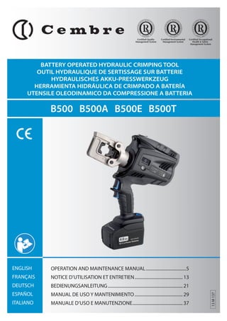
  • 1. BATTERY OPERATED HYDRAULIC CRIMPING TOOL OUTIL HYDRAULIQUE DE SERTISSAGE SUR BATTERIE 1 HYDRAULISCHES AKKU-PRESSWERKZEUG HERRAMIENTA HIDRÁULICA DE CRIMPADO A BATERÍA UTENSILE OLEODINAMICO DA COMPRESSIONE A BATTERIA B500 B500A B500E B500T ENGLISH FRANÇAIS DEUTSCH ESPAÑOL ITALIANO Certified Environmental Management System Certified Occupational Health & Safety Management System Certified Quality Management System OPERATION AND MAINTENANCE MANUAL ....................................5 NOTICE D’UTILISATION ET ENTRETIEN ........................................... 13 BEDIENUNGSANLEITUNG ................................................................... 21 MANUAL DE USO Y MANTENIMIENTO ........................................... 29 MANUALE D’USO E MANUTENZIONE ............................................. 37 13 M 137
  • 2. 2 FIG. / BILD 1 FIG. / BILD 2 FIG. / BILD 3 FIG. / BILD 4 FIG. / BILD 5 4 5 7 41 49 Connector Connecteur Kabelschuh Conector Connettore P Battery Batterie Akku Batería Batteria 62 42 Die set Matrices Presseinsätze Matrices Matrici 83 62
  • 3. FIG. / BILD 6 9 8 7 1 1 + 3 LED WORKLIGHT / ECLAIRAGE PAR LED / LED ARBEITSLICHT / LUCES LED / ILLUMINAZIONE LED 2 HEAD / TETE / KOPF / CABEZA / TESTA 3 4 OPERATING BUTTON / GACHETTE DE COMMANDE / STARTKNOPF / BOTÓN DE ACCIONAMIENTO / PULSANTE DI AZIONAMENTO 5 PRESSURE RELEASE BUTTON / GACHETTE DE DECOMPRESSION / DRUCKABLASSKNOPF / BOTÓN DESBLOQUEO PRESIÓN / PULSANTE SBLOCCO PRESSIONE 6 BATTERY / BATTERIE / AKKU / BATERÍA / BATTERIA 7 BATTERY RELEASE / DEBLOCAGE BATTERIE / AKKU ENTRIEGELUNG / DESBLOQUEO BATERÍA / SBLOCCO BATTERIA 8 TOUCH BUTTON FOR MENU SELECTION / TOUCHE POUR SELECTIONNER LE MENU / MENÜ WAHL TASTE / TECLA PARA SELECCIONAR EL MENÚ / TASTO A SFIORAMENTO PER SELEZIONE MENU 9 ECRAN / DISPLAY 10 RING FOR SHOULDER STRAP / ANNEAU POUR BANDOULIERE / TRAGERIEMENRING / ANILLO PARA CORREA / ANELLO AGGANCIO TRACOLLA 3 10 4 5 6 2
  • 4. WARNING SYMBOLS - SYMBOLES D'AVERTISSEMENT - WARNSYMBOLE - SÍMBOLOS DE ADVERTENCIA - SIMBOLI DI AVVERTENZA Tool - Outil - Werkzeug - Herramienta - Utensile – Before using the tool, carefully read the instructions in this manual. – Avant d'utiliser cet outil, lire attentivement les instructions de cette notice. – Vor Inbetriebnahme unbedingt die Bedienungsanleitung durchlesen. – Antes de utilizar la herramienta, leer atentamente las instrucciones en este manual. – Prima di utilizzare l'utensile, leggere attentamente le istruzioni riportate in questo manuale. TG.0932 – User information (Directives 2002/95/EC and 2002/96/EC), see page 46. – Information pour les utilisateurs (Directives 2002/95/CE et 2002/96/CE) voir page 46. – Information für den Benutzer (Richtlinien 2002/95/EG und 2002/96/EG) siehe Seite 46. – Informe para los usuarios (Directivas 2002/95/CE y 2002/96/CE) vease página 46. – Informazione agli utenti (Direttive 2002/95/CE e 2002/96/CE) vedere pagina 46. 4 – When operating the tool, keep hands away from the danger zone. – Au cours du sertissage, tenir les mains éloignées de la zone de travail. – Während des Verpressens nicht mit den Händen in den Pressbereich gelangen. – Durante su utilización, mantenga las manos fuera de la zona de peligro. – Durante l'utilizzo, mantenere le mani fuori dalla zona di pericolo. – Always close the tool head correctly and securely. – S'assurer toujours de la parfaite fermeture de la tête. – Immer darauf achten, dass der Kopf richtig verriegeit ist. – Asegurarse siempre de que la cabeza está correctamente cerrada. – Assicurarsi sempre della perfetta chiusura della testa. Battery -Batterie - Akku - Batería - Batteria – Never throw batteries into ( re or water. – Jamais jeter les batteries dans le feu ou dans l'eau. – Werfen Sie Akkus nicht in das Feuer oder Wasser. – Nunca tire las baterías al fuego o al agua – Mai gettare le batterie nel fuoco o in acqua. – Always recycle the batteries. – Recycler toujours les batteries. – Verbrauchte Akkus stets dem Recycling zuführen. – Reutilizar siempre las baterías. – Riciclare sempre le batterie. – Do not discard batteries into domestic refuse or waste disposal. – Ne pas jeter de batteries dans une poubelle ou autre lieu non prévu à cet e; et. – Verbrauchte Akkus nicht in den Hausmüll werfen. – No tirar las baterías al cubo de basura o lugar parecido. – Non buttate le batterie fuori uso nei cestini della spazzatura o luoghi simili.
  • 5. 1. GENERAL CHARACTERISTICS (1) Directive 2006/42/EC, annexe 1, point 1.7.4.2 letter u) LpA = weighted continuous acoustic pressure level equivalent. LpCPeak = maximum value of the weighted acoustic displacement pressure at the work place. LWA = acoustic power level emitted by the machine. (2) (Directive 2006/42/EC, annexe 1, point 2.2.1.1) Weighted root mean square in frequency of the acceleration the upper limbs are exposed to for each biodynamic reference axis. Tests carried out in compliance with the indications contained in UNI ENV 25349 and UNI EN 28662 part 1st Standards, and under operating conditions much more severe than those normally found. 5 ENGLISH B500 B500E B500T B500A Application range suitable for installing electrical compression connectors on conductors up to 240 mm2 (500 MCM). Rated crimping force kN (USA ton) 63 (7.1) Minimum crimping force kN (USA ton) 60 (6.75) Minimum operating pressure bar (psi) 661 (9587) Dimensions (ref. to Fig. 7) mm (inches) 300x343x83 (11.8xx13.5x3.3) Weight with battery kg (lbs) 4,2 (9.2) Motor V DC 18 Operating temperature °C (°F) -15 to +50 (+5 to +122) Recommended oil AGIP ARNICA 32 or equivalents. Operating speed twin speed operation and automatic switching from a rapid advancing speed of the ram to a slower, more powerful crimping speed. Safety maximum pressure valve. Rechargeable battery V / Ah / Wh 18 / 4.0 / 72 Type CB1840L (Li-Ion) Weight kg (lbs) 0,66 (1.45) Battery charger type EU UK ASC30-36 27044000 27045000 Input AUS/NZ 27047000 USA/CAN 27046000 V / Hz 220 - 240 / 50 - 60 115 / 60 W 85 Acoustic noise (1) LpA dB (A) 73 LpCPeak dB (C) 94.5 LWA dB (A) 79 Vibration (2) m/s2 0.575 max.
  • 6. WARNING 6 ENGLISH Do not use the tool for purposes other than those intended by Cembre. The operator should concentrate on the work being performed and be careful to maintain a balanced working position. Before starting work on electrical equipment, please ensure that either there are no live parts in the immediate working area or that precautions are taken for working near live parts in accordance with EN50110-1. Do not use this tool on or near energised conductors without proper personal protective equipment. Failure to observe this warning could result in severe injury or death. The tool is unsuitable for continuous use and should be allowed to cool down following uninterrupted, successive crimping operations; for instance, having exhausted a fully charged battery in one session, delay battery replacement for a few minutes. Protect the tool from rain and moisture. Water will damage the tool and battery. Electro-hydraulic tools should not be operated in pouring rain. 2. INSTRUCTIONS FOR USE IMPORTANT: In order to avoid damaging the tool, do not operate it at maxi-mum pressure, without dies inserted in the head. The part reference includes the following (Ref. to Fig. 8 page 45): A - Hydraulic crimping tool. B - Li-Ion rechargeable battery (2 pcs). C - Battery charger (model depends on the tool version). D - Shoulder strap. E - Plastic carrying case. 2.1) Preparation The tool can be easily carried using either the handle or the shoulder strap attached to ring (10) (Ref. to Fig. 6). Before starting any work, check the battery charge (Ref. to § 2.8) and recharge if necessary, following the instructions in the battery charger user manual.
  • 7. To replace the battery, remove it by pressing the release button (7) (Ref. to Fig. 1), then insert the new battery, sliding it into the guides until it locks. The display shows the operational parameters of the tool; to customise them proceed as described in § 2.7. Select the appropriate die set for the connector. Open the latch (41) and release the upper die holder (42). Insert one die into the upper die holder (42) until locked by the ball (83) and one die into the lower die support (49) until locked by the spring clips (62). Close the head. Insert the conductor into the connector (Ref. to Fig. 3). Position the connector between the dies and ensure the correct location of the crimp (Ref. to Fig. 4). 7 ENGLISH terminal connector 1 2 3 1 2 1 3 2 3 conductor conductor NOTE: when more compression is required, proceed according to the sequence and direction indicated in the > gure. Ensure that the latch and the upper die holder are fully secured, otherwise damage may occur during tool operation. 2.2) Die advancement Press operating button (4) (Ref. to Fig. 4) to activate the motor-pump and advance the lower die. To halt the advancement, release operating button (4) and the motor will cut out. Make sure the dies are exactly positioned on the desired crimp point otherwise re-open dies following instructions as per § 2.4 and reposition the connector. 2.3) Compression By keeping operating button (4) pressed, the motor continues to operate: the ram will gradually move forward until the two dies touch. The motor will stop automatically when the set pressure and the developed force have been reached. To perform proper compression, press and hold the operating button (4) until the motor stops automatically.
  • 8. 3 Fm 8 ENGLISH ERROR 3 Ï Ð Ï Ð Ï Ð Ï ÐÏ ÐÏ Ð Ï Ð Ï Ð Ï Ð = 60.0 kN Fp = 58.3 kN Pm = 661 bar Pp= 485 bar Fm = 60.0 kN OK Pm = 661 bar OK Ï Ð 3 3 SEC. NOTE: To display the momentary force or pressure during the work cycle, select the appropriate display from the menu (Ref. to § 4). When the operating button is released before the motor stops automati-cally, the display will show the peak force (Fp) or the peak pressure (Pp) reached at that instant. To complete the work, press the operating button again until the motor stops automati-cally; the display will show the maximum force or pressure reached followed by ‘OK’ to con rm correct operation. The display ‘ERROR’, combined with a beep and the LEDs ! ashing, indicates an incorrect crimping procedure caused by the work cycle being interrupted before the control parameters (force/pressure) of the tool are reached. This error appears when the pressure release button has been operated and the tool has already reached a pressure ≥ 200 bar. In this case, repeat the compression by pressing and holding the operating button until the motor stops automatically. 2.4) Release of dies By operating the pressure release button (5) (Ref. to Fig. 4), the ram will retract and open the dies. 2.5) LED Worklights Whilst the tool is in operation, the compression area is illuminated by two high luminosity LED Worklights that switch o? automatically at the end of the cycle. The LED Worklights can be disabled by following the procedure described in § 4.2. 2.6) Head rotation For ease of operation, the tool head can rotate through 180°, allowing the operator to work in the most comfortable position. Do not attempt to rotate the head when the hydraulic circuit is pressurised. 2.7) Capacitive touch button for menu selection This button is located under the display and allows selection of various screens (Ref. to § 4); it only works when the display is on. Wearing gloves or using other objects may inhibit the operation of the button, therefore use a bare nger to apply only a light touch. Do not apply pressure to or stab at the touch button, a light touch using a bare # nger is su$ cient. The command pulse is sent when the # nger releases the button.
  • 9. 2.8) Battery status The battery is equipped with LED indicators that indicate the remaining battery life at any time by pressing the adjacent button (P) (Ref. to Fig. 5): 4 LEDs illuminated: fully charged 2 LEDs illuminated: 50 % capacity 1 LED flashing : minimum charge, replace the battery. With the battery inserted into the tool, the remai-ning 9 ENGLISH 3 Ï Ð Ï Ð Ï Ð Ï 3 max. ÐÏ ÐÏ Ð Ï Ð Ï Ð min. Ï Ð BATTERY Ï 3 Ð Ï Ð Ï Ð Ï Ð BATTERY BATTERY battery life can also be checked on the display, via touch button selection (Ref. to § 4). The screen shown alongside indicates that the battery Vage has dropped below a minimum safety threshold; under these conditions the tool will not start, and it is necessary to recharge or replace the battery. The approximate time to fully recharge a battery is about 80 minutes. After each working cycle, and after the extraction of the battery from the tool, an integrated battery cut-off device will operate after 70 s approx. Then the LED nearest to button (P) will ! ash 5 times each 14 s approx. The battery will be reactivated when it is reintroduced into the tool and the operating button is pressed. 2.9) Using the battery charger Carefully follow the instructions in the battery charger user manual. 3. MAINTENANCE The tool is robust, completely sealed, and requires very little daily maintenance. Compli-ance with the following points, should help to maintain its optimum performance: 3.1) Thorough cleaning Dust, sand and dirt are a danger for any hydraulic device. Every day, after use, the tool must be wiped with a clean cloth taking care to remove any residue, especially close to pivots and moveable parts. Do not use hydrocarbons to clean the rubber parts. 3.2) Storage case When not in use, the tool should be stored and transported in the plastic case, to prevent damage. The case, type VAL P35, is suitable for storing the tool, the accessories and up to 20 die sets and pre-prepared compression connectors. VAL P35: Size 500x480x128 mm (19.7x18.9x5.0 inches). Weight 3,1 kg (6.8 lbs).
  • 10. 4. DISPLAY 10 ENGLISH The OLED display switches on automatically when the operating or pressure release but-tons are pressed, and o? after 60 seconds of non-operation. The display shows: - The main operational parameters of the tool processed by the circuit board, such as peak pressure or force reached. - Information on the condition of the tool, such as the charge level, the battery tem-perature and maintenance requirements. - Any operational or procedural ERRORS. Use the touch button (8) to navigate through the menu screens to manage INFORMA-TION AND SELECTION: 4.1) INFORMATION SCREENS: display a pre determined parameter which will then appear each time the tool is started and during the entire work cycle. Fm = 60.0 kN Fp = 24.5 kN Pm = 661 bar Pp = 312 bar Fm = 6.75 ton Fp = 2.75 ton Pm = 9587 psi Pp = 4525 psi BATTERY 1000 -19000 B500 3 NR 13AJ002 Ï Ð Fm: Minimum set force, expressed in kN. Fp: Peak force reached, expressed in kN, (screen as factory setting) Pm: Minimum set pressure, expressed in bar. Pp: Peak pressure reached, expressed in bar. Fm: Minimum set force, expressed in US tons. Fp: Peak force reached, expressed in US tons. Pm: Minimum set pressure, expressed in psi. Pp: Peak pressure reached, expressed in in psi. Battery charge level. No. of cycles performed. No. of cycles before scheduled recommended maintenance. Cembre logo, tool model. tool serial no.
  • 11. 3 BATTERY Ï Ï Ð 11 ENGLISH LED 3 OFF Ï Ð Ï Ð Ð Ï ÐÏ ÐÏ Ð Ï Ð Ï Ð LED ON LED OFF LED ON Ï Ð LOW BATTERY: replace the battery. NOTE: when the battery Vage falls below a minimum safety threshold, the tool will not start; although it is still possible to end the work cycle in progress. BATTERY TEMPERATURE HIGH: remove the battery and wait until it cools down. NO. OF CYCLES TO MAINTENANCE REACHED: 20001 the tool continues to work however, it is recommended that it is sent to Cembre for a complete overhaul (see § 5). NOTE: this screen, together with a beep, will reappear when the tool has been RESET idle for 30 seconds. 3 Ð Ï Ð Ï Ð Ï ÐÏ ÐÏ Ð BATTERY Ï Ð RESET SW:S1J41AH Ï Ð Ï Ð Ï Ð Ï ÐÏ ÐÏ Ð Ï Ð Ï Ð 3 SEC. To make a selected screen operational and appear at each start-up of the tool, operate the touch button for at least 3 seconds; a continuous beep will con rm the setting. The capacitive menu selection button may not work if touched using objects or when wearing gloves, therefore always operate it using a bare # nger. 4.2) SELECTION SCREENS: control parameters that cannot be set as automatic upon start-up of the tool, can be changed by operating the touch button: Enabling/disabling the LED Worklights (factory setting LED ON) When the screen is dis-played, touch the button for at least 3 seconds to deactivate for reactivate operation of the LED Work-lights during tool use; a continuous beep will con- rm the setting. Return to original factory settings / ( rmware version When the ‘RESET’ screen is displayed, return the tool to its factory setting by operating the touch button for at least 3 seconds; a beep will con rm the setting. The RESET screen also shows the rmware version of the circuit board. 4.3) WARNINGS: these appear during operation and notify the operator of the status of the tool:
  • 12. 4.4) ERRORS: these appear during operation, combined with a beep and J ashing LED Worklights, to notify the operator of procedural or operational errors. ENGLISH Message Error description Solution Ï ERROR Ð Ï 12 ÐÏ Ï Ð 003 ÐÏ Ð Ï Ð The pressure release button (5) was pressed before the control parameters were reached (Force/ Pressure). Repeat the work cycle and wait for the motor to stop automatically. 001 Ï Ð 002 Abnormal power consumption of the motor for more than 3 seconds. The tool stops. Wait for the display to turn o? (60 sec.) or remove and re-insert the battery, then re-start the tool. If the error occurs frequently, contact Cembre. Ï Ð Ï Ð 002 Ï Ð Ï Ð Output Vage of the pressure trans-mitter is out of the pre-set range. Repeat the work cycle; if the error occurs frequently, contact Cembre. Ï Ð Ï ÐÏ Ð 003 Ï Ð 004 Ï Ð Failure to reach the set pressure within 30 seconds of continuous operation of the machine. Repeat the work cycle; if the error occurs frequently, contact Cembre. Ï Ð Ï ÐÏ ÐÏ Ð 004 Ï Ð Overcharging of the battery with protection tripping. The tool stops. Wait for the display to turn o? (60 sec.) or remove and re-insert the battery, then re-start the tool. If the error occurs frequently, contact Cembre. Error screens are displayed for about 30 seconds before being reset, but will display repeatedly in the event of permanent anomalies. 5. RETURN TO Cembre FOR OVERHAUL In the case of a breakdown, contact your local Agent who will advise you on the problem and give you the necessary instructions on how to dispatch the tool to our nearest service Centre; if possible, attach a copy of the Cembre Test Certi cate supplied with the tool or, if no other references are available, indicate the approximate purchase date and the tool serial number.
  • 13. 1. CARACTERISTIQUES GENERALES 13 B500 B500E B500T B500A Domaine d'application: conçue pour le sertissage des connecteurs électriques jusqu' à 240 mm2 (500 MCM) Force nom. de sertissage kN (USA ton) 63 (7.1) Force min. de sertissage développée kN (USA ton) 60 (6.75) Pression min. de travail bar (psi) 661 (9587) Dimensions (voir Fig. 7) mm (inches) 300x343x83 (11.8xx13.5x3.3) Poids avec batterie kg (lbs) 4,2 (9.2) Moteur V DC 18 Température de fonction-nement: °C (°F) -15 à +50 (+5 à +122) Huile recommandée: AGIP ARNICA 32 ou équivalents. Avance rapide: l’outil passe automatiquement de la vitesse rapide d’appro-che des matrices à la vitesse lente de sertissage. Sécurité valve de surpression. Batterie rechargeable V / Ah / Wh 18 / 4.0 / 72 Type CB1840L (LI-Ion) Poids kg (lbs) 0.66 Chargeur de batterie ASC30-36 Alimentation type EU 27044000 UK 27045000 AUS/NZ 27047000 USA/CAN 27046000 V / Hz 220 - 240 / 50 - 60 115 / 60 W 85 Bruit aérien sonore (1) LpA dB (A) 73 LpCPeak dB (C) 94.5 LWA dB (A) 79 Vibrations (2) m/s2 0.575 maxi. (1) (Directive 2006/42/CE, annexe 1, point 1.7.4.2, lettre u) LpA = niveau de pression sonore continue équivalente pondérée A sur le poste de travail. LpCPeak =niveau de pression sonore instantanée pondérée C sur le poste de travail. LWA = niveau de puissance acoustique dégagée par la machine. (2) (Directive 2006/42/CE, annexe 1, point 2.2.1.1) Valeur quadratique moyenne pondérée en fréquence de l'accélération à laquelle sont exposés les membres supérieurs pour chaque axe biodynamique de référence. Relevés réalisés suivant les indications des Normes UNI ENV 25349 et UNI EN 28662 partie 1a, dans des conditions de service largement représentatives des conditions d'emploi normales. FRANÇAIS
  • 14. AVERTISSEMENT Ne pas utiliser cet outil à des # ns di érentes que celles prévues par le constructeur. Restez bien attentif tout au long du travail, ne soyez pas distrait, ne perdez pas l’équilibre pendant l'utilisation. Avant d’entreprendre des travaux sur des équipements électriques, veuillez vous assurer qu’aucun élément aux abords de la zone de travail n’est sous tension. Dans le cas contraire, veuillez prendre les précautions nécessaires pour opérer à proximité d’éléments sous tension, en conformité avec la norme EN50110-1. Ne pas utiliser cet outil sur ou à côté de conducteurs sous tension, sans pro-tection 14 FRANÇAIS individuelle adéquate. la non observation de cette précaution peut provoquer des lesions graves ou mortelles. L’outil n’est pas conçu pour une utilisation en continu; après avoir e ectué une quantité de sertissages consécutifs à partir d’une batterie complètement chargée, au moment du remplacement de la batterie, nous suggérons d’observer une période d’arrêt pour permettre le refroidissement de l’outil. Protéger l’outil de la pluie et de l’humidité. L’eau pourrait endommager l’outil et la batterie, les outils hydro-electriques ne devraient pas être utilisés sous la pluie. 2. INSTRUCTIONS D'UTILISATION IMPORTANT: Pour éviter d’endommager l’outil, il est déconseillé de l’actionner à vide et à la pression maximale, sans avoir inséré les matrices dans la tête. L' ensemble comprend (Voir Fig. 8 page 45): A - Outil hydraulique le sertissage B - Batterie rechargeable Li-Ion (2 pcs) C - Chargeur de batterie (di? érent en fonction de la version de l'outil). D - Bandoulière. E - Co? ret de rangement. 2.1) Mise en service L’outil peut être transporté facilement grâce à sa poignée et à la bandoulière accrochée par l'anneau (10) (Voir Fig. 6). Avant de commencer toute opération, contrôler l’état de charge de la batterie (voir § 2.8) et, si nécessaire, la recharger en suivant les instructions contenues dans le manuel d’utilisation du chargeur de batteries.
  • 15. 15 FRANÇAIS Pour remplacer la batterie, la retirer en appuyant sur le mécanisme de déblocage (7) (voir Fig. 1), puis introduire la nouvelle batterie en la faisant coulisser sur les guides jusqu’au blocage complet. L’écran permet d’a{ cher les paramètres opérationnels de l’outil. Pour personnaliser ces derniers, suivre les instructions décrites au § 2.7. Choisir le couple de matrices approprié pour le type de connexion à réaliser; pour cela, consulter le catalogue. Ouvrir la tête de l'outil en écartant le levier (41), libérant ainsi le porte matrice supérieur (42)qui s'écartera complètement (Voir Fig. 2). Insérer les matrices dans leur logement respectif (Voir Fig. 2) dans le porte matrice supérieur (42) jusqu'à ce qu'il soit verrouillé par la bille (83) et dans le support de matrice inférieure (49) jusqu'à ce qu'il soit verrouillé par les ressorts (62). Refermer la tête. Insérer le conducteur dans le connecteur (Voir Fig. 3). Positionner ce dernier entre les deux matrices en alignant la zone à sertir avec l'em-preinte des matrices (Voir Fig. 4). REMARQUE : s’il est nécessaire de procéder à plusieurs sertis-sage de cosses ou de manchon, suivre la séquence et la direc-tion reportée sur l’illustration en espaçant les empreintes de façon uniforme. Avant de poursuivre les opérations, véri# er que cosse 1 2 1 3 manchon 1 2 3 2 3 conducteur conducteur la tête soit parfaitement fermée. 2.2) Avance des matrices Appuyer sur la gâchette de commande (4) (Voir Fig. 4) pour mettre en marche le grou-pe moteur pompe; les matrices commencent alors à se rapprocher du connecteur. La gâchette de commande (4) relâchée, le moteur et l'avance des matrices cessent immédiatement. S S'assurer que les matrices sont bien positionées sur la zone à sertir, sinon des-serer les matrices en suivant les instructions du § 2.4 et repositioner le connecteur. 2.3) Sertissage En maintenant pressée la gâchette de commande (4), on maintient la rotation du moteur; le piston avance progressivement jusqu'à ce que les matrices arrivent en butée l'une contre l'autre. L’outil s’arrêtera automatiquement dès qu’il aura atteint la pression de tarage et la force développée. Pour effectuer un bon sertissage, maintenir la gâchette de commande (4) pressée jusqu’à l’arrêt automatique du moteur.
  • 16. REMARQUE: Pour a{ cher la force ou la pression en temps réel, lors du cycle de travail, con gurer les écrans correspondants (voir § 4). En relâchant le bouton de démarrage avant l’arrêt automatique du moteur, l’écran a{ chera les valeurs de pic de la force (Fp) et de la pression (Pp) atteintes à ce moment. Pour terminer l’opération, ré-appuyer sur la gâchette de commande jusqu’à l’arrêt au-tomatique 3 Fm du moteur ; l’écran a{ chera la force ou la pression maximale atteinte, suivie 16 FRANÇAIS ERROR 3 Ï Ð Ï Ð Ï Ð Ï ÐÏ ÐÏ Ð Ï Ð Ï Ð Ï Ð = 60.0 kN Fp = 58.3 kN Pm = 661 bar Pp= 485 bar Fm = 60.0 kN OK Pm = 661 bar OK Ï Ð 3 3 SEC. de l’inscription « OK » indiquant que l’opération a été correctement e? ectuée. Le message « ERROR » associé à l’avertisseur sonore ainsi que le clignotement des LED indiquent que la procédure de sertissage n’a pas été correctement e ectuée en raison d’un arrêt anticipé du cycle de travail avant d’avoir atteint les paramètres réglés (force/pression) de l’outil. Ce message d’erreur s’a$ che lorsque l’opérateur appuie sur la gâchette de débloc-age pression après que l’outil ait atteint une pression ≥ 200 bar. Dans ce cas, e ectuer à nouveau le sertissage en maintenant la gâchette de commande appuyée jusqu’à l’arrêt automatique du moteur. Pour terminer l’opération, ré-appuyer sur la gâchette de commande jusqu’à l’arrêt automatique du moteur ; l’écran a$ chera la force ou la pression maximale atteinte, suivie de « OK » indiquant que l’opération a été correctement e ectuée. 2.4) Réouverture des matrices En appuyant à fond sur la gâchette de déblocage pression (5) (Voir Fig. 4), on provoque le retour du piston et par conséquent l'ouverture des matrices. 2.5) Led Lors de l’actionnement de l’outil, la zone de sertissage est éclairée au moyen de deux LED haute luminosité qui s’éteignent automatiquement à la n du cycle. Pour désactiver les LED, suivre la procédure décrite au § 4.2. 2.6) Rotation de la tête La tête de l'outil pivote de 180° par rapport au corps, permettant à l'utilisateur de travail-ler dans la meilleure position. Ne pas forcer la rotation de la tête, lorsque le circuit hydraulique est sous pression. 2.7) Touche tactile de type capacitif Cette touche est située sous l’écran et permet de sélectionner les di? érents écrans (voir § 4) ; elle fonctionne uniquement lorsque l’écran est allumé et il su{ t de l’e} eurer à mains nues. L’utilisation de gants ou d’autres objets risquerait de compromettre son activation. Ne jamais appuyer avec force sur la touche tactile, il su$ t de l’e? eurer avec un doigt, à mains nues. La commande envoie l’impulsion dès le retrait du doigt.
  • 17. 2.8) Autonomie de la batterie La batterie est équipée d’indicateurs à LED qui permettent de contrôler, à tout moment, son autonomie résiduelle en appuyant sur la touche (P) (voir Fig. 5) : 4 led allumées: autonomie maximale 2 led allumées: autonomie à 50 % 1 led clignotante: autonomie minimale, remplacer la batterie. Lorsque la batterie est insérée dans l’outil, il est possible de véri er l’autonomie résiduelle à partir de l’écran, en appuyant sur la touche tactile (voir § 4). 17 FRANÇAIS 3 Ï Ð Ï Ð Ï Ð Ï 3 max. ÐÏ ÐÏ Ð Ï Ð Ï Ð min. Ï Ð BATTERY Ï 3 Ð Ï Ð Ï Ð Ï Ð BATTERY BATTERY L’écran ci-contre indique que la batterie est déchargée et que sa tension est descendue au-dessous du seuil minimal de sécurité ; dans cette situation, l’outil ne démarre pas, il est donc nécessaire de recharger ou de remplacer la batterie. À titre indicatif, le délai de recharge complète de la batterie correspond à environ 80 min. A la # n de chaque cycle de travail comme à l’extraction de la batterie de l’outil, un dispositif électronique arrête automatiquement la batterie après environ 70 s. Pour con# rmer cette opération, la led la plus proche du bouton (P) clignotera 5 fois en 14 s (approximativement). La batterie est réactivée dès sa réintroduction dans l’outil, ou en appuyant sur le bouton d’actionnement. 2.9) Utilisation du chargeur de batterie Suivre attentivement les instructions indiquées sur le manuel. 3. ENTRETIEN L'outil est robuste, complètement scellé et ne nécessite aucune préoccupation ou attention particulier. Les recommandations qui suivent sont néanmoins souhaitables pour assurer une longévité optimum: 3.1) Nettoyage élémentaire Veiller à protéger l'outil de la poussière, du sable et de la boue qui sont un danger à tout système hydraulique. Chaque jour après utilisation, l'outil doit être nettoyé à l'aide d'un chi? on propre, tout particulièrement aux endroits de pièces mobiles. Ne jamais utiliser d’hydrocarbures pour le nettoyage des parties en caoutchouc. 3.2) Rangement Au repos, pour protéger l'outil des coups accidentels et de la poussière, il convient de le ranger dans le co? ret. Ce co? ret (type VAL P35), adapté pour contenir l'outil, ses acces-soires et 20 paires de matrices a comme dimensions: 500x480x128 mm (19.7x18.9x5.0 inches) et un poids de 3,1 kg (6.8 lbs).
  • 18. 4. ECRAN L’écran OLED s’active lors du démarrage de l’outil et se désactive automatiquement au bout de 60 secondes d’inutilisation de l’outil. L’écran permet d’a{ cher : - Les principaux paramètres opérationnels de fonctionnement de l’outil, con gurés par la carte électronique, tels que la pression ou la force développée. - Informations sur l’état de l’outil telles que le niveau de charge, la température de la batterie et besoin éventuel d’entretien. - ERREURS éventuelles de fonctionnement ou de procédure. Il est possible de se déplacer dans le menu à l’aide de la touche tactile (8) et de gérer les ÉCRANS D’INFORMATION ET DE SÉLECTION : 18 FRANÇAIS 4.1) ECRANS D’INFORMATION a{ chent à l’écran un paramètre donné qui s’a{ chera ensuite à chaque démarrage de l’outil et tout au long du cycle de travail. Fm = 60.0 kN Fp = 24.5 kN Pm = 661 bar Pp = 312 bar Fm = 6.75 ton Fp = 2.75 ton Pm = 9587 psi Pp = 4525 psi BATTERY 1000 -19000 B500 3 NR 13AJ002 Fm: force minimale de réglage, exprimée en kN Fp : Force atteinte en temps réel, exprimée en kN (écran tel que con guré par les paramètres standards d’usine) Ï Ð Pm : Pression minimale de réglage, exprimée en bar. Pp : Pression atteinte en temps réel, exprimée en bar. Fm : Force minimale développée, exprimée en tonnes (USA) Fp : Force atteinte en temps réel, exprimée en tonnes (USA) Pm : Pression minimale de réglage, exprimée en psi Pp : Pression atteinte en temps réel, exprimée en psi Niveau de charge de la batterie Nbr de cycles e? ectués. Nbr de cycles restant à e? ectuer lors de l’entretien ordinaire. logo Cembre, série outil n° de série de l’outil
  • 19. LED ON LED OFF 3 Ï Ð BATTERY Ï Ï Ð 20001 19 FRANÇAIS 3 RESET Ð Ï Ð Ï Ð Ï ÐÏ ÐÏ Ð BATTERY Ï Ð RESET SW:S1J41AH Ï Ð Ï Ð Ï Ð Ï ÐÏ ÐÏ Ð Ï Ð Ï Ð 3 SEC. Ï Ð Ï Ð Ï Une fois que l’écran présélectionné s’est a{ ché, pour le rendre opéra-tionnel Ï Ð et xe à chaque démarrage de l’outil, maintenir la touche tac-tile appuyée pendant une période prolongée (au moins 3 secondes). Un signal sonore continu con rmera la con guration e? ective. 3 Ï Ð ÐÏ ÐÏ La touche capacitive risque de ne pas fonctionner si celle-ci est e? eurée avec des objets ou des gants, appuyer sur cette touche uniquement à mains nues. 4.2) ECRANS DE SELECTION: permettent de modi er certains paramètres de Ð réglage, ils ne peuvent être con gurés de manière automatique au démarrage de l’outil ; pour les activer, il est toujours nécessaire d’appuyer sur la touche tactile. Ï Ð Activation/désactivation des LED (paramètre standard d’usine : LED ACTIVÉE) Une fois l’écran a{ ché et lors de l’utilisation de l’outil, pour le désactiver ou réac-tiver le démarrage des LED, maintenir la touche tactile appuyée pendant une pé-riode LED OFF LED ON prolongée (au moins 3 secondes). Un signal sonore continu con rmera la con- guration e? ective. Retour au paramètres d’usine de départ / Version du ( rmware. Une fois l’écran « RESET » a{ ché, maintenir la touche tactile appuyée pendant une période prolongée (au moins 3 secondes). Un signal sonore continu con rmera la con- guration e? ective. L’écran RESET a{ che également la version du rmware de la carte électronique. 4.3) AVERTISSEMENT s’a{ chent lors du fonctionnement et fournissent des informations à l’opérateur sur l’état de l’outil: BATTERIE DÉCHARGÉE : procéder à son remplacement. REMARQUE : lorsque la tension de la batterie est inférieure au seuil minimal de sécurité, l’outil ne démarre pas mais l’opérateur peut, quoiqu’il en soit, terminer le cycle de travail en cours. TEMPÉRATURE ÉLEVÉE DE LA BATTERIE : retirer la batterie et patienter jusqu’à ce qu’elle se refroidisse. UNE FOIS LE NBR DE CYCLES PREVU POUR L’ENTRETIEN ORDINAIRE EFFECTUE : l'outil continue à fonctionner, il est recommandé d’envoyer l’outil à Cembre afin de procéder à une révision complète (voir § 5). REMARQUE : cet écran, associé à un signal sonore, apparaît à nouveau au bout de 30 secondes d’inutilisation de l’outil.
  • 20. 4.4) ERREURS: apparaissent lors du fonctionnement. Lorsqu’elles sont associées à un signal sonore et lumineux, ils indiquent à l’opérateur la présence d’éventuelles erreurs de procédure ou de fonctionnement. Message Description erreur Solution Ï Ð Ï Ð Ï Ð Ï ERROR 20 FRANÇAIS ÐÏ ÐÏ Ï Ð 003 Ð Ï Ð Actionnement de la gâchette de déblocage pression (5) avant que l’outil n’ait atteint les paramètres de réglage (Force/Pression). Procéder à nouveau au cycle de travail et attendre l’arrêt automatique du moteur. 001 002 Ð Ï Ð Absorption anormale de courant de la part du moteur pendant plus de 3 secondes. L'outil s’arrête. Patienter jusqu’à l’arrêt de l’écran (60 secondes) ou retirer, puis réinsérer la batterie. Redémarrer l’outil. Si ce signal d’erreur apparaît souvent, contacter Cembre. Ï Ð Ï Ð 002 Ï Ð Ï Tension de sortie de l’émetteur de pression en dehors de l’intervalle con guré. Procéder à nouveau au cycle de travail. Si ce signal d’erreur apparaît souvent, contacter Cembre. Ï Ð Ï ÐÏ Ð 003 Ï Ð 004 Ï Ð Impossible d’atteindre la pression de tarage dans les 30 secondes à compter de l’actionnement con-tinu de l’outil. Procéder à nouveau au cycle de travail. Si ce signal d’erreur apparaît souvent, contacter Cembre. Ï Ð ÐÏ ÐÏ Ð 004 Ï Ð Surcharge de la batterie avec ac-tionnement de la protection. L'outil s’arrête. Patienter jusqu’à l’arrêt de l’écran (60 secondes) ou retirer, puis réinsérer la batterie. Redémarrer l’outil. Si ce signal d’erreur apparaît souvent, contacter Cembre. Les écrans d’erreur restent a$ chés à l’écran pendant environ 30 secondes, puis l’erreur est réinitialisée. Ils se présentent à nouveau en cas d’anomalie permanente. 5. ENVOI EN REVISION A Cembre En cas de dysfonctionnement de l'appareil, merci de vous adresser à notre Agent Régional qui vous conseillera et le cas échéant vous donnera les instructions néces-saires pour envoyer l'outil à notre Centre de Service le plus proche. Dans ce cas, join-dre une copie du Certi cat d'Essai livré par Cembre avec l'outil ou, à défaut d'autres éléments de référence, indiquer la date d'achat approximative et numéro de série.
  • 21. Anwendungsbereich Geeignet zum Verpressen von Verbindern und Kabelschuhen Nennpreßkraft kN (USA ton) 63 (7.1) Minimale Preßkraft kN (USA ton) 60 (6.75) Minimale Arbeitsdruck bar (psi) 661 (9587) Abmessungen (siehe Bild 7) mm (inches) 300x343x83 (11.8xx13.5x3.3) Gewicht inkl. Akku kg (lbs) 4,2 (9.2) Motor V DC 18 Betriebstemperatur: °C (°F) -15 bis +50 (+5 bis +122) Empfohlenes Öl: AGIP ARNICA 32 oder ähnliches Kolbenvorschub: Sicherheit: Überdruckventil Wiederau adbarer Akku V / Ah / Wh 18 / 4.0 / 72 Typ CB1840L (Li-Ionen) Gewicht kg (lbs) 0,66 (1.45) Akkuladegerät ASC30-36 Eingangspannung Lärmschutzbestimmung (1) LpA dB (A) 73 LpCPeak dB (C) 94.5 LWA dB (A) 79 Vibrationen (2) m/s2 0.575 max. 21 DEUTSCH 1. ALLGEMEINE EIGENSCHAFTEN B500 B500E B500T B500A bis zu einem Querschnitt von max. 240 mm2 (500 MCM). Das Werkzeug ist mit einer Doppelkolbenhydraulik aus-gerüstet, die ein schnelles Zusammenfahren der Pressein-sätze ermöglicht. Beim Beginn des Pressvorganges wird auf den langsameren Arbeitshub umgeschaltet. Typ EU 27044000 UK 27045000 AUS/NZ 27047000 USA/CAN 27046000 V / Hz 220 - 240 / 50 - 60 115 / 60 W 85 (1) Richtlinie 2006/42/EG, Anhang 1, Nummer 1.7.4.2, Buchstabe u) LpA = konstanter Lärmpegel entsprechend Gewichtung A am Arbeitsplatz LpCPeak = höchster Lärmpegel entsprechend Gewichtung C am Arbeitsplatz LWA = Lärmbelastung des Geräts (2) Richtlinie 2006/42/EG, Anhang 1, Nummer 2.2.1.1) Der Wert bezieht sich auf Messungen, entsprechend der Normen UNI ENV 25349 und UNI EN 28662 Teil 1 unter re-präsentativen Bedingungen, bei dem der durchschnittliche Messwert an den oberen Teilen den Wert nicht überschritt.
  • 22. 22 HINWEISE Verwenden Sie das Akkuwerkzeug ausschließlich für den vom Hersteller vorgesehenen Anwendungszweck. Arbeiten Sie konzentriert und lassen Sie sich während des Einsatzes nicht ablenken und nehmen zur Arbeit eine sichere und standfeste Arbeitsposition ein! Vor Beginn der Arbeiten an elektrischen Anlagen ist sicherzustellen, dass sich keine spannungsführenden Teile in unmittelbarer Nähe des Arbeitsbereiches be# nden. Ansonsten muss durch geeignete Maßnahmen entsprechend der EN 50110-1 der Arbeitsbereich abgesichert werden. Dieses Werkzeug nicht ohne ausreichende Schutzmaßnahmen an oder in der Nahe von stromführenden Leitungen verwenden! Eine Nichtbeachtung von den Schutzmaßnahmen kann zu Verletzungen oder zum Tode führen. Die Akkuwerkzeuge sind nicht für einen Dauereinsatz geeignet. Wenn ein voll geladener Akku durch hintereinander ausgeführte Verpressungen getauscht werden muss, empfehlen wir vor dem Akkuwechsel das Werkzeug eine angemessene Zeit abkühlen zu lassen Das Werkzeug vor Regen und Feuchtigkeit schützen. Wasser könnte das Werkzeug und den Akku beschädigen. Elektrohydraulische Werkzeuge sollten nicht im Regen eingesetzt werden. 2. BEDIENUNGSHINWEISE WICHTIG: Um Schäden an dem Werkzeug zu vermeiden, sollte es nicht mit Maximaldruck ohne Pressmaterial und ohne eingesetzte Presseinsätze im Presskopf betätigt werden. Zum Lieferumfang unter dieser Bezeichnung gehören folgende Teile (Bild 8 Seite 45): A - Hydraulisches Akkupresswerkzeug B - 2 Stück wiederaufladbare Li-Ion Akkus C - Ladegerät (entsprechend der Länderkon guration) D - Trageriemen E - Kunststo? ko? er 2.1) Vorbereitung Das Werkzeug kann bequem am Gri? oder mit dem Trageriemen der am Ring (Bild 6 T.10) befestigt ist transportiert werden. ÜberprüfenSie vor jedem Arbeitsvorgang den Ladezustand der Akkus (siehe Pkt. 2.8) und laden Sie bei Bedarf die Akkus entsprechend den Anweisungen in der Bedienungsanleitung des Akkuladegerätes auf. DEUTSCH
  • 23. 23 DEUTSCH Drücken Sie für den Akkuaustausch auf die Entriegelung (7) (siehe Bild 1) und führen Sie den neuen Akku bis zum Einratsen ein. Auf dem Display werden die Betriebsparameter des Werkzeuges angezeigt. Sie können laut der Bedienungsanleitung Pkt. 2.7 persönliche Einstellungen vornehmen. Passenden Presseinsatz auswählen. Öffnen Sie den Kopf der Akkupresse am Haken (41) und der obere Presseinsatzhalter (42) kann weit geöffnet werden (siehe Bild 2). Setzen Sie die Presseinsätze in die vorgesehene Halterung ein (siehe Bild 2): den oberen Presseinsatz in den Presseinsatzhalter (42) bis die Kugel (83) einrastet, den unteren in den Presseinsatzhalter (49) bis er in den Federn (62) einrastet. Schließen Sie den Presskopf. Den zu verpressenden Leiter in den Verbinder oder Kabelschuh einlegen (siehe Bild 3). Positionieren Sie den Verbinder oder Kabelschuh an der vorgeschriebenen Position am Presseinsatz (siehe Bild 4). ANMERKUNG: Beim Pressen von Kabelschuhen oder Ver-bindern gehen Sie bei mehreren erforderlichen Pressvorgängen gemäß der in der Abbildung angegebenen Reihenfolge und Richtung vor. Kabelschuh 1 2 1 3 Verbinder 1 2 3 2 3 Leiter Leiter Vor Inbetriebnahme des Werkzeug muss der Kopf vollständig geschlossen sein, sonst kann es zu Beschä-digungen kommen. 2.2) Positionierung Durch Drücken des Startknopfes (4) (siehe Bild 4) beginnen Motor und Pumpe zu arbeiten und die Preßeinsätze nähern sich dem Verbinder oder Kabelschuh. Sobald der Startknopf (4) wieder losgelassen wird, halten Motor und Kolben sofort an. S Die Presseinsätze müssen in die gewünschte Position am Verbinder oder Kabel-schuh gebracht werden. Sollte diese nicht korrekt sein, muss das Werkzeug entsprechend Pkt. 2.4 geö net werden und es kann neu positioniert werden. 2.3) Verpressung Wird der Startknopf (4) weiter gedrückt, fahren die Presseinsätze langsam aufeinander zu und die Verpressung wird durchgeführt. Das Werkzeug hält bei Erreichen des eingestellten Druckes und der erreichten Kraft automatisch an. Halten Sie für einen korrekten Pressvorgang den Startknopf bis zur automatischen Abschaltung des Motors gedrückt.
  • 24. ERROR 24 Fm 3 3 Ï Ð Ï Ð Ï Ð Ï ÐÏ ÐÏ Ð Ï Ð Ï Ð Ï Ð = 60.0 kN Fp = 58.3 kN Pm = 661 bar Pp= 485 bar Fm = 60.0 kN OK Pm = 661 bar OK Ï Ð DEUTSCH 3 3 SEC. ANMERKUNG: Zum Anzeigen der aktuellen Kraft-oder Presswerte während des Arbeitszyklus stellen Sie bitte die entsprechenden Ansichten ein (siehe Pkt. 4). Wenn Sie den Startknopf vor der automa-tischen Abschaltung des Motors loslassen, zeigt das Display die zu diesem Zeitpunkt erreichte Maximal-kraft (Fp) oder den Maximaldruck (Pp) an. Um den Arbeitsvorgang zu beenden, drücken Sie erneut bis zur automatischen Abschaltung des Motors auf den Startknopf. Das Display zeigt nun die maximal erreichten Kraft- oder Druckwerte, gefolgt von OK an, was den korrekten Vorgang bestätigt. Die Meldung ERROR in Verbindung mit einem akustischen Signal und blinkenden LED-Anzeigen deutet daraufhin, dass der Pressvorgang aufgrund eines vorzeitigen Abbruchs des Arbeitszyklus vor Erreichen der Einstellparameter (Kraft/Druck) des Werkzeuges fehlerhaft war. Dieser Fehler tritt auf, wenn der Druckablassknopf gedrückt wird und das Werkzeug einen Druck ≥ 200 bar erreicht hat. Wiederholen Sie den Pressvorgang in diesem Fall und halten Sie den Startknopf bis zur automatischen Abschaltung des Motors gedrückt. 2.4) Ö; nen der Presseinsätze Drücken Sie kräftig den Druckablassknopf (5) (siehe Bild 4). Dadurch fährt der Kolben zurück und die Presseinsätze geben den Kabelschuh / Verbinder frei. 2.5) LED Während der Betätigung des Werkzeugs wird der Pressbereich von zwei LED-Anzeigen mit hoher Helligkeit ausgeleuchtet, die sich am Zyklusende automatisch abschalten. Die LED Leuchten können wie unter Pkt. 4.2 beschrieben deaktiviert werden. 2.6) Drehbewegung des Kopfes Das Werkzeug ist mit einem Kopf ausgerüstet, der um 180° drehbar ist und somit ein komfortables Arbeiten ermöglicht. Der Kopf sollte keinesfalls in eine andere Position gedreht werden, während die Akkupresse unter Druck steht. 2.7) Kapazitive Taste Die Taste be ndet sich unterhalb des Displays und ermöglicht die Auswahl verschiedener Ansichten (siehe Pkt. 4). Sie funktioniert nur bei eingeschaltetem Display und es reicht sie mit bloßen Fingern leicht zu berühren. Das Tragen von Handschuhen bzw. andere Gegenstände könnten die Betätigung verhindern. Drücken Sie niemals fest auf die kapazitive Taste. Es reicht aus, sie sanft mit einem Finger und mit bloßen Händen zu berühren. Der Steuerungsimpuls wird beim Loslassen gesendet.
  • 25. 2.8) Akkuladung Die Akku ist mit LED-Anzeigen ausgestattet, die jederzeit über die verbleibende Akku-laufzeit Auskunft gibt, indem man auf die Taste (P) (siehe Bild 5) drückt: 4 LED eingeschaltet: Maximale Ladung 2 LED eingeschaltet: Ladung zu 50 % 1 LED blinkend: Minimale Ladung, Akku austauschen bzw. auJ aden. Wenn sich der Akku im Werkzeug be ndet, kann man die verbleibende Akkulaufzeit auch auf dem Display ablesen, indem man die kapazitive Taste berührt (siehe Pkt. 4). 25 DEUTSCH 3 Ï Ð 3 max. Ï Ð Ï Ð Ï ÐÏ ÐÏ Ð Ï Ð Ï Ð min. Ï Ð BATTERY Ï 3 Ð Ï Ð Ï Ð Ï Ð BATTERY BATTERY Diese Ansicht zeigt an, dass der Akku leer und die Spannung auf das Mindestsicherheitsniveau gesunken ist. Unter diesen Bedingungen kann das Werkzeug nicht in Betrieb genommen werden. Laden Sie den Akku auf oder tauschen Sie ihn aus. Ein vollständiger Ladevorgang eines leeren Akkus dauert etwa 80 Minuten. Nach jedem Arbeitszyklus und wie auch nach der Entfernung des Akkus schaltet es durch die eingebaute Elektronik nach ca. 70s automatisch ab. Als Bestätigung des Vorganges wird die LED bei der Taste (P) 5-mal hintereinander inner-halb von ca. 14s blinken. Durch das Einführen des Akkus in das Werkzeug wird der Akku wieder aktiviert oder durch die Betätigung des Startknopfes. 2.9) Verwendung des Ladegerätes Die in der Bedienungsanleitung gegebenen Hinweise sind zu beachten. 3. WARTUNG Das Werkzeug ist robust und benötigt keine spezielle PJ ege. Zur Erhaltung der Garantieansprüche beachten Sie folgende Hinweise: 3.1) P ege Dieses hydraulische Werkzeug sollte vor starker Verschmutzung geschützt werden, da dies für ein hydraulisches System gefährlich ist. Jeden Tag nach der Arbeit sollte das Werkzeug mit einem Tuch von Schmutz und Staub gereinigt werden, besonders die beweglichen Teile. Verwenden Sie keine Kohlenwassersto? e (z.B. Teilereiniger, Bremsenreiniger) zum Reinigen der Gummiteile. 3.2) Lagerung Wenn das Werkzeug nicht benötigt wird, sollte es in dem Kunststo? ko? er gelagert werden und ist somit gegen Beschädigungen wie Stoß und Staub geschützt. Der Kunststoffkoffer Typ VAL P35 hat folgende Abmessungen: 500x480x128 mm (19.7x18.9x5.0 inches) und ein Gewicht von 3,1 kg (6.8 lbs.). Er ist geeignet zum Lagern vom Werkzeug und Zubehör sowie auch 20 Paar Presseinsätzen.
  • 26. 4. DISPLAY Das mit der OLED-Technologie ausgestattete Display wird mit dem Starten des Werkzeuges aktiv und wird nach etwa 60 Sekunden, in denen das Werkzeug nicht benutzt wird, au-tomatisch 26 inaktiv. Auf dem Display ird folgendes angezeigt: - die wichtigsten Betriebsparameter wie Druck oder erzeugte Kraft die von der Elektronik erfasst wurden - Informationen über den Zustand des Werkzeuges wie Ladezustand und Temperatur des Akkus und Wartungsempfehlungen - mögliche Fehler über Werkzeug oder den Arbeitsvorgang Mit Hilfe der kapazitiven Taste (8) kann man im Menü navigieren und die INFORMATIONS-UND AUSWAHLANSICHTEN VERWALTEN: 4.1) INFORMATIONSANSICHTEN: Damit kann ein bestimmter Parameter auf dem Display angezeigt werden, der anschließend bei jedem Starten des Werkzeuges und während des gesamten Arbeitszyklus erscheint. Fm = 60.0 kN Fp = 24.5 kN Pm = 661 bar Pp = 312 bar Fm = 6.75 ton Fp = 2.75 ton Pm = 9587 psi Pp = 4525 psi BATTERY 1000 -19000 B500 3 NR 13AJ002 Ï Ð Fm: Mindestpresskraft in kN Fp: Erreichter Mindestpresskraft in kN (Werkseinstellung) Pm: Mindestdruck in bar Pp: Erreichter Momentandruck in bar Fm: Mindestpresskraft in USA Tonnen Fp: Erreichter Mindestpresskraft in USA Tonnen Pm: Mindestdruck in psi Pp: Erreichter Momentandruck in psi Ladezustand des Akkus Anzahl der ausgeführten Zyklen Anzahl der ausstehenden Zyklen bis zur normale Wartung Cembre-Logo, Werkzeugtyp Seriennummer des Werkzeuges DEUTSCH
  • 27. 3 Die kapazitive Taste funktioniert womöglich nicht, wenn sie mit Gegen-ständen BATTERY Ï Ï Ð 20001 27 DEUTSCH Wenn Sie einen gewählten Bildschirm bei jedem Starten des Werkzeuges fest anzeigen möchten, berühren Sie länger (ca. 3 Sekunden) die kapazitive Taste, woraufhin ein akustisches Signal die erfolgte Einstellung bestätigt. 3 oder Handschuhen berührt wird. Benutzen Sie immer die bloßen AKKU LEER: Akku austauschen ANMERKUNG: Wenn die Batteriespannung unter das Mindest-Sicherheits-niveau sinkt, startet das Werkzeug nicht mehr. Man kann jedoch den laufenden Zyklus beenden ERHÖHTE AKKUTEMPERATUR: Die Akku entnehmen und abkühlen lassen DIE FÜR DIE NORMALE WARTUNG VORGESEHENE ANZAHL AN ZYKLEN IST ERREICHT: Das Werkzeug funktioniert weiterhin, es wird aber empfohlen, es für eine Wartung an Cembre zu schicken (siehe Pkt. 5). ANMERKUNG. Diese Ansicht erscheint zusammen mit einem akustischen Signal immer nach 30 Sekunden, in denen das Werkzeug nicht verwendet wird. 3 RESET Ð Ï Ð Ï Ð Ï ÐÏ ÐÏ Ð BATTERY Ï Ð RESET SW:S1J41AH Ï Ð Ï Ð Ï Ð Ï ÐÏ ÐÏ Ð Ï Ð Ï Ð 3 SEC. 3 sek. LED OFF Ï Ð Ï Ð Ð Ï ÐÏ ÐÏ Ð Ï Ð Ï Ð LED ON LED OFF LED ON Ï Ð 3 sek. Hände. 4.2) AUSWAHLANSICHTEN: Damit kann man einige Einstellparameter verändern. Sie können nicht automatisch beim Starten des Werkzeuges eingestellt werden, sondern sind nur mit Hilfe der kapazitiven Taste abrufbar: Aktivierung/Deaktivierung der LED-Anzeigen (Werkseinstellung: LED ON) Berühren Sie bei angezeigter Ansicht länger (mindestens 3 Sekunden) die kapazitive Taste, um das Angehen der LED-Anzeigen während der Verwendung des Werkzeug es zu aktivieren oder zu deaktivieren. Ein akustisches Signal zeigt die erfolgte Einstel-lung an. Rückkehr zu den ursprünglichen werkseitigen Einstellungen/Firmware-Version. Berühren Sie bei angezeigter RESET-Ansicht länger (mindestens 3 Sek.) die kapazitive Taste, um das Werkzeug zu den ursprünglichen werkseitigen Einstellungen zurückzuführen. Ein akustisches Signal zeigt die erfolgte Einstellung an. Die RESET-Einstellung zeigt außerdem die Firmware-Version der Elektronikkarte an. 4.3) WARNHINWEISE: Sie erscheinen während des Betriebes und informieren den Bedie-ner über den Zustand des Werkzeuges:
  • 28. 4.4) FEHLERMELDUNGEN: Sie erscheinen während des Betriebes in Verbindung mit einem akustischen Signal und einem Blinken der LED-Anzeigen. Damit wird der Anwender über mögliche Betriebs- und Arbeitsfehler informiert. Meldung Beschreibung des Fehlers Lösung Ï Ð Ï ERROR Ï Ï Ð Ð Ï Ï Ð 001 Ð 002 ÐÏ Ï Ï Ð 003 ÐÏ ÐÏ 002 Ï Ð Ï Ð Ð Ï Ð Betätigung des Druckablassknop-fes (5) vor Erreichen der eingestel-lten ParameterKraft/Druck). Wiederholen Sie den Arbeitszyklus und warten Sie bis zur automatischen Abschaltung des Motors. Sehr hohe Stromaufnahme des Motors innerhalb von 3 Sekunden. Das Werkzeug bleibt stehen. Warten Sie bis das Display inaktiv wird (60 Sek) oder entnehmen Sie den Akku und führen Sie ihn wieder ein. Starten Sie das Werkzeug erneut. Wenden Sie sich an Cembre, falls dieser Fehler wiederholt auftritt. Die Ausgangsspannung des Drucksensors liegt nicht im fest-gelegten Bereich. Wiederholen Sie den Arbeitszyklus. Wenden Sie sich an Cembre, falls der Fehler wiederholt auftritt. Ð 003 Ï Ð 004 DEUTSCH Ï Ð 28 Der eingestellte Pressdruck wurde innerhalb von 30 Sek. nicht er-reicht, seit dem Einschalten des Werkzeuges. Wiederholen Sie den Arbeitszyklus. Wenden Sie sich an Cembre, falls der Fehler wiederholt auftritt. Ï Ð Ï ÐÏ ÐÏ Ð 004 Ï Ð Akkuüberlastung und Auslösung der Schutzvorrichtung. Das Werkzeug hält an. Warten Sie bis das Display inaktiv wird (60 Sek) oder entnehmen Sie den Akku und führen Sie ihn wieder ein. Starten Sie das Werkzeug erneut. Wenden Sie sich an Cembre, falls dieser Fehler wiederholt auftritt. Die Fehleransichten werden auf dem Display etwa 30 Sekunden lang angezeigt, dann wird der Fehler zurückgesetzt. Bei permanenter Störung werden sie erneut angezeigt. 5. EINSCHICKEN AN Cembre ZUR ÜBERPRÜFUNG Sollten am Gerät Fehler auftauchen, wenden Sie sich bitte an unsere Gebietsvertretung, welche Sie gerne beraten und Ihnen alle nötigen Informationen zum Einschicken des Gerätes an unseren Hauptsitz geben wird. Wenn vorhanden, legen Sie bitte dem Gerät das von Cembre mitgelieferte Überprüfungszerti kat bei. Bei Ermangelung dieser Informationen geben Sie bitte an, wann Sie das Gerät erworben haben.
  • 29. Campo de aplicación: para la instalación de conectores eléctricos por compresión Fuerza nomin. de compresión kN (USA ton) 63 (7.1) Fuerza mínima desarrollada kN (USA ton) 60 (6.75) Presión mínima de trabajo bar (psi) 661 (9587) Dimensiones (Ref. a Fig. 7) mm (inches) 300x343x83 (11.8xx13.5x3.3) Peso con batería kg (lbs) 4,2 (9.2) Motor V DC 18 Temperatura de funciona-miento °C (°F) -15 a +50 (+5 a +122) Aceite recomendado AGIP ARNICA 32 ó equivalentes. Velocidad de avance una rápida de aproximación de las matrices Seguridad válvula de sobrepresión. Batería recargable V / Ah / Wh 18 / 4.0 / 72 Tipo CB1840L (Li-Ion) Peso kg (lbs) 0,66 (1.45) Cargador de batería ASC30-36 Alimentación Ruido aéreo (1) LpA dB (A) 73 LpCPeak dB (C) 94.5 LWA dB (A) 79 Vibraciones (2) m/s2 0.575 max. 29 ESPAÑOL 1. CARACTERíSTICAS GENERALES B500 B500E B500T B500A para conductores en general hasta 240 mm2 (500 MCM) max. al conector y otra más lenta de compresión. El paso de una a otra velocidad es automático. tipo EU 27044000 UK 27045000 AUS/NZ 27047000 V / Hz 220 - 240 / 50 - 60 115 / 60 W 85 (1) Directiva Europea 2006/42/CE, anexo 1, punto 1.7.4.2, letra u) LpA = nivel de presión acústica contínua equivalente ponderado A en el puesto de trabajo. LpCPeak = nivel máximo de la presión acústica instantánea ponderada C en el puesto de trabajo. LWA = nivel de potencia acústica emitida por la máquina. USA/CAN 27046000 (2) Directiva Europea 2006/42/CE, anexo 1, punto 2.2.1.1) Valor cuadrático medio ponderado en frecuencia, de la aceleración a la que están expuestos los miembros supe-riores para cada eje biodinámico de referencia. Medidas realizadas según las indicaciones de las Normas UNI ENV 25349 y UNI EN 28662 parte 1a, en condiciones de utilización ampliamente representativas respecto a las que se encuentran normalmente.
  • 30. ADVERTENCIAS No utilice la herramienta para # nes diferentes de los previstos por el fabricante. Prestar atención en el trabajo, no distraerse y no perder el equilibrio durante la utilización. Antes de empezar obras sobre elementos eléctricos, cerciorarse que no hay partes en tensión en las proximidades de la zona de trabajo; en caso contrario adoptar las precauciones necesarias para trabajar cerca de elementos en tensión en conformidad con la normativa EN50110 -1. No usar esta herramienta sobre o cerca de conductores en tensión, sin sistemas de protección individual adecuada. La no observación de esta medida podría causar lesiones graves o mortales. Ejecutado el número de operaciones máximo permitido por una batería, a la hora de cambiarla aconsejamos un oportuno período de pausa para permitir el enfriamiento de la herramienta. Proteger la herramienta de la lluvia y la humedad. El agua podría dañar la her-ramienta y la batería. Las herramientas electrohidráulicas no deberían funcio-nar bajo la lluvia, 2. INSTRUCCIONES DE USO IMPORTANTE: Para evitar dañar la herramienta, se recomienda no operar en vacío a presión máxima, sin matrices insertados en el cabezal. La sigla identi ca el conjunto formado por (Ref. a Fig. 8 pag. 45): A - Herramienta hidráulica de compresión B - Batería recargable Li-Ion (2 uds) C - Cargador de batería (diferente según el modelo de la herramienta) D - Correa de transporte E - Caja de plástico 30 ESPAÑOL 2.1) Preparación La herramienta puede ser transportada fácilmente por medio del asa o la correa de transporte jada al anillo (10) (Ref. a Fig. 6). Antes de iniciar cualquier trabajo, compruebe el estado de carga de las baterías (Ref. al § 2.8). Si es necesario, recárguelas siguiendo las instrucciones del manual de uso del cargador.
  • 31. 31 terminal manguito 1 2 3 1 2 1 3 2 3 conductor conductor ESPAÑOL Para sustituir la batería, retírela pulsando el desbloqueo (7) (Ref. a Fig. 1) y luego inserte la nueva batería deslizándola por las guías hasta su tope. La pantalla permite visualizar los parámetros de funcionamiento de la herramienta. Para su personalización, proceda como se describe en el § 2.7. Seleccione la matriz adecuada para la conexión a efectuar. Abrir la cabeza de la herramienta moviendo hacia el exterior el gancho (41) hasta que se suelte el soporte de matriz (42) (Ref. a Fig. 2). Insertar las matrices en sus respectivos asientos (Ref. a Fig. 2): una en el soporte de matriz (42) hasta que se bloquee con la bola (83); la otra en el soporte empuja-matriz (49) hasta que se bloquee con los muelles (62). Volver a cerrar la cabeza. Introduzca el conductor en el conector (Ref. a Fig. 3). Coloque este último entre las dos matrices, alineando la zona a comprimir con la marca de las matrices (Ref. a Fig. 4). NOTA: Para la compresión de terminales o manguitos, cuando se solicite más de una com-presión, proceda de acuerdo con la secuencia y en la dirección indicada en la gura. Antes de proceder con las operaciones siguientes, comprobar que la cabeza está perfectamente cerrada. 2.2) Aproximación de las matrices Apretando el botón (4) de accionamiento (Ref. a Fig. 4) se pone en marcha el grupo motor-bomba y las matrices empiezan a acercarse al conector. Soltando el botón (4) se detienen inmediatamente tanto el motor como el movi-miento de las matrices. Asegúrese de que las matrices se encuentran exactamente en correspondencia con la zona a comprimir; en caso contrario, vuélvala a abrir, siguiendo las instrucciones del punto 2.4 y vuelva a colocar el conector. 2.3) Compresión Manteniendo apretado el botón (4) de accionamiento el motor continúa girando: el pistón avanzará progresivamente hasta llevar las matrices a chocarse entre ellas. La herramienta se detendrá automáticamente cuando llegue a la presión de ajuste y a la fuerza desarrollada. Para efectuar una compresión adecuada, mantenga presionado el botón de accionamiento (4) hasta el apagado automático del motor.
  • 32. ERROR Fm 3 3 Ï Ð Ï Ð 32 ESPAÑOL Ï Ð Ï ÐÏ ÐÏ Ð Ï Ð Ï Ð Ï Ð = 60.0 kN Fp = 58.3 kN Pm = 661 bar Pp= 485 bar Fm = 60.0 kN OK Pm = 661 bar OK Ï Ð 3 3 SEC. NOTA: Para ver la fuerza o presión instantáneas durante el ciclo de trabajo, con gure las pantallas correspondientes (Ref. a § 4). Soltando el botón de accionamiento antes del reinicio automático del mo-tor, la pantalla mostrará los valores de fuerza pico (Fp) y la presión pico (Pp) alcanzados en ese momento. Para completar el trabajo, presione el botón de accionamiento hasta la detención automática del motor; la pantalla mostrará la fuerza o la presión máxima alcanzada seguida de OK para con rmar la operación correcta. El mensaje ERROR asociado a una señal acústica y el parpadeo de las luces, indica un procedimiento de compresión erróneo debido a una interrupción anticipada del ciclo del trabajo, antes de alcanzar los parámetros de regulación (fuerza/presión) de la herramienta. Este error aparece cuando se presiona el botón de desbloqueo de presión (5) y la herramienta ya ha alcanzado una presión ≥ 200 bar. En este caso, repita la compresión manteniendo pulsado el mando de accionamiento hasta la parada automática del motor. 2.4) Desbloqueo de las matrices Apretando a fondo el botón desbloqueo presión (5) (Ref. a Fig. 5) se obtendrá el retorno del pistón con la consiguiente apertura de las matrices. 2.5) Led Durante el accionamiento de la herramienta, la zona de compresión está iluminada por dos led de alta luminosidad que se apagan automáticamente al nal del ciclo. La iluminación de los led puede desactivarse mediante el procedimiento descrito en el § 4.2. 2.6) Rotación de la cabeza La cabeza de la herramienta puede rotar 180° respecto al cuerpo, permitiendo al operario realizar el trabajo en la posición más adecuada. No fuerce la cabeza, intentando rotarla, mientras el circuito hidráulico esté presurizado. 2.7) Tecla táctil capacitivo. La tecla está ubicada debajo de la pantalla y permite seleccio-nar varias pantallas (Ref. al § 4). Sólo funciona con la pantalla encendida y basta con tocarla directamente con las manos; el uso de guantes u otros objetos podría inhibir el accionamiento. No presione con fuerza la tecla táctil, basta con tocarla con el dedo. El pulso del comando es enviado al quitar el dedo.
  • 33. 2.8) Autonomía de la batería La batería está provista de indicadores de led que permiten saber la autonomía restante en cualquier momento pulsando el botón (P) (Ref. a Fig. 5): 4 led encendidos: autonomía máxima 2 led encendidos: autonomía al 50 % 1 led parpadeante: autonomía mínima, reemplezar la batería. Con la batería en la herramienta, también es posible veri car la autonomía restante en la pantalla, presio-nando 33 ESPAÑOL 3 Ï Ð Ï Ð Ï Ð Ï 3 max. ÐÏ ÐÏ Ð Ï Ð Ï Ð min. Ï Ð BATTERY Ï 3 Ð Ï Ð Ï Ð Ï Ð BATTERY BATTERY la tecla táctil (Ref. al § 4). La pantalla de al lado indica que la batería está descargada, y que su tensión está por debajo de un punto mínimo de seguri-dad; en estas condiciones la herramienta no se inicia, proceda a la recarga o a la sustitución de la batería. El tiempo aproximado para recargar completamente una batería descargada es de 80 min. Después de cada ciclo de trabajo, así como después de la extracción de la batería de la herramienta, un dispositivo electrónico permite el apagado automático de la batería después de 70 s, aprox. y el LED más cercano del botón P parpadeará 5 veces consecutivas a intervalos de 14 s, aprox. La batería se reactivará con su reinserción en la herramienta y pulsando el botón de accionamiento. 2.9) Utilización del cargador de batería Seguir atentamente las instrucciones detalladas en el manual correspondiente. MANTENIMIENTO Esta herramienta es robusta, completamente precintada y no requiere cuidados especiales . Para obtener un funcionamiento correcto, bastará tener algunas precauciones sencillas: 3.1) Limpieza adecuada Tenga presente que el polvo, la arena y la suciedad en general, representan un peligro para toda herramienta hidráulica. Tras cada día de uso, se debe limpiar la herramienta con un trapo limpio, teniendo cuidado de eliminar la suciedad depositada, especialmente junto a las partes móviles. No use hidrocarburos para la limpieza de las partes de caucho. 3.2) Almacenamiento Para proteger la herramienta de golpes accidentales y del polvo cuando no se va a utilizar, es conveniente guardarla cerrada en su caja de plástico de cierre hermético. Dicho estuche tipo VAL P35 de dimensiones 500x480x128 mm (19.7x18.9x5.0 pulgadas) y peso 3,1 kg (6.8 lbs), es apropiado para almacenar la herramienta, los accesorios, además hasta 20 juegos entre matrices y pre-redondeadores.
  • 34. 4. PANTALLA La pantalla con tecnología OLED se activa con el accionamiento de la herramienta y se desactiva automáticamente después de aproximadamente 60 segundos sin utilizar la herramienta. La pantalla permite visualizar: - los principales parámetros de funcionamiento de la herramienta desarrollados por la tarjeta electrónica, como la presión o la fuerza desarrollada. - Información sobre el estado de la herramienta, como el nivel de carga, la temperatura de la batería y la necesidad de mantenimiento. - Eventuales errores de procedimiento o de funcionamiento. Es posible navegar por el menú con la tecla táctil (8) y gestionar las PANTALLAS DE INFORMACIÓN Y SELECCIÓN: 4.1) PANTALLAS DE INFORMACIÓN: permiten vizualizar en la pantalla un parámetro determinado que luego aparecerá cada vez que inicie la herramienta y durante todo el ciclo de trabajo. Fm = 60.0 kN Fp = 24.5 kN Pm = 661 bar Pp = 312 bar Fm = 6.75 ton Fp = 2.75 ton Pm = 9587 psi Pp = 4525 psi Fm: fuerza mínima de ajuste, expresada en kN Fp: fuerza instantánea alcanzada, expresada en kN (Se muestra en la pantalla como ajuste predeterminado de fábrica) ESPAÑOL BATTERY 3 1000 -19000 B500 NR 13AJ002 34 Ï Ð Pm: presión mínima de ajuste, expresada en bar. Pp: presión instantánea alcanzada, expresada en bar. Fm: fuerza mínima de ajuste, expresada en toneladas (USA). Fp: fuerza instantánea alcanzada, expresada en toneladas (USA). Pm: presión mínima de ajuste, expresada en psi Pp: presión instantánea alcanzada, expresada en psi. El nivel de carga de la batería N º de ciclos efectuados Número de ciclos que faltan para el mantenimiento ordinario Logo Cembre, modelo de la herramienta número de serie de la herramienta
  • 35. 3 BATTERY Ï Ï Ð 20001 35 ESPAÑOL 3 LED OFF Ï Ð Ï Ð Ï Ð Ï ÐÏ ÐÏ Ð Ï Ð Ï Ð LED ON LED OFF LED ON Ï Ð BATERÍA DESCARGADA: proceda a la sustitución. NOTA: Cuando la tensión de la batería está por debajo del mínimo de seguridad, la herramienta no se inicia. Sin embargo, es posible terminar el trabajo en curso. ALTA TEMPERATURA DE LA BATERÍA: Retire la batería y espere a que se enfríe. ALCANCE DEL N° DE CICLOS PREVISTOS PARA MANTENIMIENTO ORDINARIO: la herramienta continua su funcionamiento. Se recomienda enviarla a Cembre para una revisión mas completa (Ref. al § 5). NOTA: esta pantalla, junto con una señal acústica, volverá a aparecer después de 30 segundos de no utilización de la herramienta. 3 RESET Ð Ï Ð Ï Ð Ï ÐÏ ÐÏ Ð BATTERY Ï Ð RESET SW:S1J41AH Ï Ð Ï Ð Ï Ð Ï ÐÏ ÐÏ Ð Ï Ð Ï Ð 3 SEC. Una vez visualizada la pantalla, para hacerla operativa y ja en cada inicio de la herramienta, toque prolongadamente la tecla táctil (al menos 3 segundos); una señal acústica continua con rmara el ajuste. La tecla táctil puede no funcionar cuando se toca con objetos o con guantes. Siempre se debe usar con las manos descubiertas. 4.2) PANTALLAS DE INFORMACIÓN: permiten vizualizar en la pantalla un parámetro determinado que luego aparecerá cada vez que inicie la herramienta y durante todo el ciclo de trabajo. Activación/desactivación de los led ( ajuste predeterminado de fábrica LED ON) Una vez visualizada la pantalla, para desactivar o reactivar el funcionamiento de los led du-rante el uso de la herramienta, presione prolongadamente (al menos 3 segundos) la tecla táctil, una señal acústica con- rmará el ajuste. Volver a los ajustes de fábrica iniciales/Versión Firmware. Una vez visualizada la pantalla RESET, para volver a los ajustes iniciales de fábrica, toque prolongadamente (al menos 3 segundos) la tecla táctil; una señal acústica con rmará el ajuste. La pantalla RESET muestra también la versión del rmware de la tarjeta electrónica. 4.3) ADVERTENCIAS: aparecen durante el funcionamiento e informan al operario sobre el estado de la herramienta:
  • 36. 4.4) ERRORES: aparecen durante el funcionamiento: asociadas a una señal acústica y al parpadeo de los led, informan al operario sobre posibles errores de procedimiento o de funcionamiento. Mensaje Descripción del error Solución Ï Ð Ï Ð Ï Ð Ï Ï Ð Ï Ð ERROR Ï Ï Ð Ð Ï 001 ÐÏ ÐÏ 002 Ï Ð 003 ÐÏ 002 ÐÏ ÐÏ Ï Ð Ï Ð 003 Ð Ï Ð Ï Ð 004 Ð Ï Ð Activación del botón desbloqueo presión (5) antes de alcanzar los parametros de regulación ( fuerza/ presión). Repita el ciclo de trabajo esperando la interrupción automática del motor. Absorción anómala de corriente del motor durante más de 3 segundos. La herramienta se detiene. Espere a que la pantalla se apague (60 segundos) o extraiga y reinserte la batería. Después, reinicie la he-rramienta. Si el error se presenta fre-cuentemente, contacte con Cembre. Tensión en salida del transmisor de presión no incluida en el inter-valo establecido. Repita el ciclo de trabajo. Si el error se presenta frecuentemente, contacte con Cembre. Ï Ð No alcance de la presión de ajuste dentro de los 30 segundos desde la activación continua de la he-rramienta. Repita el ciclo de trabajo. Si el error se presenta frecuentemente, contacte con Cembre. Ð 004 Ï Ð Sobrecarga de la batería con Intervención de la protección. La herramienta se detiene. Espere a que la pantalla se apague (60 segundos) o extraiga y reinserte la batería. Después, reinicie la he-rramienta. Si el error se presenta fre-cuentemente, contacte con Cembre. Las pantallas de error se visualizan en la pantalla durante 30 segundos aproxi-madamente, por lo tanto, el error se restablece. Se presentan en caso de anoma-lía ESPAÑOL permanente. 5. DEVOLUCION A Cembre PARA REVISIONES 36 En caso de fallo de la herramienta, contactar con nuestro Agente de Zona quien les aconsejará y eventualmente les facilitará las instrucciones necesarias para remitir la he-rramienta a nuestro centro de servicio más cercano. En tal caso, adjuntar a ser posible una copia del Certi cado de Ensayo entregado en su día por Cembre con la herramienta o a falta de otro elemento de referencia indicar la fecha de compra aproximada y el número de serie.
  • 37. Campo di applicazione adatto all'installazione di connettori elettrici a compressione Forza nom. di compressione kN (ton USA) 63 (7.1) Forza min. di compressione kN (ton USA) 60 (6.75) Pressione min. di esercizio bar (psi) 661 (9587) Dimensioni (Rif. a Fig. 7) mm (inches) 300x343x83 (11.8xx13.5x3.3) Peso con batteria kg (lbs) 4,2 (9.2) Motore V DC 18 Temperatura di utilizzo °C (°F) -15 a +50 (+5 a +122) Olio consigliato AGIP ARNICA 32 o equivalenti. Velocità di avanzamento una rapida di avvicinamento delle matrici al Sicurezza valvola di massima pressione Batteria ricaricabile V / Ah / Wh 18 / 4.0 / 72 Tipo CB1840L (Li-Ion) Peso kg (lbs) 0,66 (1.45) Caricabatteria ASC30-36 Alimentazione Rumore aereo (1) LpA dB (A) 73 LpCPeak dB (C) 94.5 LWA dB (A) 79 Vibrazioni (2) m/s2 0.575 max. 37 ITALIANO 1. CARATTERISTICHE GENERALI B500 B500E B500T B500A per conduttori in genere no a 240 mm2 (500 MCM) max. connettore ed una più lenta di compressione. La commutazione da una all'altra é automatica tipo EU 27044000 UK 27045000 AUS/NZ 27047000 USA/CAN 27046000 V / Hz 220 - 240 / 50 - 60 115 / 60 W 85 (1) Direttiva Europea 2006/42/CE, allegato 1, punto 1.7.4.2, lettera u) LpA = livello di pressione acustica continuo equivalente ponderato A nel posto di lavoro. LpCPeak = valore massimo della pressione acustica istantanea ponderata C nel posto di lavoro. LWA = Il livello di potenza acustica emessa dalla macchina. (2) Direttiva Europea 2006/42/CE, allegato 1, punto 2.2.1.1. Valore quadratico medio ponderato, in frequenza, dell'accelerazione cui sono esposte le membra superiori, per cia-scuno degli assi biodinamici di riferimento derivante da rilievi condotti secondo le indicazioni delle Norme UNI ENV 25349 e UNI EN 28662 parte 1a, in condizioni di utilizzo ampiamente rappresentative rispetto a quelle normalmente riscontrabili.
  • 38. 38 AVVERTENZE Non impiegare l'utensile per scopi diversi da quelli previsti dal costruttore. Prestare attenzione al lavoro, non distrarsi e non sbilanciarsi durante l'utilizzo. Prima di iniziare lavori su equipaggiamenti elettrici, assicurarsi che non vi siano parti in tensione nelle immediate vicinanze della zona di lavoro; in caso contrario adottare le precauzioni necessarie per operare vicino a parti tensione in conformità alla norma EN50110-1. Non usare questo utensile su o vicino a conduttori in tensione, senza sistemi di protezione individuale adeguati. L’inosservanza di questa precauzione potrebbe causare lesioni gravi o mortali. L’utensile non è adatto ad un utilizzo continuo; dopo aver eseguito il numero di operazioni consecutive consentite da una batteria compleamente carica, in occasione del cambio batteria consigliamo un opportuno periodo di pausa per permettere il ra reddamento dell’utensile Proteggere l’utensile dalla pioggia e dall’umidità, l’acqua potrebbe danneg-giare l’utensile e la batteria. Gli utensili elettro-oleodinamici non dovrebbero essere usati sotto la pioggia. 2. ISTRUZIONI PER L’USO IMPORTANTE: per evitare danni all'utensile si consiglia di non azionarlo a vuoto alla massima pressione, senza matrici inserite nella testa. La fornitura comprende (Rif. a Fig. 8 pag. 45): A - utensile oleodinamico da compressione B - batteria ricaricabile Li-Ion (2 pz) C - caricabatterie (di? erente in base alla versione dell'utensile) D - tracolla E - valigetta di contenimento 2.1) Preparazione L'utensile può essere trasportato agevolmente tramite l'impugnatura o la tracolla ssata all’anello (10) (Rif. a Fig. 6). Prima di iniziare qualsiasi lavoro, veri# care lo stato di carica delle batterie (Rif. al § 2.8) se necessario ricaricarle seguendo le istruzioni riportate nel manuale d’uso del caricabatterie. ITALIANO
  • 39. 39 ITALIANO Per sostituire la batteria s larla premendo lo sblocco (7) (Rif. a Fig. 1), quindi inserire la nuova facendola scorrere nelle guide, no al suo blocco. ll display permette di visualizzare i parametri operativi dell'utensile, per la sua per-sonalizzazione procedere come descritto al § 2.7. Scegliere la coppia di matrici adatta al tipo di connettore da comprimere consultan-do il relativo catalogo. Aprire la testa dell’utensile spostando verso l'esterno il gancio (41) sino a provocare lo sblocco del supporto matrice (42) (Rif. a Fig. 2). Inserire le matrici nelle rispettive sedi (Rif. a Fig 2): una nel supporto matrice (42) sino al suo blocco tramite la sfera (83), l'altra nel supporto spingi matrici (49) sino al suo blocco tramite le molle (62). Richiudere la testa. Inserire a fondo il conduttore nel connettore (Rif. a Fig. 3). Posizionare quest’ultimo fra le due matrici allineando la zona da comprimere con l’impronta delle matrici stesse (Rif. a Fig. 4). NOTA: per la compressione di capicorda o giunti, ove fosse richiesta più di una compres-sione, procedere secondo la sequenza e nella direzione indicata in gura, distanziando uniformemente le varie com-pressioni. capocorda 1 2 3 giunto 1 2 3 1 2 3 conduttore conduttore Prima di procedere con le successive operazioni, assicurarsi della perfetta chiu-sura della testa: una chiusura parziale potrebbe causare danni alla testa stessa. 2.2) Accostamento delle matrici Premere il pulsante di azionamento (4) (Rif. a Fig. 4) per avviare il gruppo motore-pompa, inizierà l'avvicinamento delle matrici al connettore. Per ottenere l'immediato arresto sia del motore che del movimento delle matrici rilasciare il pulsante di azionamento. Assicurarsi che le matrici si trovino esattamente in corrispondenza con la zona da comprimere; in caso contrario riaprirle seguendo le istruzioni al § 2.4 e riposizionare il connettore. 2.3) Compressione Mantenendo premuto il pulsante di azionamento (4) il pistone avanzerà progressiva-mente no a portare le matrici in battuta tra loro. L'utensile si arresterà automaticamente al raggiungimento della pressione di taratura e della forza sviluppata. Per e ettuare una corretta compressione mantenere premuto il pulsante di azionamento (4) # no allo spegnimento automatico del motore.
  • 40. Fm = 60.0 kN OK Pm = 661 bar OK Ï Ð Ï Ð Ï ERROR 40 NOTA: Per visualizzare la forza o la pressione istan-tanee 3 Fm durante il ciclo di lavoro impostare le relative schermate (rif. al § 4). Rilasciando il pulsante di azi-onamento prima dell'arresto automatico del motore, = 60.0 kN Fp = 58.3 kN Pm = 661 bar Pp= 485 bar il display mostrerà i valori di forza di picco (Fp) o di pressione di picco (Pp) raggiunti in quel momento. Per completare il lavoro, premere nuovamente il pulsante di azionamento no al-l'arresto automatico del motore; il display mostrerà la forza o la pressione massima raggiunti seguiti dalla scritta OK a conferma della corretta operazione. Il messaggio ERROR associato a segnale acustico e lampeg-giamento Ï Ð dei led, indica una procedura di compressione er-rata dovuta ad un'interruzione anticipata del ciclo di lavoro prima del raggiungimento dei parametri di regolazione (forza/pressione dell'utensile. Questo errore compare quando viene premuto il pulsante di sblocco pressione e l'utensile ha già rag-giunto Ï Ð una pressione ≥ 200 bar. In tal caso ripetere la compressione tenendo premuto il pulsante di azionamento # no allo spegnimento automatico del motore. 3 Ï Ð ÐÏ ÐÏ Ï Ð 2.4) Sblocco delle matrici Premendo il pulsante di sblocco pressione (5) (Rif. a Fig. 4) si otterrà il ritorno del pistone con conseguente apertura delle matrici. 2.5) Led Ð Durante l’azionamento dell’utensile, la zona di compressione è illuminata da due led ad alta luminosità che si spengono automaticamente a ne ciclo. Ï Ð L’accensione dei LED può essere disattivata seguendo la procedura descritta al § 4.2. 2.6) Rotazione della testa La testa dell’utensile può ruotare di 180° rispetto al corpo, permettendo così all’ope-ratore di eseguire il lavoro nella posizione più agevole. Non ruotare la testa forzandola quando l’utensile è in pressione. 2.7) Tasto capacitivo a s( oramento Il tasto è posto sotto il display e permette di selezionare le varie schermate (Rif. al § 4); funziona solamente a display acceso ed è su{ ciente s orarlo a mani nude, l'utilizzo di guanti o altri oggetti potrebbe inibirne l'azionamento. Mai premere con forza sul tasto a s# oramento; è su$ ciente s# orarlo con un dito, a mani nude. L'impulso del comando verrà inviato al rilascio del dito. ITALIANO 3 3 SEC.
  • 41. Ï Ð Ï 2.8) Autonomia della batteria La batteria è provvista Ï di indicatori a led che consentono di conoscerne l’autonomia residua in qualsiasi Ð momento, premendo il pulsante (P) (Rif. a Fig. 5): 4 led accesi: massima autonomia 2 led accesi: autonomia al 50 % 1 led lampeggiante: minima autonomia, sostituire la batteria. Con batteria inserita nell'utensile è possibile veri care 3 l'autonomia residua anche sul display, agendo sul pulsante a s oramento (Rif. al § 4). 3 max. Ï Ð ÐÏ ÐÏ Ï Ð La schermata a # anco indica che la batteria è scarica e che la sua tensione è scesa sotto una soglia minima di sicurezza; in Ð min. Ï Ð BATTERY Ï queste condizioni l'utensile non si avvìa, procedere quindi alla ricarica o sostituire la batteria. Indicativamente il tempo per ricaricare completamente una bat-teria scarica è di circa 80 min. Ï Ð Dopo ogni ciclo di lavoro, così come dopo l'estrazione della batteria dal suo allog-giamento 41 nell'utensile, un dispositivo elettronico provvede all'autospegnimento della batteria dopo 70 s (circa). A conferma di tale attività il LED più vicino al pulsante (P) lampeggerà 5 Ve a distanza di 14 s (circa). La batteria si riattiverà con il suo reinserimento nell'utensile e alla pressione del pulsante di azionamento. 2.9) Utilizzo del caricabatterie Seguire attentamente le istruzioni dettagliate sul relativo manuale d'uso. 3. MANUTENZIONE L’utensile è robusto, completamente sigillato e non richiede attenzioni particolari per ottenere un corretto funzionamento basterà osservare alcune semplici precauzioni: 3.1) Accurata pulizia Tenere presente che la polvere, la sabbia e lo sporco rapresentano un pericolo per ogni apparecchiatura oleodinamica. Dopo ogni giorno d’uso si deve ripulire l’utensile con uno straccio pulito, avendo cura di eliminare lo sporco depositatosi su di esso, specialmente vicino alle parti mobili. Non usare idrocarburi per la pulizia delle parti in gomma. 3.2) Custodia Per proteggere l’utensile da urti accidentali e dalla polvere, quando non viene utilizzato, è bene custodirlo nell’apposita valigetta in materiale plastico accuratamente chiusa. La valigetta (tipo VAL P35) è adatta al contenimento dell'utensile, degli accessori e no a 20 coppie tra matrici e prearrotondatori; ha dimensioni 500x480x128 mm (19.7x18.9x5.0 inches) e pesa 3,1 kg (6.8 lbs.). ITALIANO 3 Ð Ï Ð Ï Ð Ï Ð BATTERY BATTERY
  • 42. 4. DISPLAY Il display a tecnologia OLED si attiva con l'azionamento dell'utensile e si disattiva auto-maticamente dopo circa 60 sec. di inutilizzo dell'utensile. Il display permette di visualizzare: - I parametri operativi principali di funzionamento dell'utensile elaborati dalla scheda elettronica, quali pressione o forza sviluppata. - Informazioni sullo stato dell'utensile quali livello di carica, temperatura della batteria e necessità di manutenzione. - Eventuali ERRORI di funzionamento o procedurali. E' possibile navigare nel menu attraverso il tasto a s oramento (8) e gestire le SCHERMATE DI INFORMAZIONE E DI SELEZIONE: 4.1) SCHERMATE DI INFORMAZIONE: permettono di visualizzare sul display un deter-minato parametro che poi comparirà ad ogni avvio dell'utensile e durante tutto il ciclo di lavoro. Fm = 60.0 kN Fp = 24.5 kN Pm = 661 bar Pp = 312 bar Fm = 6.75 ton Fp = 2.75 ton Pm = 9587 psi Pp = 4525 psi BATTERY 1000 -19000 3 Fm: Forza minima garantita, espressa in kN Fp: Forza istantanea sviluppata, espressa in kN (schermata come da impostazione standard di fabbrica) ITALIANO B500 NR 13AJ002 42 Ï Ð Pm: Pressione minima garantita, espressa in bar. Pp: Pressione istantanea sviluppata, espressa in bar. Fm: Forza minima garantita, espressa in ton (USA) Fp: Forza istantanea sviluppata, espressa in ton (USA) Pm: Pressione minima garantita, espressa in psi Pp: Pressione istantanea sviluppata, espressa in psi Livello di carica della batteria n° di cicli e? ettuati. n°di cicli mancanti alla manutenzione ordinaria. logo Cembre, serie utensile n° di matricola utensile
  • 43. 3 BATTERY Ï Ï Ð 20001 43 ITALIANO 3 LED OFF Ï Ð Ï Ð Ï Ð Ï ÐÏ ÐÏ Ð Ï Ð Ï Ð LED ON LED OFF LED ON Ï Ð BATTERIA SCARICA: procedere alla sua sostituzione. NOTA: quando la tensione della batteria scende al di sotto di una soglia minima di sicurezza, l'utensile non si avvia; è possibile comunque concludere il ciclo di lavoro in atto. TEMPERATURA ELEVATA DELLA BATTERIA: estrarre la batteria e attendere il suo ra? reddamento. RAGGIUNTO IL N° DI CICLI PREVISTO PER LA MANUTENZIONE ORDINARIA: l'utensile continua a funzionare, è consigliabile un suo invio alla Cembre per una completa revisione (Rif. al § 5). NOTA: questa schermata, unitamente ad un segnale acustico, si ripresenterà sempre dopo 30 sec. di inutilizzo dell'utensile. 3 RESET Ð Ï Ð Ï Ð Ï ÐÏ ÐÏ Ð BATTERY Ï Ð RESET SW:S1J41AH Ï Ð Ï Ð Ï Ð Ï ÐÏ ÐÏ Ð Ï Ð Ï Ð 3 SEC. Visualizzata la schermata prescelta, per renderla operativa e ssa ad ogni avvio dell'utensile, agire con un tocco prolungato (almeno 3 sec) sul tasto a s oramento; un segnale acustico continuo con-fermerà l'avvenuta impostazione. il pulsante capacitivo potrebbe non funzionare se s# orato con oggetti o indos-sando i guanti, agire su di esso a mani nude. 4.2) SCHERMATE DI SELEZIONE: permettono di variare alcuni parametri di regolazio-ne, non sono impostabili come automatiche all'avvio dell'utensile, ma richiamabili solo tramite il pulsante a s oramento: Attivazione/disattivazione dei led (impostazione standard di fabbrica LED ON) Visualizzata la scher-mata, per disattivare o riattivare l'accensione dei led durante l'utilizzo dell'utensile, agire con un tocco prolungato (al-meno 3 sec) sul tasto a s oramento; un segnale acustico continuo confermerà l'avvenuta impostazione. Ritorno alle impostazioni di fabbrica iniziali / Versione Firmware. Visualizzata la schermata RESET, per riportare l'utensile alle impostazioni di fabbrica iniziali agire con un tocco prolungato (almeno 3 sec.) sul pulsante a s oramento; un segnale acustico continuo confermerà l'avvenuta impostazione. La schermata RESET mostra inoltre la versione del rmware della scheda elettronica. 4.3) AVVERTIMENTI: appaiono durante il funzionamento e informano l'operatore sullo stato dell'utensile:
  • 44. 4.4) ERRORI: appaiono durante il funzionamento: associate ad un segnale acustico ed al lampeggiamento dei led, informano l'operatore su eventuali errori procedurali o di funzionamento. 44 Messaggio Descrizione dell'errore Soluzione Ï Ð Ï Ð Ï Ð Ï ERROR ÐÏ ÐÏ Ï Ð 003 Ð Ï Ð Azionamento del pulsante di sblocco pressione (5) prima del raggiungimento dei parametri di regolazione (Forza/Pressione). Ripetere il ciclo di lavoro attendendo l'arresto automatico del motore. 001 002 Ð Ï Ð Assorbimento anomalo di corrente del motore per più di 3 sec. L'utensile si ferma. Attendere lo spegnimento del display (60 sec.) oppure estrarre e reinserire la batteria quindi, riavviare l'utensile. Se l'errore si ripresenta frequentemente, contattare la Cembre. Ï Ð Ï Ð 002 Ï Ð Ï Tensione in uscita del trasmet-titore di pressione non compresa nell'intervallo prestabilito. Ripetere il ciclo di lavoro, se l'errore si ripresenta frequentemente, contattare la Cembre. Ï Ð Ï ÐÏ Ð 003 Ï Ð 004 Ï Ð Mancato raggiungimento della pressione di taratura entro 30 sec. dall'azionamento continuo dell'utensile. Ripetere il ciclo di lavoro, se l'errore si ripresenta frequentemente, contattare la Cembre. Ï Ð ÐÏ ÐÏ Ð 004 Ï Ð Sovraccarico della batteria con intervento della protezione. L'utensile si ferma. Attendere lo spegnimento del display (60 sec.) oppure estrarre e reinserire la batteria quindi, riavviare l'utensile. Se l'errore si ripresenta frequentemente, contattare la Cembre. Le schermate di errore rimangono visualizzate sul display per circa 30 sec. quindi l'errore viene resettato; si ripresentano in caso di anomalia permanente. 5. RESA ALLA Cembre PER REVISIONE In caso di guasto contattare il nostro Agente di Zona il quale vi consiglierà in merito e fornirà le istruzioni necessarie per l’invio dell'utensile alla nostra Sede; se possibile, allegare copia del Certi cato di Collaudo a suo tempo fornito dalla Cembre con l'utensile oppure, in mancanza di altri riferimenti, indicare la data approssimativa di acquisto. ITALIANO
  • 45. 45 343 343 (mm 13.5) 300 300 (11.8) mm 83 83 (mm 3.3) FIG. / BILD 7 mm (inch) E A B D C FIG. / BILD 8
  • 46. – Following information applies in member states of the European Union: – Les informations suivantes sont destinées aux pays membres del'Union Européenne: – Die folgenden Hinweise gelten für Mitglieder der Europäischen Union: – Las siguientes informaciones conciernen a los estados miembros de la Unión Europea: – Le seguenti informazioni riguardano gli stati membri dell'Unione Europea: USER INFORMATION in accordance with “Directives 2002/95/EC and 2002/96/EC. The ‘Not in the bin’ symbol above when shown on equipment or packaging means that the equipment must, at the end of its life, be disposed of separately from other waste. The separate waste collection of such equipment is organised and managed by the manufacturer. Users wishing to dispose of such equipment must contact the manufacturer and follow the prescribed guidelines for its separate collection. Appropriate waste separation, collection, environmentally com-patible treatment and disposal is intended to reduce harmful environmental e? ects and promote the reuse and recycling of materials contained in the equipment. Unlawful disposal of such equipment will be subject to the application of administrative sanctions provided by current legislation. INFORMATION POUR LES UTILISATEURS aux termes des “Directives 2002/95/CE et 2002/96/CE. Le symbole “poubelle barrée” apposé sur l’appareil ou sur son emballage indique que le produit, à la n de sa vie utile, doit être recueilli séparément des autres déchets. La collecte sélective du présent appareil en n de vie est organisée et gérée par le producteur. L’utilisa-teur qui voudra se défaire du présent appareil devra par conséquent contacter le producteur et suivre le système que celui-ci a adopté pour consentir la collecte séparée de l’appareil en n de vie. La collecte sélective adéquate pour l’envoi successif de l’appareil destiné au recyclage, au traitement et à l’élimi-nation compatible avec l’environnement contribue à éviter les e? ets négatifs possibles sur l’environne-ment et sur la santé et favorise la réutilisation ou le recyclage des matériaux dont l’appareil est composé. L’élimination abusive du produit par le détenteur comporte l’application des sanctions administratives prévues par les lois en vigueur. INFORMATION FÜR DEN BENUTZER gemäß der “Richtlinien 2002/95/EG und 2002/96/EG. Das durchkreuzte Zeichen auf dem Mülleimer, welches auf dem Gerät oder seiner Verpackung ange-bracht ist, zeigt an, dass das Produkt am Ende seiner Lebenszeit getrennt von den anderen Abfällen entsorgt werden muss. Die getrennte Abfallsammlung des vorliegenden zu entsorgenden Geräts wird vom Hersteller organisiert und verwaltet. Der Besitzer, der sich des Geräts entledigen will, muss sich daher mit dem Hersteller in Verbindung setzen und das von ihm angenommene System für die getrenn-te Sammlung des zu entsorgenden Geräts befolgen. Eine angemessene getrennte Sammlung, damit das Gerät für das Recycling, die Behandlung und die umweltfreundliche Entsorgung vorbereitet werden kann, trägt dazu bei, mögliche negative Auswirkun-gen auf die Umwelt und auf den Gesundheitszustand zu vermeiden und begünstigt die Wiederverwer-tung und das Recycling der Materialien des Geräts. Bei widerrechtlicher Entsorgung des Produkts durch den Benutzer werden die vom Gesetz vorgesehen Verwaltungssanktionen angewandt. INFORME PARA LOS USUARIOS en los términos de las Directivas 2002/95/CE y 2002/96/CE. El símbolo del contenedor de basura cruzado por un aspa que aparece en el equipo o sobre su embalaje indica que, al nal de su ciclo de vida útil, el producto debe ser eliminado independientemente de otros desechos. La recogida selectiva del presente equipo, llegado al nal de su ciclo de vida, es organizada y manejada por el fabricante. El usuario que desee deshacerse del presente equipo deberá, por lo tanto, contactar con el fabricante y seguir el sistema adoptado por el mismo para permitir la recogida por sepa-rado del equipo que ha concluido su ciclo de vida. La adecuada recogida selectiva, para el sucesivo envío del equipo dado de baja al reciclaje, al tratamiento y al saneamiento ambiental compatible, contribuye a evitar posibles efectos negativos sobre el medio ambiente y sobre la salud favoreciendo el reempleo y el reciclaje de los materiales que componen el equipo. La eliminación abusiva del equipo por parte del propietario implica la aplicación de las sanciones administrativas prevista por la legislación vigente. INFORMAZIONE AGLI UTENTI ai sensi dell’art. 13 del Decreto Legislativo 25 Luglio 2005, n. 151 “At-tuazione 46 delle Direttive 2002/95/CE e 2002/96/CE. Il simbolo del cassonetto barrato riportato sull’apparecchiatura o sulla sua confezione indica che il pro-dotto, alla ne della sua vita utile, deve essere raccolto separatamente dagli altri ri uti. La raccolta di? erenziata della presente apparecchiatura giunta a ne vita è organizzata e gestita dal pro-duttore. L’utente che vorrà disfarsi della presente apparecchiatura dovrà quindi contattare il produtto-re e seguire il sistema che questo ha adottato per consentire la raccolta separata dell’apparecchiatura giunta a ne vita. L’adeguata raccolta di? erenziata per l’avvio successivo dell’apparecchiatura dismessa al riciclaggio, al trattamento ed allo smaltimento ambientalmente compatibile contribuisce ad evitare possibili e? etti negativi sull’ambiente e sulla salute e favorisce il reimpiego e/o il riciclo dei materiali di cui è composta l’apparecchiatura. Lo smaltimento abusivo del prodotto da parte del detentore com-porta l’applicazione delle sanzioni amministrative di cui all’articolo 50 e seguenti del D.Lg. n. 22/1997.
  • 47. 47
  • 48. This manual is the property of Cembre: any reproduction is forbidden without written permission. Ce manuel est la proprieté de Cembre: toute reproduction est interdite sauf autorisation écrite. Der Firma Cembre bleibt das Eigentumsrecht der Bedienungsanleitung vorbehalten. Ohne vorherige schriftliche Genehmigung darf die Bedienungsanleitung weder vollständig noch teilweise vervielfältigt werden. Este manual es propiedad de Cembre. Toda reproducción está prohibida sin autorización escrita. Questo manuale è di proprietà della Cembre: ogni riproduzione é vietata se non autorizzata per scritto. 48 cod. 6261355 Cembre Ltd. Dunton Park Kingsbury Road, Curdworth - Sutton Coldfield West Midlands B76 9EB (Great Britain) Tel.: 01675 470440 - Fax: 01675 470220 E-mail: sales@cembre.co.uk www.cembre.co.uk Cembre S.p.A. Via Serenissima, 9 25135 Brescia (Italia) Telefono: 030 36921 Telefax: 030 3365766 E-mail: sales@cembre.com www.cembre.it Cembre S.a.r.l. 22 Avenue Ferdinand de Lesseps 91420 Morangis (France) Tél.: 01 60 49 11 90 - Fax: 01 60 49 29 10 B.P. 37 - 91421 Morangis Cédex E-mail: info@cembre.fr www.cembre.fr Cembre España S.L. Calle Verano, 6 y 8 - P.I. Las Monjas 28850 Torrejón de Ardoz - Madrid (España) Teléfono: 91 4852580 Telefax: 91 4852581 E-mail: sales@cembre.es www.cembre.es Cembre AS Fossnes Senter N-3160 Stokke (Norway) Phone: (47) 33361765 Telefax: (47) 33361766 E-mail: sales@cembre.no www.cembre.no Cembre GmbH Heidemannstraße 166 80939 München (Deutschland) Telefon: 089/3580676 Telefax: 089/35806777 E-mail: sales@cembre.de www.cembre.de Cembre Inc. Raritan Center Business Park 181 Fieldcrest Avenue Edison, New Jersey 08837 (USA) Tel.: (732) 225-7415 - Fax: (732) 225-7414 E-mail: sales.US@cembreinc.com www.cembreinc.com www.cembre.com