Bangalore Call Girls: 🍓 7737669865 🍓 High Profile Model Escorts | Bangalore E...
2009 nissan maxima service repair manual
1. A
B
C
D
E
F
G
H
I
J
K
L
M
N
P
O
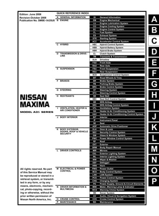
QUICK REFERENCE INDEX
A GENERAL INFORMATION GI General Information
B ENGINE EM Engine Mechanical
LU Engine Lubrication System
CO Engine Cooling System
EC Engine Control System
FL Fuel System
EX Exhaust System
STR Starting System
ACC Accelerator Control System
C HYBRID HBC Hybrid Control System
HBB Hybrid Battery System
HBR Hybrid Brake System
D TRANSMISSION & DRIVE-
LINE
CL Clutch System
TM Transaxle & Transmission
DLN Driveline
FAX Front Axle
RAX Rear Axle
E SUSPENSION FSU Front Suspension
RSU Rear Suspension
SCS Suspension Control System
WT Road Wheels & Tires
F BRAKES BR Brake System
PB Parking Brake System
BRC Brake Control System
G STEERING ST Steering System
STC Steering Control System
H RESTRAINTS SB Seat Belt
SBC Seat Belt Control System
SR SRS Airbag
SRC SRS Airbag Control System
I VENTILATION, HEATER &
AIR CONDITIONER
VTL Ventilation System
HA Heater & Air Conditioning System
HAC Heater & Air Conditioning Control System
J BODY INTERIOR INT Interior
IP Instrument Panel
SE Seat
ADP Automatic Drive Positioner
K BODY EXTERIOR,
DOORS, ROOF & VEHICLE
SECURITY
DLK Door & Lock
SEC Security Control System
GW Glass & Window System
PWC Power Window Control System
RF Roof
EXT Exterior
BRM Body Repair Manual
L DRIVER CONTROLS MIR Mirrors
EXL Exterior Lighting System
INL Interior Lighting System
WW Wiper & Washer
DEF Defogger
HRN Horn
M ELECTRICAL & POWER
CONTROL
PWO Power Outlet
BCS Body Control System
LAN LAN System
PCS Power Control System
CHG Charging System
PG Power Supply, Ground & Circuit Elements
N DRIVER INFORMATION &
MULTIMEDIA
MWI Meter, Warning Lamp & Indicator
WCS Warning Chime System
SN Sonar System
AV Audio, Visual & Navigation System
O CRUISE CONTROL CCS Cruise Control System
P MAINTENANCE MA Maintenance
All rights reserved. No part
of this Service Manual may
be reproduced or stored in a
retrieval system, or transmit-
ted in any form, or by any
means, electronic, mechani-
cal, photo-copying, record-
ing or otherwise, without the
prior written permission of
Nissan North America, Inc.
Edition: June 2008
Revision:October 2008
Publication No. SM9E-1A35U0
2. FOREWORD
This manual contains maintenance and repair procedure for the 2009
NISSAN Maxima.
In order to assure your safety and the efficient functioning of the vehicle,
this manual should be read thoroughly. It is especially important that the
PRECAUTIONS in the GI section be completely understood before starting
any repair task.
All information in this manual is based on the latest product information
at the time of publication. The right is reserved to make changes in specifi-
cations and methods at any time without notice.
IMPORTANT SAFETY NOTICE
The proper performance of service is essential for both the safety of
the technician and the efficient functioning of the vehicle.
The service methods in this Service Manual are described in such a
manner that the service may be performed safely and accurately.
Service varies with the procedures used, the skills of the technician
and the tools and parts available. Accordingly, anyone using service
procedures, tools or parts which are not specifically recommended
by NISSAN must first be completely satisfied that neither personal
safety nor the vehicle’s safety will be jeopardized by the service
method selected.
3. 2009
QUICK REFERENCE CHART: MAXIMA
QUICK REFERENCE CHART: MAXIMA
Engine Tune-up Data INFOID:0000000004455940
GENERAL SPECIFICATIONS
INFOID:0000000004455941
DRIVE BELT
Cylinder arrangement V-6
Displacement cm3
(cu in) 3,498 (213.45)
Bore and stroke mm (in) 95.5 x 81.4 (3.760 x 3.205)
Valve arrangement DOHC
Firing order 1-2-3-4-5-6
Number of piston rings
Compression 2
Oil 1
Number of main bearings 4
Compression ratio 10.3:1
Compression pressure
kPa (kg/cm2
, psi)/300 rpm
Standard 1,275 (13.0, 185)
Minimum 981 (10.0, 142)
Differential limit between cylinders 98 (1.0, 14)
Cylinder number
Valve timing
(Valve timing control - “OFF”)
Unit: degree
a b c d e f
240 240 −10 70 10 50
SEM713A
PBIC0187E
Tension of drive belt Belt tension is not necessary, as it is automatically adjusted by drive belt auto-tensioner.
4. QUICK REFERENCE CHART: MAXIMA
2009
INFOID:0000000004455942
SPARK PLUG
Unit: mm (in)
Front Wheel Alignment (Unladen*) INFOID:0000000004455943
: Fuel, radiator coolant and engine oil full. Spare tire, jack, hand tools and mats in designated positions.
Make DENSO
Standard type FXE22HR11
Gap
Standard 1.1 (0.043)
Limit 1.4 (0.055)
Market USA/Canada Mexico
Tire size 245/45R18 245/40R19 245/45R18 245/40R19
Camber
Degree minute (Decimal de-
gree)
LH
Minimum -1°5’ (-1.10°) -1°10’ (-1.15°) -0°55’ (-0.95°)
Nominal -0°20’ (-0.35°) -0°40’ (-0.65°) -0°10’ (-0.20°)
Maximum 0°25’ (0.40°) 0°20’ (0.35°) 0°35’ (0.55°)
RH
Minimum -1°20’ (-1.35°) -1°25’ (-1.40°) -1°10’ (-1.20°)
Nominal -0°35’ (-0.60°) -0°40’ (-0.65°) -0°25’ (-0.45°)
Maximum 0°10’ (0.15°) 0°05’ (0.10°) 0°20’ (0.30°)
Maximum left and right differ-
ence
-0°15’ ±° 0°33’ (-0.25°± 0.55°)
Caster
Degree minute (Decimal degree)
Against ground surface
Minimum 4°10’ (4.20°) 4°15’ (4.25°) 3°45’ (3.75°)
Nominal 4°55’ (4.95°) 5°00’ (5.00°) 4°30’ (4.50°)
Maximum 5°40’ (5.70°) 5°45’ (5.75°) 5°15’ (5.25°)
Maximum left
and right dif-
ference
0°33’ (0.55°)
Kingpin offset
Degree minute (Decimal degree)
Minimum 13°40’ (13.65°) 13°20’ (13.35°)
Nominal 14°25’ (14.40°) 14°05’ (14.10°)
Maximum 15°10’ (15.15°) 14°50’ (14.85°)
Total toe-in
Distance (A -
B)
Minimum 0 mm
Nominal 1 mm
Maximum 2 mm
SFA234AC
6. QUICK REFERENCE CHART: MAXIMA
2009
*2: Without top load sunroof
*3: With top load sunroof
Brake Specifications INFOID:0000000004455946
Unit: mm (in)
Front Disc Brake INFOID:0000000004455947
Unit: mm (in)
Rear Disc Brake INFOID:0000000004455948
Unit: mm (in)
Brake model Kiriu
Wheel size 457 (18) 483 (19)
Front brake
Cylinder bore diameter 57.15 (2.250)
Pad length × width × thickness 123.6 × 47.5 × 11 (4.866 × 1.870 × 0.433)
Rotor outer diameter × thickness 320 × 28 (12.598 × 1.102) TBD
Rear brake
Brake model Kiriu
Cylinder bore diameter 34.93 (1.375)
Pad length × width × thickness 83.0 × 33.0 × 8.5 (3.268 × 1.299 × 0.335)
Rotor outer diameter × thickness 308 × 16 (12.126 × 0.630)
Master cylinder Cylinder bore diameter 23.81 (0.937)
Control valve Valve model Electric brake force distribution
Brake booster Booster model Bosch
Recommended brake fluid DOT 3
Brake model Kiriu
Wheel size 457 (18) 483 (19)
Brake pad
Standard thickness (new) 11.0 (0.433)
Repair limit thickness 2.0 (0.079)
Disc rotor
Standard thickness (new) 28.0 (1.102)
Repair limit thickness 26.0 (1.024)
Thickness variation (measured at 8 positions) 0.015 (0.0006)
Maximum runout (with it attached to the vehicle) 0.035 (0.0014)
Brake model Kiriu
Wheel size 457 (18) 483 (19)
Brake pad
Standard thickness (new) 8.5 (0.335)
Repair limit thickness 1.0 (0.039)
Disc rotor
Standard thickness (new) 16.0 (0.630)
Repair limit thickness 14.0 (0.551)
Thickness variation (measured at 8 positions) 0.015 (0.0006)
Maximum runout (with it attached to the vehicle) 0.05 (0.002)
7. 2009
QUICK REFERENCE CHART: MAXIMA
Brake Pedal INFOID:0000000004455949
Unit: mm (in)
Fluids and Lubricants - US and Canada INFOID:0000000004455950
Brake pedal free height (H) 190.7 - 202.7 (7.51 - 7.98)
Brake pedal full stroke (S) 130.0 (5.12)
Clearance between brake pedal bracket and threaded end of stop lamp switch and ASCD
cancel switch (C1) or (C2)
0.74 - 1.96 (0.0291 - 0.0772)
AWFIA0433ZZ
Description
Capacity (Approximate)
Recommended Fluids/Lubricants
US measure Imp measure Liter
Fuel 20 gal 16-5/8 gal 75.6
Unleaded gasoline with an octane rating
of at least 91 AKI (RON 96)
Engine oil
Drain and refill
With oil filter
change
4-7/8 qt 4 qt 4.6
• Engine oil with API Certification Mark
*1*2
• Viscosity SAE 5W-30 *2
Without oil fil-
ter change
4-1/2 qt 3-3/4 qt 4.3
Dry engine (Overhaul) 5-1/4 qt 4-3/8 qt 5.0
Cooling system
with reservoir tank
2-1/8 gal 1-3/4 gal 8.2
Genuine NISSAN Long Life Antifreeze/
Coolant or equivalent
CVT fluid 10-3/4 qt 9 qt 10.2
Genuine NISSAN CVT Fluid NS-2 *3
Power steering fluid (PSF) 1-1/8 qt 7/8 qt 1.0 Genuine NISSAN PSF or equivalent*4
Brake fluid — — —
Genuine NISSAN Super Heavy Duty
Brake Fluid*4 or equivalent
DOT 3 (US FMVSS No. 116)
Brake grease — — — PBC (poly butyl cuprysil)
Brake pad plate grease — — — Molykote AS880N grease or equivalent
Multi-purpose grease — — — NLGI No. 2 (Lithium soap base)
Air conditioning system refrigerant 1.21 ± 0.055 lb — 0.55 ± 0.025 kg HFC-134a (R-134a) *5
8. QUICK REFERENCE CHART: MAXIMA
2009
*1: For further details, see “Engine Oil Recommendation”.
*2: NISSAN recommends Genuine NISSAN Ester Engine Oil available at your NISSAN dealer.
*3: Using automatic transmission fluid other than Genuine NISSAN CVT Fluid NS-2 will damage the CVT, which is not covered
by the NISSAN new vehicle limited warranty.
*4: DEXRONTM VI type ATF or Canada NISSAN Automatic Transmission Fluid may also be used.
*5: For further details, see "Air conditioning specification label".
Fluids and Lubricants - Mexico INFOID:0000000004455951
*1: For further details, see “SAE Viscosity Number”.
*2: Use Genuine NISSAN Engine Coolant or equivalent in its quality, in order to avoid possible aluminum corrosion within the engine
cooling system caused by the use of non-genuine engine coolant.
Note that any repairs for the incidents within the engine cooling system while using non-genuine engine coolant may not be
covered by the warranty even if such incidents occurred during the warranty period.
*3:Using transmission fluid other than Genuine NISSAN CVT fluid NS-2 will damage the CVT, which is not covered by the war-
ranty.
*4: DEXTRON™ VI type ATF may also be used.
Air conditioning system oil 5.03 fl oz 5.3 fl oz 150 m
NISSAN A/C System Oil Type S or
equivalent *5
Windshield washer fluid — — —
Genuine NISSAN Windshield Washer
Concentrate Cleaner & Antifreeze or
equivalent
Description
Capacity (Approximate)
Recommended Fluids/Lubricants
US measure Imp measure Liter
Capacity (Approxi-
mate) Recommended Fluids/Lubricants
Liter Imp measure
Engine oil
Drain and refill
With oil filter change 4.6 4 qt Genuine NISSAN engine oil*1
API grade SL or SM*1
ILSAC grade GF-2, GF-3 or GF-4*1
Viscosity SAE 10W-30
Without oil filter change 4.3 3-3/4 qt
Dry engine (engine overhaul) 5.4 4-3/4 qt
Cooling system (with reservoir) 8.2 1-3/4 gal
Genuine NISSAN Engine Coolant or
equivalent in its quality*2
CVT fluid 10.2 9 qt Genuine NISSAN CVT fluid NS-2*3
Brake fluid — — DOT 3 (US FMVSS No. 116)
Power steering fluid 1.0 7/8 qt Genuine NISSAN PSF or equivalent *4
Multi-purpose grease — — NLGI No. 2 (Lithium soap base)
9. GI-1
GENERAL INFORMATION
C
D
E
F
G
H
I
J
K
L
M
B
GI
SECTION GI
N
O
P
CONTENTS
GENERAL INFORMATION
HOW TO USE THIS MANUAL ..................
.... 3
HOW TO USE THIS MANUAL .......................
..... 3
Description ..........................................................
......3
Terms ..................................................................
......3
Units ....................................................................
......3
Contents ..............................................................
......3
Relation between Illustrations and Descriptions .
......4
Components ........................................................
......4
HOW TO FOLLOW TROUBLE DIAGNOSES..... 6
Description ..........................................................
......6
How to Follow Test Groups in Trouble Diagnosis......6
Key to Symbols Signifying Measurements or Pro-
cedures ...............................................................
......7
HOW TO READ WIRING DIAGRAMS ...........
..... 9
Connector symbols .............................................
......9
Sample/wiring diagram -example- .......................
....10
Description ..........................................................
....11
ABBREVIATIONS ..........................................
....13
Abbreviation List ..................................................
....13
TIGHTENING TORQUE OF STANDARD
BOLTS ............................................................
....14
Tightening Torque Table .....................................
....14
RECOMMENDED CHEMICAL PRODUCTS
AND SEALANTS ............................................
....15
Recommended Chemical Products and Sealants
....15
TERMINOLOGY .............................................
....16
SAE J1930 Terminology List ...............................
....16
FEATURES OF NEW MODEL ..................
...20
IDENTIFICATION INFORMATION .................
....20
Model Variation ...................................................
....20
Identification Number ..........................................
....21
Identification Plate ...............................................
....22
Engine Serial Number .........................................
....22
CVT Number ........................................................
....22
Dimensions ..........................................................
....23
Wheels & Tires ....................................................
....23
PRECAUTION ...........................................
...24
PRECAUTIONS .................................................24
Description ...........................................................
....24
Supplemental Restraint System (SRS) "AIR BAG"
and "SEAT BELT PRE-TENSIONER" .................
....24
Precautions Necessary for Steering Wheel Rota-
tion after Battery Disconnect ...............................
....24
Procedures without Cowl Top Cover ...................
....25
General Precautions ............................................
....25
Three Way Catalyst .............................................
....26
Fuel (Unleaded Premium Gasoline Required)
VQ35DE ..............................................................
....27
Multiport Fuel Injection System or Engine Control
System .................................................................
....27
Hoses ..................................................................
....27
Engine Oils ..........................................................
....28
Air Conditioning ...................................................
....29
LIFTING POINT .................................................30
Special Service Tool ............................................
....30
Garage Jack and Safety Stand ............................
....30
2-Pole Lift ............................................................
....31
Board-on Lift ........................................................
....32
TOW TRUCK TOWING .....................................33
Tow Truck Towing ...............................................
....33
Vehicle Recovery (Freeing a Stuck Vehicle) .......
....33
BASIC INSPECTION ................................
...35
SERVICE INFORMATION FOR ELECTRICAL
INCIDENT ..........................................................35
Work Flow ............................................................
....35
Control Units and Electrical Parts ........................
....35
How to Check Terminal .......................................
....36
Intermittent Incident .............................................
....39
Circuit Inspection .................................................
....42
10. Thank you very much for
your reading. Please Click
Here. Then Get COMPLETE
MANUAL. NO WAITING
NOTE:
If there is no response to
click on the link above,
please download the PDF
document first and then
click on it.
11. GI-2
CONSULT-III CHECKING SYSTEM ...............
... 47
Description ...........................................................
... 47
Function and System Application ........................
... 47
CONSULT-III Data Link Connector (DLC) Circuit ... 48
Wiring Diagram ....................................................
... 49
12. HOW TO USE THIS MANUAL
GI-3
< HOW TO USE THIS MANUAL >
C
D
E
F
G
H
I
J
K
L
M
B
GI
N
O
P
HOW TO USE THIS MANUAL
HOW TO USE THIS MANUAL
Description INFOID:0000000003891696
This volume explains “Removal, Disassembly, Installation, Inspection and Adjustment” and “Trouble Diag-
noses”.
Terms INFOID:0000000003891697
• The captions WARNING and CAUTION warn you of steps that must be followed to prevent personal injury
and/or damage to some part of the vehicle.
WARNING indicates the possibility of personal injury if instructions are not followed.
CAUTION indicates the possibility of component damage if instructions are not followed.
BOLD TYPED STATEMENTS except WARNING and CAUTION give you helpful information.
Standard value: Tolerance at inspection and adjustment.
Limit value: The maximum or minimum limit value that should not be exceeded at inspection and adjust-
ment.
Units INFOID:0000000003891698
• The UNITS given in this manual are primarily expressed as the SI UNIT (International System of Unit), and
alternatively expressed in the metric system and in the yard/pound system.
Also with regard to tightening torque of bolts and nuts, there are descriptions both about range and about the
standard tightening torque.
“Example”
Range
Standard
Contents INFOID:0000000003891699
• A QUICK REFERENCE INDEX, a black tab (e.g. ) is provided on the first page. You can quickly find the
first page of each section by matching it to the section's black tab.
• THE CONTENTS are listed on the first page of each section.
• THE TITLE is indicated on the upper portion of each page and shows the part or system.
• THE PAGE NUMBER of each section consists of two or three letters which designate the particular section
and a number (e.g. “BR-5”).
• THE SMALL ILLUSTRATIONS show the important steps such as inspection, use of special tools, knacks of
work and hidden or tricky steps which are not shown in the previous large illustrations.
Assembly, inspection and adjustment procedures for the complicated units such as the automatic transaxle
or transmission, etc. are presented in a step-by-step format where necessary.
Outer Socket Lock Nut : 59 - 78 N·m (6.0 - 8.0 kg-m, 43 - 58 ft-lb)
Drive Shaft Installation Bolt : 44.3 N·m (4.5 kg-m, 33 ft-lb)
13. GI-4
< HOW TO USE THIS MANUAL >
HOW TO USE THIS MANUAL
Relation between Illustrations and Descriptions INFOID:0000000003891700
The following sample explains the relationship between the part description in an illustration, the part name in
the text and the service procedures.
Components INFOID:0000000003891701
• THE LARGE ILLUSTRATIONS are exploded views (see the following) and contain tightening torques, lubri-
cation points, section number of the PARTS CATALOG (e.g. SEC. 440) and other information necessary to
perform repairs.
The illustrations should be used in reference to service matters only. When ordering parts, refer to the appro-
priate PARTS CATALOG.
Components shown in an illustration may be identified by a circled number. When this style of illustration is
used, the text description of the components will follow the illustration.
SAIA0519E