NETRA on SIGGRAPH 2010
•Télécharger en tant que PPTX, PDF•
3 j'aime•23,568 vues

Our Presentation at ACM SIGGRAPH 2010.

Recommandé
Recommandé
Contenu connexe
Tendances
Tendances (20)
En vedette
En vedette (20)
Similaire à NETRA on SIGGRAPH 2010
Similaire à NETRA on SIGGRAPH 2010 (20)
Plus de Vitor Pamplona
Plus de Vitor Pamplona (19)
Dernier
Dernier (20)
NETRA on SIGGRAPH 2010
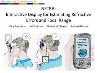
- 1. NETRA: Interactive Display for Estimating Refractive Errors and Focal Range Vitor Pamplona Ankit Mohan Manuel M. Oliveira RameshRaskar 1
- 2. 2 NETRA: Near Eye Tool for Refractive Assessment Vitor Pamplona Ankit Mohan Manuel M. Oliveira RameshRaskar
- 3. Challenge 2B have refractive errors 0.6B have URE 4.5B have a cell phone 6.5 Billion people NETRA at LVP Eye Institute 3
- 4. 4 Computational Photography Optometry/Opthalmalogy Measure .. Overcome Limitations .. Extend Abilities
- 5. Accuracy Sharpness Estimation is subjective Brightness affects results Pupil size variation and DoF Cost Trial Lens Set > $150 Bulky Snellen chart Phoropter Trial lenses Reading Charts
- 6. Needs expert, Moving parts, Shining lasers * Phoropter-based: $5,000.00
- 7. Shack-Hartmann Wavefront Sensor Wavefrontaberrometer Expensive; Bulky, Requires trained professionals 7
- 8. Shack-Hartmann Wavefront Sensor Laser Sensor 8 Shack & Platt 1971 Liang et al 1994 David Williams et al, Rochester Spot Diagram Planar Wavefront Microlens Array Shack-Hartmann ~ Lightfields Levoy et al 2009 Zhang and Levoy 2009: Observable Light Field Oh, Raskar, Barbastathis 2009: Augmented Light Field
- 9. Shack-Hartmann Wavefront Sensor Laser Spot Diagram 9 Sensor Displacement = Local Slope of the Wavefront
- 10. NETRA= Inverse of Shack-Hartmann 10 Spot Diagram on LCD Cell Phone Display Eye Piece
- 11. 11 Inverse of Shack-Hartmann User interactively creates the Spot Diagram Spot Diagram on LCD Displace 25 points but 3 parameters
- 12. Optometry Infinity Subject can focus at infinity Human Eye Accommodation Range Normal Vision 10cm Infinity 12
- 13. Myopia (nearsightedness) Infinity Subject cannot focus at far distances Accommodation Range Normal Vision Shifted Accommodation Range Myopia 10cm Infinity 13
- 14. Myopia Correction Infinity Subject can focus at infinity Human Eye Accommodation Range Normal Vision Shifted Accommodation Range Myopia 10cm Infinity 14
- 15. Myopia Correction Infinity Subject can focus at infinity Divergent Lens Human Eye Accommodation Range Normal Vision Corrected Myopia Myopia 10cm Infinity 15
- 16. Hyperopia (farsightedness) Infinity Wrong focal point Human Eye Accommodation Range Normal Vision Myopia Hyperopia 10cm Infinity 16
- 17. Hyperopia (farsightedness) ‘Beyond’ Infinity Human Eye Accommodation Range Normal Vision Myopia Hyperopia 10cm Infinity 17
- 18. Hyperopia Correction Infinity Convergent Lens Human Eye Accommodation Range Normal Vision Myopia Hyperopia 10cm Infinity 18 Corrected Hyperopia
- 19. Refractive Errors and Shifted Range Perfect vision Need to measure Myopia Hyperopia 10cm Infinity 19 1m 33cm Distance
- 20. Refractive Errors and Shifted Range Perfect vision Myopia Hyperopia 10cm Infinity 20 1m 33cm Distance 10D 0D 3D 1D -1D -3D Diopter Diopter = 1/Distance
- 21. Relaxed Eye with Myopia Eye Red pointat infinity Blurred point Focusing Range perfect vision myopia hyperopia ~10cm infinity 21
- 22. Relaxed Eye with Myopia Eye Pinholes Distinct image points Red pointat infinity Focusing Range perfect vision Scheiner’s Principle myopia hyperopia ~10cm infinity 22
- 23. Relaxed Eye with Myopia Eye Display A Distinct image points Virtual red pointat infinity B Focusing Range perfect vision myopia hyperopia ~10cm infinity 23
- 24. Relaxed Eye with Myopia Eye Display Move spots towardseach other A Distinct image points Virtual red pointat finite distance B Focusing Range perfect vision myopia hyperopia ~10cm infinity 24
- 25. Relaxed Eye with Myopia Eye Display Move spots towardseach other A Points overlap Virtual red pointat finite distance B Focusing Range perfect vision myopia hyperopia ~10cm infinity 25
- 26. Relaxed Eye with Myopia Eye Display Move spots towardseach other A Points overlap Virtual red pointat finite distance B Focusing Range perfect vision myopia hyperopia ~10cm infinity 26
- 27. Relaxed Eye with Myopia Eye Points overlap Point at infinity Focusing Range perfect vision myopia hyperopia ~10cm infinity 27
- 28. Relaxed Perfect Eye Display A Points overlap Virtual red pointat infinity B Focusing Range perfect vision myopia hyperopia ~10cm infinity 28
- 29. Relaxed Eye with Hyperopia 29 Eye Display A Distinct image points Virtual red pointat infinity B Focusing Range perfect vision myopia hyperopia ~10cm infinity
- 30. Relaxed Eye with Hyperopia Move spots awayfrom each other Display Display A Points overlap B Virtual point“beyond” infinity Focusing Range perfect vision myopia hyperopia ~10cm infinity 30
- 31. Relaxed Eye with Hyperopia Move spots awayfrom each other Points overlap Virtual point“beyond” infinity Focusing Range perfect vision myopia hyperopia ~10cm infinity 31
- 32. NETRA: Using pinholes 32 Pinhole array Patterns on an LCD
- 33. NETRA: Using Lens to Increase Light Microlensarray Patterns on an LCD a f 33 t Pixel Pitch Virtual Depth
- 34. Interactive Method Farthest Focal Point (myopia, hyperopia) 34
- 35. Interactive Method 35 Farthest Focal Point (myopia, hyperopia)
- 36. Interactive Method Farthest Focal Point (myopia, hyperopia) 36
- 38. Hi-res displays + interaction
- 40. No moving parts, lasers
- 41. Blur -> Alignment problem
- 42. ~ Lightfield Display for Single Eye
- 43. Astigmatism
- 44. Novel Patterns
- 45. Focal Range
- 47. Astigmatism: angle-dependent refractive error http://www.elizabethpope.co.uk/eyeinfo/astigmatism.html 39
- 48. Astigmatism: angle-dependent refractive error http://www.elizabethpope.co.uk/eyeinfo/astigmatism.html 40
- 49. Refractive Power as a Function of Angle 41 Axis Cyl. Cylinder Unknowns: Sphere
- 50. Astigmatism Cross or points may never meet with a 1d search ! 42
- 51. Astigmatism Lines reduce the problem to a 1d search 43
- 52. Interactive Method Farthest Focal Point (myopia, hyperopia, astigmatism) 44
- 53. Interactive Method Farthest Focal Point (myopia, hyperopia, astigmatism) 45
- 54. Interactive Method Farthest Focal Point (myopia, hyperopia, astigmatism) 46
- 55. Interactive Method Farthest Focal Point (myopia, hyperopia, astigmatism) 47
- 56. Interactive Method Farthest Focal Point (myopia, hyperopia, astigmatism) 48
- 57. Evaluation Prototype Camera simulates the perfect eye Trial lenses simulate lens aberration Minification LCD Display 49
- 58. Subjective Validation: User Study 50
- 59. Measuring the Accommodation Range 51 Myopia Perfect vision Hyperopia ~10cm Infinity Step 2: Near limit Step 1: Far limit
- 60. Measuring the Accommodation Range 52 Myopia Perfect vision Hyperopia ~10cm Infinity Step 2: Near limit Step 1: Far limit
- 61. Measuring the Accommodation Range 53 Myopia Perfect vision Hyperopia ~10cm Infinity Step 2: Near limit Step 1: Far limit
- 62. Relaxed Eye Display A Points overlap Virtual Point at the far limit B 54
- 63. Accommodated Eye Display Move points towards each other A Points overlap B 55 Virtual pointgetting closer Subject Accommodates to fix the “blur”
- 64. Accommodated Eye Display Move points towards each other A Points overlap B 56 Virtual pointgetting closer Subject Accommodates to fix the “blur”
- 65. Accommodated Eye Display Move points towards each other A Points overlap B 57 Virtual pointgetting closer Subject cannot accommodate more than the previous point
- 66. Patterns for Alignment Task 58 A B A B A B A B A B Displayed Subject view A B A B A B A B A B Displayed Subject view Visual Cryptography [NaorShamir94]
- 67. Patterns for Alignment Task 59 A B A B A B A B A B Displayed Subject view A B A B A B A B A B Displayed Subject view Visual Cryptography [NaorShamir94]
- 68. Subject View as Convolution Display Subject’ s View Subject’ s View
- 69. Subject View Viewmaster prototype 61 +3D to -5D with accommodation Scaled Patterns G(0D) G(+5D) G(-5D) h - Jittered Pinholes
- 70. Summary of Interaction Accommodation Range Farthest Point (myopia, hyperopia, astigmatism) NearestPoint (presbyopia) 62
- 71. Limitations Children Ability to align lines Single Eye test Other eye for convergence-forced accommodation Resolution is a function of the display DPI Samsung Behold II – 160 DPI – 0.35D Google Nexus One – 250 DPI – 0.2D Apple iPhone 4G – 326 DPI – 0.14D 63
- 72. Future Work Clinical research for an optometry device Side-by-side validation tests Field trials Tests for cataract, lazy eye, etc Opportunity to monitor one’s eyesight Diabetes/Glucose non-invasive meter Unstable lens prescriptions Distribution in Developing Countries Software app for free Eyepiece blueprint to NGOs for <$1 More at EyeNetra.com 64
- 73. Future Work Multi-focus display without moving parts [Akeley04][Rolland00][Hua09] [Barsky04] Personalized devices (clear without glasses) Alarm Clock Cell phones eReaders 65 Inju Fernando Meyer
- 74. Acknowledgements Volunteers Dr. Joseph Ciolino (MGH Mass Eye and Ear Inst.) Dr. Fuentanta Vera Diaz (Schepens Eye Research Inst.) Dr. James Kobler (MGH Mass Eye and Ear Inst.) Dr. ShrikantBhardwaj, (LV Prasad Eye Institute, India) Sponsors CNPq-Brazil Alfred P. Sloan Research Fellowship Google Samsung 66
- 75. NETRA: Display for Eye Refraction Tests Inverse of Shack-Hartmann wavefrontaberrometer High-resolution displays and user interaction Focal Parameters Myopia, Hyperopia, Astigmatism Focal range Thermometer for the eye Measurement not prescription Promote Self Awareness Impact in Developing Countries 600 Million without corrective glasses $1 cost, easy to deploy 67
- 76. NETRA: Interactive Display for Estimating Refractive Errors and Focal Range Vitor Pamplona Ankit Mohan Manuel M. Oliveira RameshRaskar 68
Notes de l'éditeur
- In this paper, we show a self-optometry solution. You look at a cell phone display thru a clip-on eye piece, interactively align a few patterns, hit calculate and get data for your eye prescription.
- We call our tool NETRA: near eye tool for refractive assessmentsuch as nearsightedness/far/astigmatismBasic idea is to create a unique interactive lightfield display near the eye and is possible due to the highresolution of modern LCDs.
- 2 billion people have refractive errorsAnd half a billion in developing countries worldwide have uncorrected vision that affects their daily livelyhood. They don’t have access to an optometrist or it simply too expensive. While making and distributing of lenses has become quite easy now, surprisingly there is still no easy solution for measuring eyesight.Can we use a fraction of the 4.5B cellphone displays to address this problem?
- In Computational photography, we try to understand howcameras work, overcome their limitations and extend the abilities of these cameras. But we all carry atleast 3 cameras with us. Yes, your cellphone camera and the two eyes. Can we transition ideas from computational photography that deal with focus blur, motion blur and so on into optometry and opthalmalogy?
- Reading charts appear to be an easy solution, this method has too many problems. Sharpness of legible text is very subjective. The brightness of the chart has to be very carefully chosen otherwise the pupil size will change, increasing depth of field, and allowing user to recognize even lower rows.The trial lenses + the lens frame the doctor will use also cost over $150% Reading chart tests involve using a frame or a phoropter. The doctor will swing a sequence of lenses in front of your eye and ask for which lens allows you to see the lower rows on the reading chart.
- For better precision, there are many kinds of solutions, some really clever. The beauty of netra is that it avoids moving parts or shining lasers, and all intelligence is in the software.
- The most accurate method is based on a so called SH WS. It involves shining a laser at the back of the retina and observing the wavefront using a sophisticated sensor.We ask user to generate a spot diagram. But navigating in a high dimensional space ischallenging so we come up with a strikingly simple approach to let the user interactively create the spotdiagram.We are first to make connection between Shack Hartmann and Lightfields (and it goes well with recentwork in computational photography about ALF and Zhang/Levoy). Connection to Adaptive optics/Astronomy. The way that this device works is that, it shines a lasers in the eye, the laser is reflected in the retina and comes out of the eye being distorted by the cornea. These light rays reaches an array of lenses that focus them to dots in a sensor. The device measures how much this dots deviate from the ideal case. Since it uses lasers, the device is expensive and requires trained professionals
- For a normal eye, the light coming out of the eye forms a parallel wavefront. The sensor has a lenslet array and we get a spot diagram of uniform dots.This lenslet should remind you of a lightfield camera, and in fact Levoy and others showed last year that there is a close relationship between the two.In addition, Zhang and Levoy, plus our grp has shown the relationship between wavefront sensing and lightfield sensing.
- When the eye has a distortion, the spot diagram is not uniform.And the displacement of the spots from the center indicates the local slope of the wavefront. From the slope one can integrate and recover the wave shape.
- NETRA uses an exact inverse of this sensor. We get rid of the laser and we instead show the same spot diagram in a cellphone display. For normal eye, it will appear as a dot to the user.And then we replace the sensor for a light field display. If the user sees a single red dot, he does not need glasses, but if he sees more than one, he interacts with this display.
- For eye with distortion, the user will interactively displace the 25 points so that he will see a single spot. Of course changing 25 spot locations is cumbersome, but we realize that there are only 3 parameters for eye-prescription and we help the user navigate thru this space efficiently.But if you think about these theory, you will realize that we have the dual of the shack-hartmann. First we though out the laser.
- Before we go on. Here is a 2 minute primer on optometry.So, in a perfect vision system, the light coming from a point at infinity will converge to a single point at the retina. A subject with perfect vision see clearly from infinity to up to 10cm.
- Myopes cannot see far. Therefore, all the rays coming from a point at infinity, converges before the retina. The Accommodation range for those people is shifted to close, so they can closer than regular individuals.
- The correction for myopia includes a divergent lens, which brings the focal point back to the retina by shifting the Accommodation range.
- Hyperopes cannot see close. All the rays coming from a point at infinity, converges behind the retina.
- The Accommodation range for those people is shifted to the far field, so they can actually see ‘infinity and beyond’, much like the buzz lightyear.
- The correction for myopia includes a convergent lens, which shifts the Accommodation range back to the regular indivudial.
- We need to measure the difference between the subject’s farthest focal point wrt infinity.
- And this is measured in diopters which is 1 divided by this distance.
- So, lets start with an eye with myopia. Remember, they cannot see far, so a red point at infinity for them will look like a red blur.
- Using Shceiner’s principle, if we put two pinholes in the field, this will instead create two distinct dots.
- Instead of a distant point source, we put an LCD display behind the pinholes. If we draw two spots exactly under these pin-holes, we create a virtual point at infinity.
- So, as we move the two red circles toward each other, the virtual point gets closer to the subject and he sees the two red dots getting closer.
- When this two red circles overlaps for the subject, we can compute d based on the spot displacements
- Which is the distance between the eye and this virtual point.
- Turns out that the inverse of D is the refractive power required for this person to see clearly objects at infinity. In other words, the lens that will shift the accommodation range of this subject back to the regular one.
- In case of a perfect eye using the system, since the subject can see far, he will see the two points overlapping in his retina, meaning that he does not need glasses.
- Hyperopes focal point is behind the retina.
- When they move these spots away from each other, we are moving the virtual point beyond infinityAnd buzz lightyear will entually see they overlap, and when this happens, we can compute the…
- convergent lens required to shift their accommodation range to the normal stage.
- The version that I showed to you uses pinholes to encode the apperture.
- However, if we change these pinholes for lenses, we can increase the light and also the number of testing points in the corneal surface, meaning that we can actually create a map of one’s refractive error. As you can see the pixel pitch directly affects the precision of creating virtual depth as well as refraction estimation.
- And number of clicks required for alignment indicates the refractive error
- In practice we display lines on the screen and the subject overlaps these lines by pressing the buttons of the cell phone or in the computer.
- Two main benefitsNo moving partsBlur into a more objective alignment problemUnfortunately, the lightfield and virtual point analogy does not extend to astigmatism and we can also compute ‘focal range’ rather than just relaxed state. Vitor will cover this.”ThanksRamesh, There is a third condition called astigmatism
- which is anangle-dependent refractive error. An astigmatic subject has two main focal lengths in perpendicular meridians. One …
- Stronger and one weaker
- Think of a cornea with the shape of an american football creating a cylindrical aberration with unknown focal length and axis.
- The required correction is now a function of measured angle. In order to measure the farthest point for these guys, we need to evaluate Cylindrical component, the Spherical component, and the angle theta on the equation. However, the interpolation of refractive powers between C and S leads to a situation where the pattern drawn on the screen matters.
- As you can see in this video, the astigmatic lenses create a deviation on the path of the pattern, and they may never overlap, turning the alignment task into a 2D search for some angles.
- However, if we drawn lines perpendicular to the measured angle, the alignment task is again an 1D search. The deviation still exists, but the pattern makes the task easier.
- So, we do the alignment task for a few meridians
- By showing oriented lines on the display.
- In the end, we best fit the sinusoidal curve over the four measured values to estimate the astigmatic parameters.
- In the end, we best fit the sinusoidal curve over the four measured values to estimate the astigmatic parameters.
- Using a minification system, we performed user study with a high resolution display. Using a a camera to simulate perfect eye and a trial set of lenses to simulate lens aberration, the average spherical error was under 0.09 diopter and astigmatism axis error of 8 degrees.
- In subjective human studies, the difference from known prescription was under 0.5 diopters. But note that the current prescription may not match the actual refractive error.
- Ours is the only system where one can estimate not only the farthest point
- one can focus but also
- the nearest point without any mechanically moving parts. So, in order to measure the closest reading point
- We draw a pattern on the screen that induces accommodation. In this way, when we move A and B closer on the screen,
- the user will try to focus on a closer object. We can move this virtual point all the way to the nearest discernable point.
- When the user is not able to focus anymore, the visual system give up and the user start seeing more than one pattern.
- As I sad before, this is possible because we can draw whatever we want in the display. We tested many patterns, static and dynamic, including visual cryptography.
- Turns out that the best pattern to induce accommodation is the sinosoidal curves aligned perpendicular to the measurement angle.
- We have complete freedom for pattern G on display and the filter pattern h, which has been pin hole grid so far. But observe that subjects view is just a convolution of the pattern g and the filter h. So here is a very interesting effect. If we show this convoluted pattern with same filter, we get double convolution. If h is a broadband random dot pattern, the double convolution is a delta function, which means user will again see the pattern g.
- We exploited this trick to build a viewmaster system. In this case, instead of moving lines closer we scale the pattern. The amount of scale give us the refractive power needed.
- As a summary, our method has two steps. First measures the farthest point in focus in many angles using lines and the second step measures the nearest point using sinusoidals oriented on the angle of astigmatism.
- Since we are relying on the user interaction, the subject has to be aware of the alignment tasks. So, very young Children may not be able to run the test. Instead of just one eye, one may use both eyes to exploit convergence. And of course, the resolution of NETRA itself is a function of the resolution of the display. With a 326 dpi display, resolution is 0.14 diopters and presciption glasses come in increments of 0.25 diopters. So our system is already sufficiently accurate.
- For future work, we are partnering with many institutions that would like to use our device as an optometry tool and as a new tool for doing research. For instance, we think we have a new opportunity to monitor people eyesight over time.Field trials in regions with cultural and language barriers
- Our work also create a new solution for a multi-focus displays without mechanically moving parts or large depths. Maybe we can even create alrm clock with optical correction built in. So you can read the clock without fiddling for eyeglasses.
- Before I conclude, We would like to thank our collaborators and sponsors.(count to 5)
- As a summary, we introduce the inverse of the Shack Hartmann system using a light field display and user interaction. We convert the blur problem into more objective alignment problem to estimate focal parameters. Our idea can be thought as thermometer for the eye. It is not a replacement for optometrist NETRA provides measurement, not prescriptions. At under $2, we have the cheapest accurateeye test ever. Given the 4.5 billion portable phones out there, we think it is an ideal solution in developing countries.
- So, thanks everyone.
- In this paper, we introduce the dual of the Shack Hartmann system using a light field display and user interaction. We also introduce an interactive technique to create objects at desired depths and an interface to measure refractive parameters of the eye. We validated this two main contributions by measuring lenses and comparing with lens prescriptions.
- Not just user interaction , but far greater impact on people’s lives!
- Image and Range
- Include Myopia Range
- Include Myopia Range
- Show without accommodation and accomodate
- Show without accommodation and accomodate
- Show without accommodation and accomodate
- ??
- ??
- Image and Range
- Include Myopia Range
- Include Myopia Range
- Show without accommodation and accomodate
- Show without accommodation and accomodate
- Show without accommodation and accomodate
- Show without accommodation and accomodate
- … Which is anangle-dependent refractive erros. An astigmatic subject has two focal lengths in perpendicular meridians. One …
- Stronger and one weaker
- In this case, the red meridian is called Spherical, the Blue one is called cylindrical and the axis of the Red meridian indicates the angle of astigmatism. In order to measure the farthest point for these guys, we
- In practice we display lines on the screen and the subject overlaps these lines by pressing the buttons of the cell phone or in the computer.
- When the lines were overlapped, we compute the correction for myopia or hyperopia. However, there is a third disease called astigmatism.
- The average error was under 0.5 diopters for both axis of astigmatism and the axis had an average error of 6 degrees.
- For this case, the average error was 0.09 diopters for myopia and hyperopia and 0.23 for astigmatism. The axis of astigmatism had an error of 8.43 degress
- We validate this extension by measuring the closest sharp point in cameras, and comparing with physical measurements.
- The second round of validation included 6 humans. Both cases we could get pretty close to the actual closest sharp point.
- In order to evaluate this technique, an LCD display was putted 2 meters away of a minification system, which created images in 3320 DPI. Inside the minification system we had a lens array. A camera was used to simulate the perfect eye.
- There is a third condition called astigmatism which means an additional cylindrical aberration with unknown focal length and axis. The required correction now is dependent on angle and this leads to a situation where the pattern drawn on the screen matters.
- There is a third condition called astigmatism which means an additional cylindrical aberration with unknown focal length and axis. The required correction now is dependent on angle and this leads to a situation where the pattern drawn on the screen matters.
- There is a third condition called astigmatism which means an additional cylindrical aberration with unknown focal length and axis. The required correction now is dependent on angle and this leads to a situation where the pattern drawn on the screen matters.