1. Packet Flow through Cisco ASA Firewall
Document ID: 113396
Contents
Introduction
Prerequisites
Requirements
Components Used
Conventions
Background Information
Cisco ASA Packet Process Algorithm
Explanation on NAT
Show Commands
Syslog Messages
Related Information
Introduction
This document describes the packet flow through a Cisco ASA firewall. It shows how the internal packet
processing procedure of the Cisco ASA works. It also discusses the different possibilities where the packet
could be dropped and different situations where the packet progresses ahead.
Prerequisites
Requirements
Cisco recommends that you have knowledge of these topics:
• Cisco ASA 5500 Series Adaptive Security Appliances
Components Used
The information in this document is based on these software and hardware versions:
• Cisco ASA 5500 series Adaptive Security Appliances running software version 8.0 and later
Conventions
Refer to Cisco Technical Tips Conventions for more information on document conventions.
Background Information
The interface that receives the packet is called the ingress interface and the interface through which the packet
exits is called the egress interface. When referring to the packet flow through any device, it can be easily
simplified by looking at the task in terms of these two interfaces.
Here is a sample scenario:
2. When an inside user (192.168.10.5) attempts to access a web server in the DMZ network (172.16.10.5), the
packet flow looks like this:
• Source address − 192.168.10.5
• Source port − 22966
• Destination address − 172.16.10.5
• Destination port − 8080
• Ingress interface − Inside
• Egress interface − DMZ
• Protocol used − TCP
By determining the details of the packet flow as described here, it is easy to isolate the issue to this specific
connection entry.
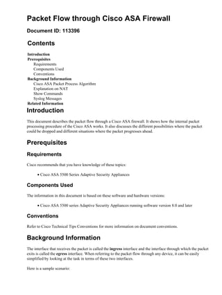
Cisco ASA Packet Process Algorithm
Here is a diagram of how the Cisco ASA processes the packet that it receives:
Here are the individual steps in detail:
1. Packet is reached at the ingress interface.
2. Once the packet reaches the internal buffer of the interface, the input counter of the interface is
incremented by one.
3. Cisco ASA will first verify if this is an existing connection by looking at its internal connection table
details. If the packet flow matches an existing connection, then the access−control list (ACL) check is
bypassed, and the packet is moved forward.
If packet flow does not match an existing connection, then TCP state is verified. If it is a SYN packet
or UDP packet, then the connection counter is incremented by one and the packet is sent for an ACL
check. If it is not a SYN packet, the packet is dropped and the event is logged.
4. The packet is processed as per the interface ACLs. It is verified in sequential order of the ACL entries
and if it matches any of the ACL entries, it moves forward. Otherwise, the packet is dropped and the
information is logged. The ACL hit count will be incremented by one when the packet matches the
ACL entry.
3. 5. The packet is verified for the translation rules. If a packet passes through this check, then a connection
entry is created for this flow, and the packet moves forward. Otherwise, the packet is dropped and the
information is logged.
6. The packet is subjected to an Inspection Check. This inspection verifies whether or not this specific
packet flow is in compliance with the protocol. Cisco ASA has a built−in inspection engine that
inspects each connection as per its pre−defined set of application−level functionalities. If it passed the
inspection, it is moved forward. Otherwise, the packet is dropped and the information is logged.
Additional Security−Checks will be implemented if a CSC module is involved.
7. The IP header information is translated as per the NAT/PAT rule and checksums are updated
accordingly. The packet is forwarded to AIP−SSM for IPS related security checks, when the AIP
module is involved.
8. The packet is forwarded to the egress interface based on the translation rules. If no egress interface is
specified in the translation rule, then the destination interface is decided based on global route lookup.
9. On the egress interface, the interface route lookup is performed. Remember, the egress interface is
determined by the translation rule that will take the priority.
10. Once a Layer 3 route has been found and the next hop identified, Layer 2 resolution is performed.
Layer 2 rewrite of MAC header happens at this stage.
11. The packet is transmitted on wire, and Interface counters increment on the egress interface.
Explanation on NAT
Refer to these documents for more details on the order of NAT operation:
• Cisco ASA Software versions prior to 8.2
• Cisco ASA Software versions after 8.3
Show Commands
Here are some useful commands that help in tracking the packet flow details at different stages of processing:
• Show interface
• Show conn
• Show access−list
• Show xlate
• Show service−policy inspect
• Show run static
• Show run nat
• Show run global
• Show run global
• Show nat
• Show route
• Show arp
Syslog Messages
Syslog messages provide useful information about packet processing. Here are some example syslog
messages for your reference:
• Syslog message when there is no connection entry:
%ASA−6−106015: Deny TCP (no connection) from
IP_address/port to IP_address/port flags tcp_flags on interface
interface_name