Air compressors
•
1 j'aime•356 vues

Compression cycle Multistage compressors Inter-cooling Compressor cylinder head

Recommandé
Contenu connexe
Tendances
Tendances (20)
Similaire à Air compressors
Similaire à Air compressors (20)
Plus de Yasser B. A. Farag
Plus de Yasser B. A. Farag (17)
Dernier
Dernier (20)
Air compressors
- 1. M a r i n e E n g i n e e r i n g K n o w l e d g e U E 2 3 1 | Y A S S E R B . A . F A R A G2 January 2021
- 2. M a r i n e E n g i n e e r i n g K n o w l e d g e U E 2 3 1 | Y A S S E R B . A . F A R A G2 January 2021 • An air compressor is a mechanical device that increases the pressure of air by reducing volume. • Air is compressible, the compressor reduces the volume of air and induces pressure in the air • An air compressor converts electrical energy into kinetic energy in the form of the air Compressed air Usage onboard 1. M/E Starting 2. A/E Starting 3. Control air 4. Service Air 845 What is a Compressor ?
- 3. M a r i n e E n g i n e e r i n g K n o w l e d g e U E 2 3 1 | Y A S S E R B . A . F A R A G2 January 2021 According to number of stages Single stage, double stage, three stage of multiple stage According to action Single acting or double acting According to position of cylinder w.r.t. crankshaft Cylinders inline, vertical, radial position, V-type cylinder arrangement According to prime mover Electric motor drive or IC engine drive, Gas turbine drives According to cooling medium Air cooled, water cooled air compressors 846 Classification of air compressor
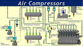
- 4. M a r i n e E n g i n e e r i n g K n o w l e d g e U E 2 3 1 | Y A S S E R B . A . F A R A G2 January 2021 Configurations 847
- 5. M a r i n e E n g i n e e r i n g K n o w l e d g e U E 2 3 1 | Y A S S E R B . A . F A R A G2 January 2021 848 Compression cycle
- 6. M a r i n e E n g i n e e r i n g K n o w l e d g e U E 2 3 1 | Y A S S E R B . A . F A R A G2 January 2021 Single stage single acting Single stage Single Stage Double Acting 849
- 7. M a r i n e E n g i n e e r i n g K n o w l e d g e U E 2 3 1 | Y A S S E R B . A . F A R A G2 January 2021 Multistaging 850
- 8. M a r i n e E n g i n e e r i n g K n o w l e d g e U E 2 3 1 | Y A S S E R B . A . F A R A G2 January 2021 P-V Diagram 851
- 9. M a r i n e E n g i n e e r i n g K n o w l e d g e U E 2 3 1 | Y A S S E R B . A . F A R A G2 January 2021 Intercooling effect 852
- 10. M a r i n e E n g i n e e r i n g K n o w l e d g e U E 2 3 1 | Y A S S E R B . A . F A R A G2 January 2021 𝜂𝜂𝑣𝑣= _______________________ Volumetric Efficiency Theoretical suction volume Vs Actual suction volume Vx 853
- 11. M a r i n e E n g i n e e r i n g K n o w l e d g e U E 2 3 1 | Y A S S E R B . A . F A R A G2 January 2021 854 Compressor Valves
- 12. M a r i n e E n g i n e e r i n g K n o w l e d g e U E 2 3 1 | Y A S S E R B . A . F A R A G2 January 2021 Compound Valves, why used in Air Compressor? • Give large area of opening and small amount of valve lift. • Improve Volumetric Efficiency, as valve open and close in minimum time. • Reduce bumping clearance. • Reduce wear and tear. 855 Compressor Valves
- 13. M a r i n e E n g i n e e r i n g K n o w l e d g e U E 2 3 1 | Y A S S E R B . A . F A R A G2 January 2021 Effects of leaking valves in Air Compressor: First Stage Suction: • Reduce air delivery • Reduce 2nd stage suction pressure • Unload the compressor • Increase running time. First Stage Delivery: • Reduce air delivery • Increase discharge temperature • Less air drawn in, due to high-pressure air leaking back into cylinder. 856 Compressor Valves
- 14. M a r i n e E n g i n e e r i n g K n o w l e d g e U E 2 3 1 | Y A S S E R B . A . F A R A G2 January 2021 Effects of leaking valves in Air Compressor: Second Stage Suction: • Reduce air delivery • High temperature & pressure in 2nd stage suction line • Increase running time Second Stage Delivery: • Reduce air delivery • Increase suction pressure in 2nd stage • Increase delivery pressure from 1st stage. • Back pressure from air bottle 857 Compressor Valves
- 15. M a r i n e E n g i n e e r i n g K n o w l e d g e U E 2 3 1 | Y A S S E R B . A . F A R A G2 January 2021 Compressor Valves How to check Air Compressor Efficiency? • Regular overhauling of valves done or not. • Check Air Bottle filling time. • Compare test results and records How to check Air Compressor capacity is sufficient? • Total no. of Air Compressors must be sufficient to fill the empty Air Bottle to maximum pressure within 1 hour. • Must be sufficient to start at least 12 times for Reversible Engine, and at least 6 times for Non-Reversible Engine. 858
- 16. M a r i n e E n g i n e e r i n g K n o w l e d g e U E 2 3 1 | Y A S S E R B . A . F A R A G2 January 2021 Safety devices on Main Air Compressor • Bursting Disc on Intercooler: (At water side) • Bursting Disc and Fusible Plug (121°C) on Aftercooler • Relief valves on LP and HP stages. (Set to lift at 10% rise above normal stage pressure.) • Automatic Moisture Drain Valve. • Cooling water supply failure alarm. • Low LO pressure alarm. • Relief valve on crankcase LO pump. • Delivery air HT cut out and alarm on Aftercooler outlet. (Max. 93°C) • LP discharge pressure 4 bars and HP discharge pressure 30 bar • Intercooler inlet air 130°C and intercooler outlet air 35°C • Aftercooler inlet air 130°C and Aftercooler outlet air 35°C: 859
- 17. M a r i n e E n g i n e e r i n g K n o w l e d g e U E 2 3 1 | Y A S S E R B . A . F A R A G2 January 2021 Bursting Disc • Fitted on the shell of Intercooler at waterside. • Relieves pressure if the tubes burst. • Rolled Copper Alloy and relief pressure is set while the disc is at softest condition. • Material tends to harden due to time and surrounding temperature, and set pressure also increased. • Bursting Disc needed to be annealed, to regain correct relief pressure 860
- 18. M a r i n e E n g i n e e r i n g K n o w l e d g e U E 2 3 1 | Y A S S E R B . A . F A R A G2 January 2021 Hazard of Dirty Filter • Very dirty filter or muffling a filter results in large pressure drop. • Air has to be compressed over higher range. • In extreme case, discharge air temperature may exceed flash point, or auto-ignition temperature resulting in an • As a safety against explosion, air temperature is limited to 93° Fusible Plug(121°C) or a High Temperature cut out (93°C) is provided on Compressor. 861
- 19. M a r i n e E n g i n e e r i n g K n o w l e d g e U E 2 3 1 | Y A S S E R B . A . F A R A G2 January 2021 Air receiver Safety devices on Main Air Bottle: 1. Fusible plug. 2. Pressure Relief Valve 3. Atmospheric Relief Valve. 4. Low Air Pressure alarm. 5. Automatic or remote control Moisture Drain Valve. 862
- 20. M a r i n e E n g i n e e r i n g K n o w l e d g e U E 2 3 1 | Y A S S E R B . A . F A R A G2 January 2021 Mountings 1. Fusible plug: • composition – Bismuth 50%, Tin 30%, Lead 20%, • Melting point: 220΄F (104.4΄C). Fitted at the reservoir’s bottom or on reservoir at ship side, when relief valve (safety valve) is not directly fitted on the reservoir. 2. Atmospheric relief valve: provided for back-up of fusible plug. In case of ER fire when CO₂ flooding is required, this valve is opened before evacuating ER. 3. Spring loaded safety valve: setting pressure: 32 bar (for 30 bar working pressure), with ≯ 10% rise in accumulation of pressure. May be fitted directly or with extension. 4. Compensation ring: when a hole is cut or machined in pressure vessel, higher stresses will subject to the material around the hole, and to reduce this, compensation rings are fitted. It is a flange on which a valve or fitting is usually mounted. 5. Manual Drain valve or Automatic Drain valve. 6. Pressure gauges. 7. Access doors. 8. Main starting air valve, auxiliary starting air valve, filling valve, service air or whistle air valve. 863