SlideShare une entreprise Scribd logo
1  sur  27
Dr. Y. Narasimha Murthy Ph.D
yayavaram@yahoo.com

UNIT-I DATA COMMUNICATIONS
Introduction: Data communications deals with

the transmission (sending and receiving) of

information between two locations by means of electrical signals. The two types of electrical
signals may be either

analog or digital. Digital Data communication is the name given to the

communication where exchange of information takes place in the form of 0s and 1s over some
transmission medium like a wire or wireless .
The effectness of a data communication system depends on three fundamental characteristics
.They are Delivery , Accuracy and Timeliness.
(i) Delivery: The system must deliver data to the correct destination. Data must be received by
the intended device or user and only by that device or user.
(ii).Accuracy :The system must deliver the data accurately .Data that have been altered in
transmission and left uncorrected must not be used.
(iii).Timeliness: The system must deliver the data in time.The data delivered late are useless .For
example in the case of audio and video ,timely delivery means ,delivering the data as they are
produced in the same order of production and without significant delay.This type of delivery is
called real-time transmission.
Components : A data communication system is made up of five basic components .They are
(i).Messages (ii).Sender (iii).Receiver (iv).Medium and (v).Protocol

(i) Message: The message is the data information to be communicated. It can be either text,
numbers or audio or video or any combination of these types.
(ii).Sender: The sender is the device that sends the data message. It can be a computer
,workstation ,telephone handset ,video camera etc..
1
Dr. Y. Narasimha Murthy Ph.D
yayavaram@yahoo.com

(iii) Receiver : The receiver is the device that receives the messages. It can be a computer,
workstation , telephone handset ,video camera or television etc.
(iv).Medium:The transmission medium is the physical path by which a message travels from
sender to receiver.It should be a twisted –pair wire ,co-axial cable,fiber optic cable or Radio
waves etc.
(v).Protocol: A protocol is a set of rules that govern the data communications.It represents an
arrangement between the communicating devices.Without a protocol ,two devices may be
connected but can not communicate.

Basic terms and concepts : In data communication mainly the data is being transmitted
between two devices namely transmitter and receiver. To understand this entire phenomena we
need to know about five basic concepts .They are
Line configuration
Topology
Transmission mode
Categories of Networks.
Internetworks.
LINE CONFIGURATION:
It refers to the way by which two or more communication devices are connected to a link.A link
is a physical communication pathway that transfers data from one device to another.
Based on the requirements, there are two possible line configurations.Point to point and multipoint
• Point- to-point communication: A point to point connection provides a dedicated link
between two devices.The total capacity of the link is used for the communication between these
two devices. In most point-to point actual length of wire or cable is used to connect the two
devices. For example the use of an infrared remote to change the channel in a Television
establishes a point-to-point contact between remote and T.V

2
Dr. Y. Narasimha Murthy Ph.D
yayavaram@yahoo.com

Similarly , in the case of voice communication using telephones, there is one calling party and
one called party. Hence the communication is point-to-point.
Multipoint : A multipoint or multi drop connection is one in which more than two specific
devices share a single link. In a multi-point configuration the capacity of the channel is shared
either spatially or temporally .If several devices are using the link simultaneously, they share it
spatially on the other hand many users are using the same link by turn it is a time share
connection.(means ,they share it temporally).

• Broadcasting: In a broadcasting system, there is a central location from which information is
sent to many recipients, as in the case of audio or video broadcasting. In a broadcasting system,
the listeners are passive, and there is no reverse communication path.

TOPOLOGY :
The topology defines how the devices (computers, printers..etc) are connected and how the data
flows from one device to another. There are two conventions while representing the topologies.
The physical topology defines how the devices are physically wired. The logical topology
defines how the data flows from one device to another.
Topologies are broadly categorized into i) Bus ii ) Ring iii) Star

iv) Mesh

3
Dr. Y. Narasimha Murthy Ph.D
yayavaram@yahoo.com

Mesh Topology : In a mesh topology, every device has a dedicated point-to-point link to every
other device. The term dedicated means that the link carries traffic only between the two devices
it connects. To find the number of physical links in a fully connected mesh network with n
nodes, we first consider that each node must be connected to every other node. Node 1 must be
connected to n - I nodes, node 2 must be connected to n – 1 nodes, and finally node n must be
connected to n - 1 nodes. We need n(n - 1) physical links. However, if each physical link allows
communication in both directions (duplex mode), we can divide the number of links by 2. In
other words, we can say that in a mesh topology, we need n(n -1) /2 duplex-mode links.

A mesh offers several advantages over other network topologies. First, the use of dedicated
links guarantees that each connection can carry its own data load, thus eliminating the traffic
problems that can occur when links are shared by multiple devices.
Second, a mesh topology is robust. If one link becomes unusable, it does not incapacitate the
entire system.
4
Dr. Y. Narasimha Murthy Ph.D
yayavaram@yahoo.com

Third, there is the advantage of privacy or security. When every message travels along a
dedicated line, only the intended recipient sees it. Physical boundaries prevent other users from
gaining access to messages.
Finally, point-to-point links make fault identification and fault isolation easy. Traffic can be
routed to avoid links with suspected problems. This facility enables the network manager to
discover the precise location of the fault and aids in finding its cause and solution.
The main disadvantages of a mesh are related to the amount of cabling and the number of I/O
ports required. First, because every device must be connected to every other device, installation
and reconnection are difficult. Second, the sheer bulk of the wiring can be greater than the
available space (in walls, ceilings, or floors) can accommodate.
Finally, the hardware required to connect each link (I/O ports and cable) can be prohibitively
expensive. For these reasons a mesh topology is usually implemented in a limited fashion, for
example, as a backbone connecting the main computers of a hybrid net work that can include
several other topologies.
One practical example of a mesh topology is the connection of telephone regional offices in
which each regional office needs to be connected to every other regional office.
Star Topology: In a star topology, each device has a dedicated point-to-point link only to a
central controller, usually called a hub. The devices are not directly linked to one another. Unlike
a mesh topology, a star topology does not allow direct traffic between devices. The controller
acts as an exchange: If one device wants to send data to another, it sends the data to the
controller, which then relays the data to the other connected device .A star topology is less
expensive than a mesh topology. In a star, each device needs only one link and one I/O port to
connect it to any number of others. This factor also makes it easy to install and reconfigure. Far
less cabling needs to be housed, and additions, moves, and deletions involve only one
connection: between that device and the hub. Other advantages include robustness. If one link
fails, only that link is affected. All other links remain active. This factor also lends itself to easy
fault identification and fault isolation. As long as the hub is working, it can be used to monitor
link problems and bypass defective links.
The main

disadvantage of a star topology is the dependency of the whole topology on one

single point, the hub. If the hub goes down, the whole system is dead. Although a star requires
5
Dr. Y. Narasimha Murthy Ph.D
yayavaram@yahoo.com

far less cable than a mesh, each node must be linked to a central hub. For this reason, often more
cabling is required in a star than in some other topologies (such as ring or bus).The star topology
is used in local-area networks (LANs),

Bus topology:
In a bus topology all devices are connected to the transmission medium as backbone. There must
be a terminator at each end of the bus to avoid signal reflections, which may distort the original
signal. Signal is sent in both directions, but some buses are unidirectional. Good for small
networks. Can be used for 10BASE5 (thick net), 10BASE2 (thin net) or 10BROAD36 (broad
band) co-axial bus standards.

Nodes are connected to the bus cable by drop lines and taps. A drop line is a connection running
between the device and the main cable. A tap is a connector that either splices into the main
cable or punctures the sheathing of a cable to create a contact with the metallic core. As a signal
travels along the backbone, some of its energy is transformed into heat. Therefore, it becomes
weaker and weaker as it travels farther and farther. For this reason there is a limit on the number
of taps a bus can support and on the distance between those taps.
Advantages of a bus topology include ease of installation. Backbone cable can be laid along the
most efficient path, then connected to the nodes by drop lines of various lengths. In this way, a
bus uses less cabling than mesh or star topologies. In a star, for example, four network devices in
6
Dr. Y. Narasimha Murthy Ph.D
yayavaram@yahoo.com

the same room require four lengths of cable reaching all the way to the hub. In a bus, this
redundancy is eliminated. Only the backbone cable stretches through the entire facility. Each drop
line has to reach only as far as the nearest point on the backbone.
Disadvantages of bus topology are difficulties in reconnection and fault isolation. A bus is usually
designed to be optimally efficient at installation. It can therefore be difficult to add new devices.
Signal reflection at the taps can cause degradation in quality. This degradation can be controlled by
limiting the number and spacing of devices connected to a given length of cable. Adding new devices
may therefore require modification or replacement of the backbone.
The other disadvantage is , a fault or break in the bus cable stops all transmission, even between
devices on the same side of the problem. The damaged area reflects signals back in the direction of
origin, creating noise in both directions.
Bus topology was the one of the first topologies used in the design of early local area networks.
Ethernet LANs can use a bus topology, but they are less popular.

Ring Topology : In a ring topology, each device has a dedicated point-to-point connection with
only the two devices on either side of it. A signal is passed along the ring in one direction, from
device to device, until it reaches its destination. Each device in the ring incorporates a repeater.
When a device receives a signal intended for another device, its repeater regenerates the bits and
passes them along. A ring is relatively easy to install and reconfigure. Each device is linked to
only its immediate neighbors (either physically or logically). To add or delete a device requires
changing only two

connections. The only constraints are media and traffic considerations

(maximum ring length and number of devices). In addition, fault isolation is simplified.
Generally in a ring, a signal is circulating at all times. If one device does not receive a signal
within a specified period, it can issue an alarm. The alarm alerts the network operator to the
problem and its location. However, unidirectional traffic can be a disadvantage. In a simple ring,
a break in the ring (such as a disabled station) can disable the entire network. This weakness can
be solved by using a dual ring or a switch capable of closing off the break.

7
Dr. Y. Narasimha Murthy Ph.D
yayavaram@yahoo.com

Ring topology was prevalent when IBM introduced its local-area network Token Ring. With the
advent of higher-speed LANs this topology has become less useful.

TRANSMISSION MODE :The term transmission mode is used to define the direction of signl
flow between two linked devices.There are three types of transmission modes.They are Simplex ,
Half Duplex and Full-Duplex.
Simplex: In simplex mode communication is unidirectional .i.e only one of the two devices on a
link can transmit data and the other will only receive the data.As shown below a computer
always sends the data and the monitor only receives the data.

Similarly a key board always receives the data from the computer and computers send the data
to the keyboard.
Half Duplex: In half duplex both the devices can transmit and receive the data in the data
communication. But not at the same time. When one device is sending the data the other will be
receiving and vice versa. The use of a walkie-talkie by police and army personal is an example
for this half-duplex transmission.

The Half duplex method is like a one lane road with two directional traffic. While cars are
travelling one direction , cars going the other direction must wait. In a half Duplex transmission
the entire capacity of a channel is taken over by which ever of the two devices is transmitting at
the time.
Full Duplex : In full duplex mode (also called Duplex) both stations can transmit and receive
data simultaneously. One common example is mobile phone or telephone line .
8
Dr. Y. Narasimha Murthy Ph.D
yayavaram@yahoo.com

The full duplex mode is like a two way street with traffic following in both directions at the same
time .In full duplex ,the signals going in either direction share the capacity of the link. This
sharing can occur in two ways. Either the link must contain two physically separate transmission
paths .One for sending and the other for receiving .or the capacity of the channel is divided
between signals travelling in both directions.
MODEMS:
The term modem stands for Modulator & De-Modulator .The most familiar type of Data
Communication Equipment (DTE) is a Modem. The term modem is a composite word that refers
to the two functional entities that make up the device:

a signal modulator and a signal

demodulator. A modulator converts a digital signal into an analog signal using ASK, FSK, PSK,
or QAM. A demodulator converts an analog signal into a digital signal. While a demodulator
resembles an analog-to-digital converter, it is not in fact a converter of any kind. It does not
sample a signal to create a digital facsimile; it merely reverses the process of modulation-that is,
it performs demodulation.
The modem consists of
• Interface circuitry for linking with the host PC
• Circuits to prepare data for transmission by adding the proper start, stop, and parity bits.
• The modulator that converts PCs digital signals into analog signals.
• The user interface that gives you commands of the modem's operation.

9
Dr. Y. Narasimha Murthy Ph.D
yayavaram@yahoo.com

In the above diagram the two PCs are the DTEs i.e data Terminal Equipments. The Modems are
DCEs. The demodulator takes theASK,FSK, PSK or QAM signal and decodes into a suitable
form for a computer.It then relays the resulting digital signal to the receiving computer via the
internet .Each DCE must be compatible with both its own DTE and other DTEs.
Modem Standards

The two modem standards are

Bell modems and ITU· modems. Bell Modems The first

commercial modems were produced by the Bell Telephone Company in early 1970s. As the first
and, for a long time, lone manufacturer in the marketplace, Be defined the development of the
technology and provided a de facto standard upon which subsequent manufacturers have built.
Today there are dozens of companies producing hundreds of different types of modems
worldwide. As complex and powerful as many models have become, they all evolved from the
original and. relatively simple first models from Bell.
The Bell 212 series modems have two speeds. The option of a second speed allows for
compatibility with a wider number of systems. Both speeds operate in full-duplex mode over
switched telephone lines. The slower speed, 300 bps, uses FSK
The 201 series modems operate in either half-duplex mode over two-we switched lines or fullduplex mode over four-wire leased lines. The entire bandwidth over two-wire line is dedicated to
a single direction of transmission. Four-wire lines allow for two completely separate channels,
one in each direction, to be processed through single modem on each end.
ITU-T Modem Standards
Now a days most popular modems available are based on standards published by the ITU-T.
These modems can be divided into two groups: those that are essentially equivalent to Bell series
modems-for example, V.21 is similar to Bell modem 103-and those that are not.
10
Dr. Y. Narasimha Murthy Ph.D
yayavaram@yahoo.com

Those ITU- T modems that are Bell series compatible are given below table with their Bell
equivalents.
ITU-T

Bell

Baud Rate

Bit Rate

Modulation

V.21

103

300

300

FSK

V.22
V.23
V.26
V.27
V.29

212
202
201
208
209

600
1200
1200
1600
2400

1200
1200
2400
4800
9600

4-PSK
FSK
4-PSK
8-PSK
16-QAM

Intelligent Modems
Intelligent

modems contain software to support a number of additional functions, such as

automatic

answering and dialing. Intelligent modems were first introduced by Hayes

Microcomputer Products, Inc. More recently, other manufacturers have come out with

Hayes

compatible modems. Instructions in the Hayes and Hayes-compatible modems are called AT
commands (AT is short for attention).
56K MODEMS :
Traditional modems have a limitation on the data rate (maximum of 33.6 Kbps), However, new
modems, with a bit rate of 56,000 bps, called 56K modems, are now on the market. These
modems may be used only if one party is using digital signaling (such as through an Internet
provider). They area symmetrical in that the downloading (flow of data from the Internet
provider to the PC) is a maximum of 56 Kbps, while the uploading (flow of data from the PC to
the Internet provider) can be a maximum of 33.6 Kbps. If one side is an Internet provider and
the signal does not have to pass through a PCM converter, quantization is eliminated in one
direction and the data rate can be increased to 56 Kbps .
Encoding and Modulating :
In the process of data communication the data must be transformed into signals to send them
from one place to another. Data stored in a computer is in the form of 0s and 1s.To transform
this data from one place to another place , it must be converted into digital signals.This is called
Encoding digital data into digital signal or digital to digital conversion. The process of
converting analog signal into digital signal is called analog to digital conversion or digitizing an
analog signal.
11
Dr. Y. Narasimha Murthy Ph.D
yayavaram@yahoo.com

The process of converting the digital signal into analog signal is called digital to analog
conversion or modulating a digital signal.
The process of sending an analog signal over long distances using a high frequency carrier signal
is called analog to analog conversion or modulating an analog signal.

Digital to Digital Encoding: It is the representation of a digital information by a digital signal
.In this process of encoding the binary 1s and 0s generated by a computer are translated into a
sequence of voltage pulses that can be transmitted over a cable or wire. This process is shown in
the diagram below.

There are three types of digital encodings. Unipolar ,Polar and Bi-polar.
Uni-polar : Unipolar encoding uses only one level of value. i.e in a uni-polar scheme, all the
signal levels are on one side of the time axis, either above or below.

12
Dr. Y. Narasimha Murthy Ph.D
yayavaram@yahoo.com

The uni-polar encoding has two problems .One is DC component and the other is
synchronization. Due to these limitations ,this encoding is not widely used.
The DC component problem arises because the average amplitude of a uni-polar encoded signal
is non- zero. This causes what is called a direct current component. When a signal contains a DC
component, it cannot travel through the media that cannot handle DC components.
The Synchronization problem in uni-polar encoding occur when ever the data stream includes a
long uninterrupted series of 1s or 0s. Compared to polar encoding this scheme is very costly.
Polar Schemes:
In polar schemes, the voltages are on the both sides of the time axis. For example, the voltage
level for 0 can be positive and the voltage level for I can be negative.The popular Polar encoding
techniques are Non-return zero(NRZ),Return to Zero(RZ) and bi-phase. The bi-phase refers to
two methods.One is Manchester

used in

Ethernet

LAN and the second is Differential

Manchester used by token rings LANs.
Types of polar encodings is shown below.

13
Dr. Y. Narasimha Murthy Ph.D
yayavaram@yahoo.com

Non-Return-to-Zero (NRZ) :
In polar NRZ encoding, two levels of voltage amplitude are used. There are two versions of
polar NRZ: NRZ-Land NRZ-I, as shown in Figure below. The figure also shows the value of r,
the average baud rate, and the bandwidth. In the first variation, NRZ-L (NRZ-Level), the level of
the voltage determines the value of the bit. In the second variation, NRZ-I (NRZ-Invert), the
change or lack of change in the level of the voltage determines the value of the bit. If there is no
change, the bit is 0; if there is a change, the bit is 1. NRZ-L and NRZ-J both have a DC
component problem.

The synchronization problem (sender and receiver clocks are not synchronized) also exists in
both the schemes. This problem is more serious in NRZ-L than in NRZ-I. While a long sequence
of datas can cause a problem in both schemes, a long sequence of 1s affects only NRZ-L.
Another problem with NRZ-L occurs when there is a sudden change of polarity in the system.
For example, if twisted-pair cable is the medium, a change in the polarity of the wire results in
all 0s interpreted as I s and all I s interpreted 0s . NRZ-I does not have this problem. Both
schemes have an average signal rate of N/2 Bd.
Return to Zero (RZ)
The main problem with NRZ encoding occurs when the sender and receiver clocks are not
synchronized. The receiver does not know when one bit has ended and the next bit is starting.
Hence the Return-to-zero (RZ) scheme is used. This scheme uses three values: positive,
negative, and zero. In RZ, the signal changes not between bits but during the bit. In Figure
below we see that the signal goes to 0 in the middle of each bit. It remains there until the
beginning of the next bit. The main disadvantage of RZ encoding is that it requires two signal
changes to encode a bit and therefore occupies greater bandwidth. This scheme has no DC
component problem

14
Dr. Y. Narasimha Murthy Ph.D
yayavaram@yahoo.com

. But the problem is the complexity : RZ uses three levels of voltage, which is more complex to
create . As a result of all these deficiencies, the scheme is not used today. Instead, the betterperforming schemes like Manchester and differential Manchester schemes are used.
Biphase:
The best solution for the problem of synchronization is the Bi-phase encoding.This bi-phase
encoding consists of two important encodings namely Manchester and Differential Manchester
encodings . Manchester scheme is the resultant of the idea of RZ (transition at the middle of the
bit) and the idea of NRZ-L . In Manchester encoding, the duration of the bit is divided into two
halves. The voltage remains at one level during the first half and moves to the other level in the
second half. The transition at the middle of the bit provides synchronization. On the other hand
Differential Manchester, combines the ideas of RZ and NRZ-I. There is always a transition at the
middle of the bit, but the bit values are determined at the beginning of the bit. If the next bit is 0,
there is a transition; if the next bit is 1, there is none. Figure below shows both Manchester and
differential Manchester encodings.

15
Dr. Y. Narasimha Murthy Ph.D
yayavaram@yahoo.com

In Manchester and differential Manchester encoding, the transition at the middle of the bit is
used for synchronization. The Manchester scheme overcomes several problems associated with
NRZ-L, and differential Manchester overcomes several problems associated with NRZ-I.
First, there is no baseline wandering. There is no DC component because each bit has a positive
and negative voltage contribution. The only drawback is the signal rate. The signal rate for
Manchester and differential Manchester is double that for NRZ. The reason is that there is
always one transition at the middle of the bit and maybe one transition at the end of each bit.
Manchester and differential Manchester schemes are also called bi-phase schemes.
Channel capacity
The maximum rate at which data can be transmitted over a communication channel under given
conditions is referred as the channel capacity. Four important parameters are related in the
evaluation of channel capacity.
• Data rate: The rate at which data can be transmitted. Measured in bits per second
• Bandwidth: The bandwidth of the transmitted signal. Measured in cycles per second (Hz).
• Noise: The average level of unwanted signals over communication path. Expressed as the ratio
between signal and noise.
• Error rate: The rate at which error can occur.
The Channel capacity (in cycles per second) is given by Shannon’s theorem. According to
Shannon’s theorem
C = B log2 (1+SNR)

Where C is channel capacity in Cycles per second and this is error free capacity ; B is the
bandwidth in Hertz and SNR = 10 log10 (Signal power/Noise power) known as signal to noise
ratio.
Here the SNR ratio assumes only white noise (thermal noise) where as other noise like impulse
noise, attenuation noise and delay noise are not taken into account. Hence the actual value of
channel capacity differs from the estimated value
TRANSMISSION IMPAIRMENT:
When signals travel through imperfect transmission media, the imperfection causes signal
impairment. This means that the signal at the beginning of the medium is not the same as the
16
Dr. Y. Narasimha Murthy Ph.D
yayavaram@yahoo.com

signal at the end of the medium. What is sent is not what is received. The impairment of signals
is mainly caused due to attenuation, distortion, and noise in the medium.

Attenuation
Attenuation means a loss of energy. When a signal, simple or composite, travels through a
medium, it loses some of its energy in overcoming the resistance of the medium. That is why a
wire carrying electric signals gets warm . Some of the electrical energy in the signal is converted
to heat. To compensate for this loss, amplifiers are used to amplify the signal.

Distortion : Distortion means that the signal changes its form or shape. Distortion can occur in a
composite signal made of different frequencies. Each signal component has its own propagation
speed (see the next section) through a medium and, therefore, its own delay in arriving at the
final destination. Differences in delay may create a difference in phase if the delay is not exactly
the same as the period duration. In other words, signal components at the receiver have phases
different from what they had at the sender. The shape of the composite signal is therefore not the
same. Figure below shows the effect of distortion on a composite signal.

17
Dr. Y. Narasimha Murthy Ph.D
yayavaram@yahoo.com

Noise
Noise is another cause of impairment. Several types of noise, such as thermal noise, induced
noise, crosstalk, and impulse noise, may corrupt the signal. Thermal noise is the random motion
of electrons in a wire which creates an extra signal not originally sent by the transmitter. Induced
noise comes from sources such as motors and appliances. These devices act as a sending
antenna, and the transmission medium acts as the receiving antenna. Crosstalk is the effect of
one wire on the other. One wire acts as ascending antenna and the other as the receiving antenna.
Impulse noise is a spike (a signal with high energy in a very short time) that comes from power
lines, lightning, and so on.

Signal-to-Noise Ratio (SNR)
The signal-to-noise ratio is defined as SNR = average signal power / average noise power.

SNR is actually the ratio of what is wanted (signal) to what is not wanted (noise). A high SNR
means the signal is less corrupted by noise; a low SNR means the signal is more corrupted by
noise. Because SNR is the ratio of two powers, it is often described in decibel units
SNR dB, defined as
SNRdB = 10 log 10SNR.

18
Dr. Y. Narasimha Murthy Ph.D
yayavaram@yahoo.com

Broadband System
A "broadband" system has the capability for transmitting a broad range of analog frequencies
over a single cable, Broadband LANs work in a similar way that cable television works.
Broadband LANs transmit multiple radio frequency signals on the same cable, usually coaxial or
sometimes fiber. This ability to send many types of communication simultaneously over the
same cable, including voice, video, and data, distinguishes broadband LANs from the other
common baseband LANs.
For this operation, broadband LANs use the technique called frequency division multiplexing.
Each channel in a broadband system is separated from the adjacent channel by a guard band, a
frequency range over which no data will be transmitted. The simplest broadband LAN will be
split into two channels, one for inbound data, one for outbound. Each

of these gross channels

may be split into two or many more channels.
Broadband LANs use a tree-and-branch topology. The root of the tree is the head end, or central
re- transmission facility. The trunk cable is attached to this root.
Baseband System:
Baseband methodology allows several devices to share a cable by means of a time-sharing
technique. Each device is assigned a specific time slot some thousandths or millionths of a
second in length in which to transmit. Only one device can transmit in a given time interval.This
technique is called time division multiplexing. Baseband transmission is associated with specific
network and performance characteristics.
(a) Many types of media can be used, such as twisted pair, coaxial cable, and fiber optics.
(b).There must be a protocol included in the network to assign time slots and provide access to
the network.
(c) . Modems are not required to connect devices to the cable when communicating digital
information.
(d).Any number of devices can be used for transmission or reception of information, without the
addition of complex equipment, as long as there are enough slots available.
Comparison
Broadband (analog) transmission is generally regarded as a higher throughput technique because
of the ability to simultaneously transmit multiple signals over a single cable.
19
Dr. Y. Narasimha Murthy Ph.D
yayavaram@yahoo.com

Baseband is a highly efficient way of moving data from one piece of digital equipment to
another. Hundreds of millions of data bits per second can move along the cable, with no
slowdowns for analog conversion. These data bits, however, must move single file, and there is a
finite limit to the total number of bits that can be transmitted during any given time period.
The transmission rate advantage of broadband transmission is rapidly disappearing, however,
with recent advances in digital technology, particularly in fiber optics, allowing digital baseband
transmissions to rival, and even exceed broadband analog transmission speed.
Baseband technology has benefitted substantially from continuing advances in integrated circuit
technology. Installation, device connection, and control of communication traffic are all less
expensive for digital networks than for analog networks.
Broadband cable per foot is less expensive than baseband. The additional hardware needed
(modems and directional couplers) to modulate the data signal for analog transmission from
point to point and the more complex design engineering required will however raise the cost of
installing broadband.
MULTIPLEXING : Multiplexing is the techniques that allows the simultaneous transmission
of multiple signals across a single data link .As data and telecommunications use increases, so
does traffic. The figure below shows the basic format of a multiplexed

system. The lines on

the left direct their transmission streams to a multiplexer (MUX), which combines them into a
single stream (many-to one).At the receiving end, that stream is fed into a de-multiplexer
(DEMUX), which separates the stream back into its component transmissions (one-to-many) and
directs them to their corresponding lines. In the figure, the word link refers to the physical path.
The word channel refers to the portion of a link that carries a transmission between a given pair
of lines. One link can have many (n) channels.
There are three basic multiplexing techniques: frequency-division multiplexing, wavelengthdivision multiplexing, and time-division multiplexing. The first two techniques designed for
analog signals, the third one is , for digital signals

20
Dr. Y. Narasimha Murthy Ph.D
yayavaram@yahoo.com

Frequency-Division Multiplexing : Frequency-division multiplexing (FDM) is an analog
technique that can be applied when the bandwidth of a link (in hertz) is greater than the
combined bandwidths of the signals to be transmitted. In FDM, signals generated by each
sending device modulate different carrier frequencies. These modulated signals are then
combined into a single composite signal that can be transported by the link. Carrier frequencies
are separated by sufficient bandwidth to accommodate the modulated signal. These bandwidth
ranges are the channels through which the various signals travel. Channels can be separated by
strips of unused bandwidth-guard bands-to prevent signals from overlapping. In addition, carrier
frequencies must not interfere with the original data frequencies.
A very common application of FDM is AM and FM radio broadcasting. Radio uses the air as the
transmission medium. A special band from 530 to 1700 kHz is assigned to AM radio. All radio
stations need to share this band. Each AM station needs 10kHz of bandwidth. Each station uses a
different carrier frequency, which means it is shifting its signal and multiplexing. The signal that
goes to the air is a combination of signals. A receiver receives all these signals, but filters (by
tuning) only the one which is desired. Without multiplexing, only one AM station could
broadcast to the common link, the air.
The same concept is also used in FM broadcasting. But the , FM has a wider band of 88 to 108
MHz , because each station needs a bandwidth of 200 kHz.
Another common use of FDM is in television broadcasting. Each TV channel has its own
bandwidth of 6 MHz. The first generation of cellular telephones (still in operation) also uses
FDM
Wavelength-Division Multiplexing: Wavelength-division multiplexing (WDM) is designed to
use the high-data-rate capability of fiber-optic cable. The optical fiber data rate is higher than the
21
Dr. Y. Narasimha Murthy Ph.D
yayavaram@yahoo.com

data rate of metallic transmission cable. Using a fiber-optic cable for one single line will waste
the available bandwidth. So, multiplexing is used which allows to combine several lines into
one. WDM is conceptually the same as FDM, except that the multiplexing and de-multiplexing
involve optical signals transmitted through fiber-optic channels. The idea is combining different
signals of different frequencies. The difference is that the frequencies are very high .Figure
below gives a conceptual view of a WDM multiplexer and de-multiplexer. Very narrow bands
of light from different sources are combined to make a wider band of light. At the receiver, the
signals are separated by the de-multiplexer.

Although WDM technology is very complex, the basic idea is very simple. Multiple light sources
are combined into one single light at the multiplexer and do the reverse at the de-multiplexer.A
multiplexer can be made to combine several input beams of light, each containing a narrow band
of frequencies, into one output beam of a wider band of frequencies. A de-multiplexer can be
made to reverse the process.

The application of WDM is the SONET network in which multiple optical fiber lines are
multiplexed and de-multiplexed. A new method, called dense WDM (DWDM), can multiplex a
very large number of channels by spacing channels very close to one another. It achieves a
greater efficiency than ordinary WDM.

22
Dr. Y. Narasimha Murthy Ph.D
yayavaram@yahoo.com

Demultiplexing Process : The de-multiplexer uses a series of filters to decompose the
multiplexed signal into its constituent component signals. The individual signals are then passed
to a demodulator that separates them from their carriers and passes them to the output lines.
Error Detection and Correction :
During the transmission of data from one point to other there is every possibility that the data
may be corrupted and errors may occur. The data transfer through a Network must be always
with acceptable accuracy. So, these data errors must be detected and corrected for a good data
communication. Some applications can tolerate a small level of error. For example, random
errorsin audio or video transmissions may be tolerable, but when we transfer text, we expect a
very high level of accuracy.
Types of Errors
The errors in data communication are divided into two types.(i)Single Bit Errors and (ii) Burst
errors.
Single Bit Errors:
Whenever bits flow from one point to another, they are subject to unpredictable changes due to
interference. This interference can change the shape of the signal. In a single-bit error, a 0 is
changed to a 1 or a 1 to a 0.
The term single-bit error means that only 1 bit of a given data unit (such as a byte, character, or
packet) is changed from 1 to 0 or from 0 to 1.

The figure above shows the effect of a single-bit error on a data unit. To understand the impact
of the change, imagine that each group of 8 bits is an ASCII character with a 0 bit added to the
left. In the above figure 10.1,00000010 (ASCII STX) was sent, meaning start of text, but
00001010 (ASCII LF) was received, meaning line feed.
Single-bit errors are the least likely type of error in serial data transmission. For example let us ,
imagine data sent at 1 Mbps. This means that each bit lasts only 1/1,000,000 s, or 1µs. For a
single-bit error to occur, the noise must have a duration of only 1µs, which is very rare because
noise normally lasts much longer than this.
23
Dr. Y. Narasimha Murthy Ph.D
yayavaram@yahoo.com

Burst Error
The term burst error means that 2 or more bits in the data unit have changed from 1 to 0 or from
0 to 1.Here a burst of data is being corrupted and not a single bit.
In the figure below

the effect of a burst error on a data unit is shown. In this case,

100010001000011 was sent, but 0101110101100011 was received. Note that a burst error does
not necessarily mean that the errors occur in consecutive bits. The length of the burst is measured
from the first corrupted bit to the last corrupted bit. Some bits in between may not have been
corrupted.

A burst error is more likely to occur than a single-bit error. The duration of noise is normally
longer than the duration of 1 bit, which means that when noise affects data, it affects a set of bits.
The number of bits affected depends on the data rate and duration of noise. For example, if we
are sending data at I kbps, a noise of 11100 s can affect 10 bits; if we are sending data at 1 Mbps,
the same noise can affect 10,000 bits.

Redundancy:
The important concept in detecting or correcting errors is redundancy. To be able to detect or
correct errors, we need to send some extra bits with our data. These redundant bits are added by
the sender and removed by the receiver. Their presence allows the receiver to detect or correct
corrupted bits.
The correction of errors is more difficult than the detection. In error detection, we are looking
only to see if any error has occurred. The answer is a simple yes or no. We are not even
interested in the number of errors. A single-bit error is the same for us as a burst error. In error
24
Dr. Y. Narasimha Murthy Ph.D
yayavaram@yahoo.com

correction, we need to know the exact number of bits that are corrupted and more importantly,
their location in the message. The number of the errors and the size of the message are important
factors. If we need to correct one single error in an 8-bit data unit, we need to consider eight
possible error locations; if we need to correct two errors in a data unit of the same size, we need
to consider 28 possibilities. The difficulty of the receiver in finding 10 errors in a data unit of
1000 bits can be clearly understood from the above example.
There are two main methods of error correction. Forward error correction is the process in which
the receiver tries to guess the message by using redundant bits. This is possible, as we see later,
if the number of errors is small. Correction by retransmission is a technique in which the receiver
detects the occurrence of an error and asks the sender to resend the message. Resending is
repeated until a message arrives that the receiver believes is error-free.
Coding
Redundancy is achieved through various coding schemes. The sender adds redundant bits
through a process that creates a relationship between the redundant bits and the actual data bits.
The receiver checks the relationships between the two sets of bits to detect or correct the errors.
The ratio of redundant bits to the data bits and the robustness of the process are important factors
in any coding scheme. Figure below shows the general idea of coding. We can divide coding
schemes into two broad categories: block coding and convolution coding.
Block Coding
In block coding, the message is divided into blocks, each of k bits, called data words. And r
redundant bits are added to each block to make the length n = k + r. The resulting n-bit blocks
are called code words. With k bits, a combination of 2k data words are created ; with n bits, we
can create a combination of 2n code words. Since n > k, the number of possible code words is
larger than the number of possible data words.The block coding process is one-to-one ; the same
data word is always encoded as the same code word. This means that 2n - 2k code words are not
used which are invalid or illegal.

25
Dr. Y. Narasimha Murthy Ph.D
yayavaram@yahoo.com

Error Detection :
In block coding the receiver can detect a change in the original code word and the error can be
detected if the following conditions are satisfied.
The receiver has (or can find) a list of valid code words.
The original codeword has changed to an invalid one.

The sender creates code words out of data words by using a generator that applies the rules and
procedures of encoding . Each codeword sent to the receiver may change during transmission. If
the received codeword is the same as one of the valid code words, the word is accepted; the
corresponding data word is extracted for use. If the received code word is not valid, it is
discarded. However, if the codeword is corrupted during transmission but the received word still
matches a valid codeword, the error remains undetected. This type of coding can detect only
single errors. Two or more errors may remain undetected.
Cyclic Redundancy Check (CRC):
CRC is a category of error correction in data transmission using cyclic codes ,which is called the
cyclic redundancy check (CRC) .This CRC is used in networks such as LANs and WANs. One of
26
Dr. Y. Narasimha Murthy Ph.D
yayavaram@yahoo.com

the advantages of a cyclic code is that the encoder and decoder can easily and inexpensively
implemented in hardware by using a handful of electronic devices. Also, a hardware
implementation increases the rate of check bit and syndrome bit calculation.

Reference: Data Communications and Networking, Second Edition ,by Behrouz A. Forouzan.

27

Contenu connexe

Tendances

Chapter 4 data link layer
Chapter 4 data link layerChapter 4 data link layer
Chapter 4 data link layerNaiyan Noor
 
Multiplexing in mobile computing
Multiplexing in mobile computingMultiplexing in mobile computing
Multiplexing in mobile computingZituSahu
 
Common protocols
Common protocolsCommon protocols
Common protocolsMr SMAK
 
Transmission media (data communication)
Transmission media (data communication)Transmission media (data communication)
Transmission media (data communication)Pritom Chaki
 
WSN NETWORK -MAC PROTOCOLS - Low Duty Cycle Protocols And Wakeup Concepts – ...
WSN NETWORK -MAC PROTOCOLS - Low Duty Cycle Protocols And Wakeup Concepts –  ...WSN NETWORK -MAC PROTOCOLS - Low Duty Cycle Protocols And Wakeup Concepts –  ...
WSN NETWORK -MAC PROTOCOLS - Low Duty Cycle Protocols And Wakeup Concepts – ...ArunChokkalingam
 
Wireless transmission
Wireless transmissionWireless transmission
Wireless transmissionRajapriya82
 
wireless network IEEE 802.11
 wireless network IEEE 802.11 wireless network IEEE 802.11
wireless network IEEE 802.11Shreejan Acharya
 
Introduction to switching & circuit switching
Introduction to switching & circuit switchingIntroduction to switching & circuit switching
Introduction to switching & circuit switchingDr Rajiv Srivastava
 
TCP/IP Network ppt
TCP/IP Network pptTCP/IP Network ppt
TCP/IP Network pptextraganesh
 
Mobile Computing (Part-1)
Mobile Computing (Part-1)Mobile Computing (Part-1)
Mobile Computing (Part-1)Ankur Kumar
 
Networking and Internetworking Devices
Networking and Internetworking DevicesNetworking and Internetworking Devices
Networking and Internetworking Devices21viveksingh
 
Introduction To Mobile Computing
Introduction To Mobile ComputingIntroduction To Mobile Computing
Introduction To Mobile ComputingMadhuri Badgujar
 
User datagram protocol (udp)
User datagram protocol (udp)User datagram protocol (udp)
User datagram protocol (udp)Ramola Dhande
 
basic networking
basic networkingbasic networking
basic networkingAnmol Bagga
 
Powerpoint for data communication
Powerpoint for data communication Powerpoint for data communication
Powerpoint for data communication samanthaanderson21
 

Tendances (20)

Transport layer
Transport layer Transport layer
Transport layer
 
Chapter 4 data link layer
Chapter 4 data link layerChapter 4 data link layer
Chapter 4 data link layer
 
Media Access Control
Media Access ControlMedia Access Control
Media Access Control
 
Multiplexing in mobile computing
Multiplexing in mobile computingMultiplexing in mobile computing
Multiplexing in mobile computing
 
Common protocols
Common protocolsCommon protocols
Common protocols
 
Multiplexing
MultiplexingMultiplexing
Multiplexing
 
Transmission media (data communication)
Transmission media (data communication)Transmission media (data communication)
Transmission media (data communication)
 
WSN NETWORK -MAC PROTOCOLS - Low Duty Cycle Protocols And Wakeup Concepts – ...
WSN NETWORK -MAC PROTOCOLS - Low Duty Cycle Protocols And Wakeup Concepts –  ...WSN NETWORK -MAC PROTOCOLS - Low Duty Cycle Protocols And Wakeup Concepts –  ...
WSN NETWORK -MAC PROTOCOLS - Low Duty Cycle Protocols And Wakeup Concepts – ...
 
Wireless transmission
Wireless transmissionWireless transmission
Wireless transmission
 
wireless network IEEE 802.11
 wireless network IEEE 802.11 wireless network IEEE 802.11
wireless network IEEE 802.11
 
Introduction to switching & circuit switching
Introduction to switching & circuit switchingIntroduction to switching & circuit switching
Introduction to switching & circuit switching
 
TCP/IP Network ppt
TCP/IP Network pptTCP/IP Network ppt
TCP/IP Network ppt
 
TCP IP Addressing
TCP IP AddressingTCP IP Addressing
TCP IP Addressing
 
Osi model
Osi modelOsi model
Osi model
 
Mobile Computing (Part-1)
Mobile Computing (Part-1)Mobile Computing (Part-1)
Mobile Computing (Part-1)
 
Networking and Internetworking Devices
Networking and Internetworking DevicesNetworking and Internetworking Devices
Networking and Internetworking Devices
 
Introduction To Mobile Computing
Introduction To Mobile ComputingIntroduction To Mobile Computing
Introduction To Mobile Computing
 
User datagram protocol (udp)
User datagram protocol (udp)User datagram protocol (udp)
User datagram protocol (udp)
 
basic networking
basic networkingbasic networking
basic networking
 
Powerpoint for data communication
Powerpoint for data communication Powerpoint for data communication
Powerpoint for data communication
 

En vedette

Data communication - Lecture-01
Data communication - Lecture-01 Data communication - Lecture-01
Data communication - Lecture-01 Sehrish Rafiq
 
Basic Concepts in Data Communication DC1
Basic Concepts in Data Communication DC1Basic Concepts in Data Communication DC1
Basic Concepts in Data Communication DC1koolkampus
 
Data communications-concepts
Data communications-conceptsData communications-concepts
Data communications-conceptsWBUTTUTORIALS
 
Chapter4frequencymodulation 120317021055-phpapp01
Chapter4frequencymodulation 120317021055-phpapp01Chapter4frequencymodulation 120317021055-phpapp01
Chapter4frequencymodulation 120317021055-phpapp01Rj Egnisaban
 
Presentation on data communication
Presentation on data communicationPresentation on data communication
Presentation on data communicationHarpreet Dhaliwal
 
Data communication (simple explanation)
Data communication (simple explanation)Data communication (simple explanation)
Data communication (simple explanation)Twist Akid Sultan
 
Carrier Ethernet - What and Why
Carrier Ethernet - What and Why  Carrier Ethernet - What and Why
Carrier Ethernet - What and Why Anuradha Udunuwara
 
ระบบเครือข่าย LAN - ETHERNET
ระบบเครือข่าย LAN - ETHERNETระบบเครือข่าย LAN - ETHERNET
ระบบเครือข่าย LAN - ETHERNETAdisak Kammungkun
 
Pure Aloha and Slotted Aloha
Pure Aloha and Slotted AlohaPure Aloha and Slotted Aloha
Pure Aloha and Slotted AlohaChun-Kang Luo
 
Data communication and network Chapter -1
Data communication and network Chapter -1Data communication and network Chapter -1
Data communication and network Chapter -1Zafar Ayub
 
Chapter 1: Introduction to Data Communication and Networks
Chapter 1: Introduction to Data Communication and NetworksChapter 1: Introduction to Data Communication and Networks
Chapter 1: Introduction to Data Communication and NetworksShafaan Khaliq Bhatti
 
Chapter 4 frequency modulation
Chapter 4 frequency modulationChapter 4 frequency modulation
Chapter 4 frequency modulationHattori Sidek
 
Multiple Access Protocal
Multiple Access ProtocalMultiple Access Protocal
Multiple Access Protocaltes31
 

En vedette (16)

Ch 13
Ch 13Ch 13
Ch 13
 
Data communication - Lecture-01
Data communication - Lecture-01 Data communication - Lecture-01
Data communication - Lecture-01
 
Basic Concepts in Data Communication DC1
Basic Concepts in Data Communication DC1Basic Concepts in Data Communication DC1
Basic Concepts in Data Communication DC1
 
Data communications-concepts
Data communications-conceptsData communications-concepts
Data communications-concepts
 
Chapter4frequencymodulation 120317021055-phpapp01
Chapter4frequencymodulation 120317021055-phpapp01Chapter4frequencymodulation 120317021055-phpapp01
Chapter4frequencymodulation 120317021055-phpapp01
 
Presentation on data communication
Presentation on data communicationPresentation on data communication
Presentation on data communication
 
Data communication (simple explanation)
Data communication (simple explanation)Data communication (simple explanation)
Data communication (simple explanation)
 
Carrier Ethernet - What and Why
Carrier Ethernet - What and Why  Carrier Ethernet - What and Why
Carrier Ethernet - What and Why
 
ระบบเครือข่าย LAN - ETHERNET
ระบบเครือข่าย LAN - ETHERNETระบบเครือข่าย LAN - ETHERNET
ระบบเครือข่าย LAN - ETHERNET
 
Pure Aloha and Slotted Aloha
Pure Aloha and Slotted AlohaPure Aloha and Slotted Aloha
Pure Aloha and Slotted Aloha
 
Aloha
AlohaAloha
Aloha
 
Data communication and network Chapter -1
Data communication and network Chapter -1Data communication and network Chapter -1
Data communication and network Chapter -1
 
CSMA/CD
CSMA/CDCSMA/CD
CSMA/CD
 
Chapter 1: Introduction to Data Communication and Networks
Chapter 1: Introduction to Data Communication and NetworksChapter 1: Introduction to Data Communication and Networks
Chapter 1: Introduction to Data Communication and Networks
 
Chapter 4 frequency modulation
Chapter 4 frequency modulationChapter 4 frequency modulation
Chapter 4 frequency modulation
 
Multiple Access Protocal
Multiple Access ProtocalMultiple Access Protocal
Multiple Access Protocal
 

Similaire à Data communications Class notes

Networking notes
Networking notesNetworking notes
Networking notes0718928964
 
computer network notes with full details
computer network notes with  full detailscomputer network notes with  full details
computer network notes with full detailsKajalSingh958233
 
Computer Network notes.docx
Computer Network notes.docxComputer Network notes.docx
Computer Network notes.docxMeenalochini M
 
Unit dsffffdgdigigjgkjxclvjxcvxcvxciofjgerioutsiosrut1.pptx
Unit dsffffdgdigigjgkjxclvjxcvxcvxciofjgerioutsiosrut1.pptxUnit dsffffdgdigigjgkjxclvjxcvxcvxciofjgerioutsiosrut1.pptx
Unit dsffffdgdigigjgkjxclvjxcvxcvxciofjgerioutsiosrut1.pptxgurjardeep68
 
Computer networks 1
Computer networks 1Computer networks 1
Computer networks 1Vijaya Babu
 
Computer Networks Unit 1 Introduction and Physical Layer
Computer Networks Unit 1 Introduction and Physical Layer Computer Networks Unit 1 Introduction and Physical Layer
Computer Networks Unit 1 Introduction and Physical Layer Dr. SELVAGANESAN S
 
Unit1-INTRODUCTION AND PHYSICAL LAYER.pptx
Unit1-INTRODUCTION AND PHYSICAL LAYER.pptxUnit1-INTRODUCTION AND PHYSICAL LAYER.pptx
Unit1-INTRODUCTION AND PHYSICAL LAYER.pptxLAVANYAsrietacin
 
Assignment E-Commerce By IHTISHAM AHMAD.docx
Assignment E-Commerce By IHTISHAM AHMAD.docxAssignment E-Commerce By IHTISHAM AHMAD.docx
Assignment E-Commerce By IHTISHAM AHMAD.docxIhtishamAhmad20
 
Computer Networks basics and OSI
Computer Networks basics and OSIComputer Networks basics and OSI
Computer Networks basics and OSICS_GDRCST
 
presentation_internet.pptx
presentation_internet.pptxpresentation_internet.pptx
presentation_internet.pptxbantisworld
 
Network Topology In Computer Network 6-Types of topologies.pdf
Network Topology In Computer Network  6-Types of topologies.pdfNetwork Topology In Computer Network  6-Types of topologies.pdf
Network Topology In Computer Network 6-Types of topologies.pdfsunil shukla
 

Similaire à Data communications Class notes (20)

Chapter 1.ppt
Chapter 1.pptChapter 1.ppt
Chapter 1.ppt
 
Networking notes
Networking notesNetworking notes
Networking notes
 
computer network notes with full details
computer network notes with  full detailscomputer network notes with  full details
computer network notes with full details
 
Computer Network notes.docx
Computer Network notes.docxComputer Network notes.docx
Computer Network notes.docx
 
Unit dsffffdgdigigjgkjxclvjxcvxcvxciofjgerioutsiosrut1.pptx
Unit dsffffdgdigigjgkjxclvjxcvxcvxciofjgerioutsiosrut1.pptxUnit dsffffdgdigigjgkjxclvjxcvxcvxciofjgerioutsiosrut1.pptx
Unit dsffffdgdigigjgkjxclvjxcvxcvxciofjgerioutsiosrut1.pptx
 
CN UNIT I.pptx
CN UNIT I.pptxCN UNIT I.pptx
CN UNIT I.pptx
 
CN QNAs.pdf
CN QNAs.pdfCN QNAs.pdf
CN QNAs.pdf
 
Unit 1.pdf
Unit 1.pdfUnit 1.pdf
Unit 1.pdf
 
Computer networks 1
Computer networks 1Computer networks 1
Computer networks 1
 
Physical Layer.pdf
Physical Layer.pdfPhysical Layer.pdf
Physical Layer.pdf
 
#1 Physical Layer.pdf
#1 Physical Layer.pdf#1 Physical Layer.pdf
#1 Physical Layer.pdf
 
Computer Networks Unit 1 Introduction and Physical Layer
Computer Networks Unit 1 Introduction and Physical Layer Computer Networks Unit 1 Introduction and Physical Layer
Computer Networks Unit 1 Introduction and Physical Layer
 
Unit1-INTRODUCTION AND PHYSICAL LAYER.pptx
Unit1-INTRODUCTION AND PHYSICAL LAYER.pptxUnit1-INTRODUCTION AND PHYSICAL LAYER.pptx
Unit1-INTRODUCTION AND PHYSICAL LAYER.pptx
 
Unit-1.docx
Unit-1.docxUnit-1.docx
Unit-1.docx
 
Data communication q and a
Data communication q and aData communication q and a
Data communication q and a
 
Assignment E-Commerce By IHTISHAM AHMAD.docx
Assignment E-Commerce By IHTISHAM AHMAD.docxAssignment E-Commerce By IHTISHAM AHMAD.docx
Assignment E-Commerce By IHTISHAM AHMAD.docx
 
Computer Networks basics and OSI
Computer Networks basics and OSIComputer Networks basics and OSI
Computer Networks basics and OSI
 
Computer Networks
Computer NetworksComputer Networks
Computer Networks
 
presentation_internet.pptx
presentation_internet.pptxpresentation_internet.pptx
presentation_internet.pptx
 
Network Topology In Computer Network 6-Types of topologies.pdf
Network Topology In Computer Network  6-Types of topologies.pdfNetwork Topology In Computer Network  6-Types of topologies.pdf
Network Topology In Computer Network 6-Types of topologies.pdf
 

Plus de Dr.YNM

Introduction to DSP.ppt
Introduction to DSP.pptIntroduction to DSP.ppt
Introduction to DSP.pptDr.YNM
 
Atmel.ppt
Atmel.pptAtmel.ppt
Atmel.pptDr.YNM
 
PIC Microcontrollers.ppt
PIC Microcontrollers.pptPIC Microcontrollers.ppt
PIC Microcontrollers.pptDr.YNM
 
Crystalstructure-.ppt
Crystalstructure-.pptCrystalstructure-.ppt
Crystalstructure-.pptDr.YNM
 
Basics of OS & RTOS.ppt
Basics of OS & RTOS.pptBasics of OS & RTOS.ppt
Basics of OS & RTOS.pptDr.YNM
 
Introducion to MSP430 Microcontroller.pptx
Introducion to MSP430 Microcontroller.pptxIntroducion to MSP430 Microcontroller.pptx
Introducion to MSP430 Microcontroller.pptxDr.YNM
 
Microcontroller-8051.ppt
Microcontroller-8051.pptMicrocontroller-8051.ppt
Microcontroller-8051.pptDr.YNM
 
Introduction to ASICs.pptx
Introduction to ASICs.pptxIntroduction to ASICs.pptx
Introduction to ASICs.pptxDr.YNM
 
VHDL-PRESENTATION.ppt
VHDL-PRESENTATION.pptVHDL-PRESENTATION.ppt
VHDL-PRESENTATION.pptDr.YNM
 
Basics of data communications.pptx
Basics of data communications.pptxBasics of data communications.pptx
Basics of data communications.pptxDr.YNM
 
CPLD & FPGA Architectures and applictionsplications.pptx
CPLD & FPGA Architectures and applictionsplications.pptxCPLD & FPGA Architectures and applictionsplications.pptx
CPLD & FPGA Architectures and applictionsplications.pptxDr.YNM
 
Transient response of RC , RL circuits with step input
Transient response of RC , RL circuits  with step inputTransient response of RC , RL circuits  with step input
Transient response of RC , RL circuits with step inputDr.YNM
 
CISC & RISC ARCHITECTURES
CISC & RISC ARCHITECTURESCISC & RISC ARCHITECTURES
CISC & RISC ARCHITECTURESDr.YNM
 
Lect 4 ARM PROCESSOR ARCHITECTURE
Lect 4 ARM PROCESSOR ARCHITECTURELect 4 ARM PROCESSOR ARCHITECTURE
Lect 4 ARM PROCESSOR ARCHITECTUREDr.YNM
 
Lect 3 ARM PROCESSOR ARCHITECTURE
Lect 3  ARM PROCESSOR ARCHITECTURE Lect 3  ARM PROCESSOR ARCHITECTURE
Lect 3 ARM PROCESSOR ARCHITECTURE Dr.YNM
 
Microprocessor Architecture 4
Microprocessor Architecture  4Microprocessor Architecture  4
Microprocessor Architecture 4Dr.YNM
 
Lect 2 ARM processor architecture
Lect 2 ARM processor architectureLect 2 ARM processor architecture
Lect 2 ARM processor architectureDr.YNM
 
Microprocessor Architecture-III
Microprocessor Architecture-IIIMicroprocessor Architecture-III
Microprocessor Architecture-IIIDr.YNM
 
LECT 1: ARM PROCESSORS
LECT 1: ARM PROCESSORSLECT 1: ARM PROCESSORS
LECT 1: ARM PROCESSORSDr.YNM
 
Microprocessor architecture II
Microprocessor architecture   IIMicroprocessor architecture   II
Microprocessor architecture IIDr.YNM
 

Plus de Dr.YNM (20)

Introduction to DSP.ppt
Introduction to DSP.pptIntroduction to DSP.ppt
Introduction to DSP.ppt
 
Atmel.ppt
Atmel.pptAtmel.ppt
Atmel.ppt
 
PIC Microcontrollers.ppt
PIC Microcontrollers.pptPIC Microcontrollers.ppt
PIC Microcontrollers.ppt
 
Crystalstructure-.ppt
Crystalstructure-.pptCrystalstructure-.ppt
Crystalstructure-.ppt
 
Basics of OS & RTOS.ppt
Basics of OS & RTOS.pptBasics of OS & RTOS.ppt
Basics of OS & RTOS.ppt
 
Introducion to MSP430 Microcontroller.pptx
Introducion to MSP430 Microcontroller.pptxIntroducion to MSP430 Microcontroller.pptx
Introducion to MSP430 Microcontroller.pptx
 
Microcontroller-8051.ppt
Microcontroller-8051.pptMicrocontroller-8051.ppt
Microcontroller-8051.ppt
 
Introduction to ASICs.pptx
Introduction to ASICs.pptxIntroduction to ASICs.pptx
Introduction to ASICs.pptx
 
VHDL-PRESENTATION.ppt
VHDL-PRESENTATION.pptVHDL-PRESENTATION.ppt
VHDL-PRESENTATION.ppt
 
Basics of data communications.pptx
Basics of data communications.pptxBasics of data communications.pptx
Basics of data communications.pptx
 
CPLD & FPGA Architectures and applictionsplications.pptx
CPLD & FPGA Architectures and applictionsplications.pptxCPLD & FPGA Architectures and applictionsplications.pptx
CPLD & FPGA Architectures and applictionsplications.pptx
 
Transient response of RC , RL circuits with step input
Transient response of RC , RL circuits  with step inputTransient response of RC , RL circuits  with step input
Transient response of RC , RL circuits with step input
 
CISC & RISC ARCHITECTURES
CISC & RISC ARCHITECTURESCISC & RISC ARCHITECTURES
CISC & RISC ARCHITECTURES
 
Lect 4 ARM PROCESSOR ARCHITECTURE
Lect 4 ARM PROCESSOR ARCHITECTURELect 4 ARM PROCESSOR ARCHITECTURE
Lect 4 ARM PROCESSOR ARCHITECTURE
 
Lect 3 ARM PROCESSOR ARCHITECTURE
Lect 3  ARM PROCESSOR ARCHITECTURE Lect 3  ARM PROCESSOR ARCHITECTURE
Lect 3 ARM PROCESSOR ARCHITECTURE
 
Microprocessor Architecture 4
Microprocessor Architecture  4Microprocessor Architecture  4
Microprocessor Architecture 4
 
Lect 2 ARM processor architecture
Lect 2 ARM processor architectureLect 2 ARM processor architecture
Lect 2 ARM processor architecture
 
Microprocessor Architecture-III
Microprocessor Architecture-IIIMicroprocessor Architecture-III
Microprocessor Architecture-III
 
LECT 1: ARM PROCESSORS
LECT 1: ARM PROCESSORSLECT 1: ARM PROCESSORS
LECT 1: ARM PROCESSORS
 
Microprocessor architecture II
Microprocessor architecture   IIMicroprocessor architecture   II
Microprocessor architecture II
 

Dernier

[2024]Digital Global Overview Report 2024 Meltwater.pdf
[2024]Digital Global Overview Report 2024 Meltwater.pdf[2024]Digital Global Overview Report 2024 Meltwater.pdf
[2024]Digital Global Overview Report 2024 Meltwater.pdfhans926745
 
GenAI Risks & Security Meetup 01052024.pdf
GenAI Risks & Security Meetup 01052024.pdfGenAI Risks & Security Meetup 01052024.pdf
GenAI Risks & Security Meetup 01052024.pdflior mazor
 
2024: Domino Containers - The Next Step. News from the Domino Container commu...
2024: Domino Containers - The Next Step. News from the Domino Container commu...2024: Domino Containers - The Next Step. News from the Domino Container commu...
2024: Domino Containers - The Next Step. News from the Domino Container commu...Martijn de Jong
 
Histor y of HAM Radio presentation slide
Histor y of HAM Radio presentation slideHistor y of HAM Radio presentation slide
Histor y of HAM Radio presentation slidevu2urc
 
How to Troubleshoot Apps for the Modern Connected Worker
How to Troubleshoot Apps for the Modern Connected WorkerHow to Troubleshoot Apps for the Modern Connected Worker
How to Troubleshoot Apps for the Modern Connected WorkerThousandEyes
 
The 7 Things I Know About Cyber Security After 25 Years | April 2024
The 7 Things I Know About Cyber Security After 25 Years | April 2024The 7 Things I Know About Cyber Security After 25 Years | April 2024
The 7 Things I Know About Cyber Security After 25 Years | April 2024Rafal Los
 
How to Troubleshoot Apps for the Modern Connected Worker
How to Troubleshoot Apps for the Modern Connected WorkerHow to Troubleshoot Apps for the Modern Connected Worker
How to Troubleshoot Apps for the Modern Connected WorkerThousandEyes
 
Evaluating the top large language models.pdf
Evaluating the top large language models.pdfEvaluating the top large language models.pdf
Evaluating the top large language models.pdfChristopherTHyatt
 
TrustArc Webinar - Stay Ahead of US State Data Privacy Law Developments
TrustArc Webinar - Stay Ahead of US State Data Privacy Law DevelopmentsTrustArc Webinar - Stay Ahead of US State Data Privacy Law Developments
TrustArc Webinar - Stay Ahead of US State Data Privacy Law DevelopmentsTrustArc
 
Tech Trends Report 2024 Future Today Institute.pdf
Tech Trends Report 2024 Future Today Institute.pdfTech Trends Report 2024 Future Today Institute.pdf
Tech Trends Report 2024 Future Today Institute.pdfhans926745
 
Boost Fertility New Invention Ups Success Rates.pdf
Boost Fertility New Invention Ups Success Rates.pdfBoost Fertility New Invention Ups Success Rates.pdf
Boost Fertility New Invention Ups Success Rates.pdfsudhanshuwaghmare1
 
Strategies for Unlocking Knowledge Management in Microsoft 365 in the Copilot...
Strategies for Unlocking Knowledge Management in Microsoft 365 in the Copilot...Strategies for Unlocking Knowledge Management in Microsoft 365 in the Copilot...
Strategies for Unlocking Knowledge Management in Microsoft 365 in the Copilot...Drew Madelung
 
CNv6 Instructor Chapter 6 Quality of Service
CNv6 Instructor Chapter 6 Quality of ServiceCNv6 Instructor Chapter 6 Quality of Service
CNv6 Instructor Chapter 6 Quality of Servicegiselly40
 
Powerful Google developer tools for immediate impact! (2023-24 C)
Powerful Google developer tools for immediate impact! (2023-24 C)Powerful Google developer tools for immediate impact! (2023-24 C)
Powerful Google developer tools for immediate impact! (2023-24 C)wesley chun
 
Handwritten Text Recognition for manuscripts and early printed texts
Handwritten Text Recognition for manuscripts and early printed textsHandwritten Text Recognition for manuscripts and early printed texts
Handwritten Text Recognition for manuscripts and early printed textsMaria Levchenko
 
08448380779 Call Girls In Friends Colony Women Seeking Men
08448380779 Call Girls In Friends Colony Women Seeking Men08448380779 Call Girls In Friends Colony Women Seeking Men
08448380779 Call Girls In Friends Colony Women Seeking MenDelhi Call girls
 
Data Cloud, More than a CDP by Matt Robison
Data Cloud, More than a CDP by Matt RobisonData Cloud, More than a CDP by Matt Robison
Data Cloud, More than a CDP by Matt RobisonAnna Loughnan Colquhoun
 
From Event to Action: Accelerate Your Decision Making with Real-Time Automation
From Event to Action: Accelerate Your Decision Making with Real-Time AutomationFrom Event to Action: Accelerate Your Decision Making with Real-Time Automation
From Event to Action: Accelerate Your Decision Making with Real-Time AutomationSafe Software
 
🐬 The future of MySQL is Postgres 🐘
🐬  The future of MySQL is Postgres   🐘🐬  The future of MySQL is Postgres   🐘
🐬 The future of MySQL is Postgres 🐘RTylerCroy
 
Understanding Discord NSFW Servers A Guide for Responsible Users.pdf
Understanding Discord NSFW Servers A Guide for Responsible Users.pdfUnderstanding Discord NSFW Servers A Guide for Responsible Users.pdf
Understanding Discord NSFW Servers A Guide for Responsible Users.pdfUK Journal
 

Dernier (20)

[2024]Digital Global Overview Report 2024 Meltwater.pdf
[2024]Digital Global Overview Report 2024 Meltwater.pdf[2024]Digital Global Overview Report 2024 Meltwater.pdf
[2024]Digital Global Overview Report 2024 Meltwater.pdf
 
GenAI Risks & Security Meetup 01052024.pdf
GenAI Risks & Security Meetup 01052024.pdfGenAI Risks & Security Meetup 01052024.pdf
GenAI Risks & Security Meetup 01052024.pdf
 
2024: Domino Containers - The Next Step. News from the Domino Container commu...
2024: Domino Containers - The Next Step. News from the Domino Container commu...2024: Domino Containers - The Next Step. News from the Domino Container commu...
2024: Domino Containers - The Next Step. News from the Domino Container commu...
 
Histor y of HAM Radio presentation slide
Histor y of HAM Radio presentation slideHistor y of HAM Radio presentation slide
Histor y of HAM Radio presentation slide
 
How to Troubleshoot Apps for the Modern Connected Worker
How to Troubleshoot Apps for the Modern Connected WorkerHow to Troubleshoot Apps for the Modern Connected Worker
How to Troubleshoot Apps for the Modern Connected Worker
 
The 7 Things I Know About Cyber Security After 25 Years | April 2024
The 7 Things I Know About Cyber Security After 25 Years | April 2024The 7 Things I Know About Cyber Security After 25 Years | April 2024
The 7 Things I Know About Cyber Security After 25 Years | April 2024
 
How to Troubleshoot Apps for the Modern Connected Worker
How to Troubleshoot Apps for the Modern Connected WorkerHow to Troubleshoot Apps for the Modern Connected Worker
How to Troubleshoot Apps for the Modern Connected Worker
 
Evaluating the top large language models.pdf
Evaluating the top large language models.pdfEvaluating the top large language models.pdf
Evaluating the top large language models.pdf
 
TrustArc Webinar - Stay Ahead of US State Data Privacy Law Developments
TrustArc Webinar - Stay Ahead of US State Data Privacy Law DevelopmentsTrustArc Webinar - Stay Ahead of US State Data Privacy Law Developments
TrustArc Webinar - Stay Ahead of US State Data Privacy Law Developments
 
Tech Trends Report 2024 Future Today Institute.pdf
Tech Trends Report 2024 Future Today Institute.pdfTech Trends Report 2024 Future Today Institute.pdf
Tech Trends Report 2024 Future Today Institute.pdf
 
Boost Fertility New Invention Ups Success Rates.pdf
Boost Fertility New Invention Ups Success Rates.pdfBoost Fertility New Invention Ups Success Rates.pdf
Boost Fertility New Invention Ups Success Rates.pdf
 
Strategies for Unlocking Knowledge Management in Microsoft 365 in the Copilot...
Strategies for Unlocking Knowledge Management in Microsoft 365 in the Copilot...Strategies for Unlocking Knowledge Management in Microsoft 365 in the Copilot...
Strategies for Unlocking Knowledge Management in Microsoft 365 in the Copilot...
 
CNv6 Instructor Chapter 6 Quality of Service
CNv6 Instructor Chapter 6 Quality of ServiceCNv6 Instructor Chapter 6 Quality of Service
CNv6 Instructor Chapter 6 Quality of Service
 
Powerful Google developer tools for immediate impact! (2023-24 C)
Powerful Google developer tools for immediate impact! (2023-24 C)Powerful Google developer tools for immediate impact! (2023-24 C)
Powerful Google developer tools for immediate impact! (2023-24 C)
 
Handwritten Text Recognition for manuscripts and early printed texts
Handwritten Text Recognition for manuscripts and early printed textsHandwritten Text Recognition for manuscripts and early printed texts
Handwritten Text Recognition for manuscripts and early printed texts
 
08448380779 Call Girls In Friends Colony Women Seeking Men
08448380779 Call Girls In Friends Colony Women Seeking Men08448380779 Call Girls In Friends Colony Women Seeking Men
08448380779 Call Girls In Friends Colony Women Seeking Men
 
Data Cloud, More than a CDP by Matt Robison
Data Cloud, More than a CDP by Matt RobisonData Cloud, More than a CDP by Matt Robison
Data Cloud, More than a CDP by Matt Robison
 
From Event to Action: Accelerate Your Decision Making with Real-Time Automation
From Event to Action: Accelerate Your Decision Making with Real-Time AutomationFrom Event to Action: Accelerate Your Decision Making with Real-Time Automation
From Event to Action: Accelerate Your Decision Making with Real-Time Automation
 
🐬 The future of MySQL is Postgres 🐘
🐬  The future of MySQL is Postgres   🐘🐬  The future of MySQL is Postgres   🐘
🐬 The future of MySQL is Postgres 🐘
 
Understanding Discord NSFW Servers A Guide for Responsible Users.pdf
Understanding Discord NSFW Servers A Guide for Responsible Users.pdfUnderstanding Discord NSFW Servers A Guide for Responsible Users.pdf
Understanding Discord NSFW Servers A Guide for Responsible Users.pdf
 

Data communications Class notes

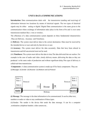
  • 1. Dr. Y. Narasimha Murthy Ph.D yayavaram@yahoo.com UNIT-I DATA COMMUNICATIONS Introduction: Data communications deals with the transmission (sending and receiving) of information between two locations by means of electrical signals. The two types of electrical signals may be either analog or digital. Digital Data communication is the name given to the communication where exchange of information takes place in the form of 0s and 1s over some transmission medium like a wire or wireless . The effectness of a data communication system depends on three fundamental characteristics .They are Delivery , Accuracy and Timeliness. (i) Delivery: The system must deliver data to the correct destination. Data must be received by the intended device or user and only by that device or user. (ii).Accuracy :The system must deliver the data accurately .Data that have been altered in transmission and left uncorrected must not be used. (iii).Timeliness: The system must deliver the data in time.The data delivered late are useless .For example in the case of audio and video ,timely delivery means ,delivering the data as they are produced in the same order of production and without significant delay.This type of delivery is called real-time transmission. Components : A data communication system is made up of five basic components .They are (i).Messages (ii).Sender (iii).Receiver (iv).Medium and (v).Protocol (i) Message: The message is the data information to be communicated. It can be either text, numbers or audio or video or any combination of these types. (ii).Sender: The sender is the device that sends the data message. It can be a computer ,workstation ,telephone handset ,video camera etc.. 1
  • 2. Dr. Y. Narasimha Murthy Ph.D yayavaram@yahoo.com (iii) Receiver : The receiver is the device that receives the messages. It can be a computer, workstation , telephone handset ,video camera or television etc. (iv).Medium:The transmission medium is the physical path by which a message travels from sender to receiver.It should be a twisted –pair wire ,co-axial cable,fiber optic cable or Radio waves etc. (v).Protocol: A protocol is a set of rules that govern the data communications.It represents an arrangement between the communicating devices.Without a protocol ,two devices may be connected but can not communicate. Basic terms and concepts : In data communication mainly the data is being transmitted between two devices namely transmitter and receiver. To understand this entire phenomena we need to know about five basic concepts .They are Line configuration Topology Transmission mode Categories of Networks. Internetworks. LINE CONFIGURATION: It refers to the way by which two or more communication devices are connected to a link.A link is a physical communication pathway that transfers data from one device to another. Based on the requirements, there are two possible line configurations.Point to point and multipoint • Point- to-point communication: A point to point connection provides a dedicated link between two devices.The total capacity of the link is used for the communication between these two devices. In most point-to point actual length of wire or cable is used to connect the two devices. For example the use of an infrared remote to change the channel in a Television establishes a point-to-point contact between remote and T.V 2
  • 3. Dr. Y. Narasimha Murthy Ph.D yayavaram@yahoo.com Similarly , in the case of voice communication using telephones, there is one calling party and one called party. Hence the communication is point-to-point. Multipoint : A multipoint or multi drop connection is one in which more than two specific devices share a single link. In a multi-point configuration the capacity of the channel is shared either spatially or temporally .If several devices are using the link simultaneously, they share it spatially on the other hand many users are using the same link by turn it is a time share connection.(means ,they share it temporally). • Broadcasting: In a broadcasting system, there is a central location from which information is sent to many recipients, as in the case of audio or video broadcasting. In a broadcasting system, the listeners are passive, and there is no reverse communication path. TOPOLOGY : The topology defines how the devices (computers, printers..etc) are connected and how the data flows from one device to another. There are two conventions while representing the topologies. The physical topology defines how the devices are physically wired. The logical topology defines how the data flows from one device to another. Topologies are broadly categorized into i) Bus ii ) Ring iii) Star iv) Mesh 3
  • 4. Dr. Y. Narasimha Murthy Ph.D yayavaram@yahoo.com Mesh Topology : In a mesh topology, every device has a dedicated point-to-point link to every other device. The term dedicated means that the link carries traffic only between the two devices it connects. To find the number of physical links in a fully connected mesh network with n nodes, we first consider that each node must be connected to every other node. Node 1 must be connected to n - I nodes, node 2 must be connected to n – 1 nodes, and finally node n must be connected to n - 1 nodes. We need n(n - 1) physical links. However, if each physical link allows communication in both directions (duplex mode), we can divide the number of links by 2. In other words, we can say that in a mesh topology, we need n(n -1) /2 duplex-mode links. A mesh offers several advantages over other network topologies. First, the use of dedicated links guarantees that each connection can carry its own data load, thus eliminating the traffic problems that can occur when links are shared by multiple devices. Second, a mesh topology is robust. If one link becomes unusable, it does not incapacitate the entire system. 4
  • 5. Dr. Y. Narasimha Murthy Ph.D yayavaram@yahoo.com Third, there is the advantage of privacy or security. When every message travels along a dedicated line, only the intended recipient sees it. Physical boundaries prevent other users from gaining access to messages. Finally, point-to-point links make fault identification and fault isolation easy. Traffic can be routed to avoid links with suspected problems. This facility enables the network manager to discover the precise location of the fault and aids in finding its cause and solution. The main disadvantages of a mesh are related to the amount of cabling and the number of I/O ports required. First, because every device must be connected to every other device, installation and reconnection are difficult. Second, the sheer bulk of the wiring can be greater than the available space (in walls, ceilings, or floors) can accommodate. Finally, the hardware required to connect each link (I/O ports and cable) can be prohibitively expensive. For these reasons a mesh topology is usually implemented in a limited fashion, for example, as a backbone connecting the main computers of a hybrid net work that can include several other topologies. One practical example of a mesh topology is the connection of telephone regional offices in which each regional office needs to be connected to every other regional office. Star Topology: In a star topology, each device has a dedicated point-to-point link only to a central controller, usually called a hub. The devices are not directly linked to one another. Unlike a mesh topology, a star topology does not allow direct traffic between devices. The controller acts as an exchange: If one device wants to send data to another, it sends the data to the controller, which then relays the data to the other connected device .A star topology is less expensive than a mesh topology. In a star, each device needs only one link and one I/O port to connect it to any number of others. This factor also makes it easy to install and reconfigure. Far less cabling needs to be housed, and additions, moves, and deletions involve only one connection: between that device and the hub. Other advantages include robustness. If one link fails, only that link is affected. All other links remain active. This factor also lends itself to easy fault identification and fault isolation. As long as the hub is working, it can be used to monitor link problems and bypass defective links. The main disadvantage of a star topology is the dependency of the whole topology on one single point, the hub. If the hub goes down, the whole system is dead. Although a star requires 5
  • 6. Dr. Y. Narasimha Murthy Ph.D yayavaram@yahoo.com far less cable than a mesh, each node must be linked to a central hub. For this reason, often more cabling is required in a star than in some other topologies (such as ring or bus).The star topology is used in local-area networks (LANs), Bus topology: In a bus topology all devices are connected to the transmission medium as backbone. There must be a terminator at each end of the bus to avoid signal reflections, which may distort the original signal. Signal is sent in both directions, but some buses are unidirectional. Good for small networks. Can be used for 10BASE5 (thick net), 10BASE2 (thin net) or 10BROAD36 (broad band) co-axial bus standards. Nodes are connected to the bus cable by drop lines and taps. A drop line is a connection running between the device and the main cable. A tap is a connector that either splices into the main cable or punctures the sheathing of a cable to create a contact with the metallic core. As a signal travels along the backbone, some of its energy is transformed into heat. Therefore, it becomes weaker and weaker as it travels farther and farther. For this reason there is a limit on the number of taps a bus can support and on the distance between those taps. Advantages of a bus topology include ease of installation. Backbone cable can be laid along the most efficient path, then connected to the nodes by drop lines of various lengths. In this way, a bus uses less cabling than mesh or star topologies. In a star, for example, four network devices in 6
  • 7. Dr. Y. Narasimha Murthy Ph.D yayavaram@yahoo.com the same room require four lengths of cable reaching all the way to the hub. In a bus, this redundancy is eliminated. Only the backbone cable stretches through the entire facility. Each drop line has to reach only as far as the nearest point on the backbone. Disadvantages of bus topology are difficulties in reconnection and fault isolation. A bus is usually designed to be optimally efficient at installation. It can therefore be difficult to add new devices. Signal reflection at the taps can cause degradation in quality. This degradation can be controlled by limiting the number and spacing of devices connected to a given length of cable. Adding new devices may therefore require modification or replacement of the backbone. The other disadvantage is , a fault or break in the bus cable stops all transmission, even between devices on the same side of the problem. The damaged area reflects signals back in the direction of origin, creating noise in both directions. Bus topology was the one of the first topologies used in the design of early local area networks. Ethernet LANs can use a bus topology, but they are less popular. Ring Topology : In a ring topology, each device has a dedicated point-to-point connection with only the two devices on either side of it. A signal is passed along the ring in one direction, from device to device, until it reaches its destination. Each device in the ring incorporates a repeater. When a device receives a signal intended for another device, its repeater regenerates the bits and passes them along. A ring is relatively easy to install and reconfigure. Each device is linked to only its immediate neighbors (either physically or logically). To add or delete a device requires changing only two connections. The only constraints are media and traffic considerations (maximum ring length and number of devices). In addition, fault isolation is simplified. Generally in a ring, a signal is circulating at all times. If one device does not receive a signal within a specified period, it can issue an alarm. The alarm alerts the network operator to the problem and its location. However, unidirectional traffic can be a disadvantage. In a simple ring, a break in the ring (such as a disabled station) can disable the entire network. This weakness can be solved by using a dual ring or a switch capable of closing off the break. 7
  • 8. Dr. Y. Narasimha Murthy Ph.D yayavaram@yahoo.com Ring topology was prevalent when IBM introduced its local-area network Token Ring. With the advent of higher-speed LANs this topology has become less useful. TRANSMISSION MODE :The term transmission mode is used to define the direction of signl flow between two linked devices.There are three types of transmission modes.They are Simplex , Half Duplex and Full-Duplex. Simplex: In simplex mode communication is unidirectional .i.e only one of the two devices on a link can transmit data and the other will only receive the data.As shown below a computer always sends the data and the monitor only receives the data. Similarly a key board always receives the data from the computer and computers send the data to the keyboard. Half Duplex: In half duplex both the devices can transmit and receive the data in the data communication. But not at the same time. When one device is sending the data the other will be receiving and vice versa. The use of a walkie-talkie by police and army personal is an example for this half-duplex transmission. The Half duplex method is like a one lane road with two directional traffic. While cars are travelling one direction , cars going the other direction must wait. In a half Duplex transmission the entire capacity of a channel is taken over by which ever of the two devices is transmitting at the time. Full Duplex : In full duplex mode (also called Duplex) both stations can transmit and receive data simultaneously. One common example is mobile phone or telephone line . 8
  • 9. Dr. Y. Narasimha Murthy Ph.D yayavaram@yahoo.com The full duplex mode is like a two way street with traffic following in both directions at the same time .In full duplex ,the signals going in either direction share the capacity of the link. This sharing can occur in two ways. Either the link must contain two physically separate transmission paths .One for sending and the other for receiving .or the capacity of the channel is divided between signals travelling in both directions. MODEMS: The term modem stands for Modulator & De-Modulator .The most familiar type of Data Communication Equipment (DTE) is a Modem. The term modem is a composite word that refers to the two functional entities that make up the device: a signal modulator and a signal demodulator. A modulator converts a digital signal into an analog signal using ASK, FSK, PSK, or QAM. A demodulator converts an analog signal into a digital signal. While a demodulator resembles an analog-to-digital converter, it is not in fact a converter of any kind. It does not sample a signal to create a digital facsimile; it merely reverses the process of modulation-that is, it performs demodulation. The modem consists of • Interface circuitry for linking with the host PC • Circuits to prepare data for transmission by adding the proper start, stop, and parity bits. • The modulator that converts PCs digital signals into analog signals. • The user interface that gives you commands of the modem's operation. 9
  • 10. Dr. Y. Narasimha Murthy Ph.D yayavaram@yahoo.com In the above diagram the two PCs are the DTEs i.e data Terminal Equipments. The Modems are DCEs. The demodulator takes theASK,FSK, PSK or QAM signal and decodes into a suitable form for a computer.It then relays the resulting digital signal to the receiving computer via the internet .Each DCE must be compatible with both its own DTE and other DTEs. Modem Standards The two modem standards are Bell modems and ITU· modems. Bell Modems The first commercial modems were produced by the Bell Telephone Company in early 1970s. As the first and, for a long time, lone manufacturer in the marketplace, Be defined the development of the technology and provided a de facto standard upon which subsequent manufacturers have built. Today there are dozens of companies producing hundreds of different types of modems worldwide. As complex and powerful as many models have become, they all evolved from the original and. relatively simple first models from Bell. The Bell 212 series modems have two speeds. The option of a second speed allows for compatibility with a wider number of systems. Both speeds operate in full-duplex mode over switched telephone lines. The slower speed, 300 bps, uses FSK The 201 series modems operate in either half-duplex mode over two-we switched lines or fullduplex mode over four-wire leased lines. The entire bandwidth over two-wire line is dedicated to a single direction of transmission. Four-wire lines allow for two completely separate channels, one in each direction, to be processed through single modem on each end. ITU-T Modem Standards Now a days most popular modems available are based on standards published by the ITU-T. These modems can be divided into two groups: those that are essentially equivalent to Bell series modems-for example, V.21 is similar to Bell modem 103-and those that are not. 10
  • 11. Dr. Y. Narasimha Murthy Ph.D yayavaram@yahoo.com Those ITU- T modems that are Bell series compatible are given below table with their Bell equivalents. ITU-T Bell Baud Rate Bit Rate Modulation V.21 103 300 300 FSK V.22 V.23 V.26 V.27 V.29 212 202 201 208 209 600 1200 1200 1600 2400 1200 1200 2400 4800 9600 4-PSK FSK 4-PSK 8-PSK 16-QAM Intelligent Modems Intelligent modems contain software to support a number of additional functions, such as automatic answering and dialing. Intelligent modems were first introduced by Hayes Microcomputer Products, Inc. More recently, other manufacturers have come out with Hayes compatible modems. Instructions in the Hayes and Hayes-compatible modems are called AT commands (AT is short for attention). 56K MODEMS : Traditional modems have a limitation on the data rate (maximum of 33.6 Kbps), However, new modems, with a bit rate of 56,000 bps, called 56K modems, are now on the market. These modems may be used only if one party is using digital signaling (such as through an Internet provider). They area symmetrical in that the downloading (flow of data from the Internet provider to the PC) is a maximum of 56 Kbps, while the uploading (flow of data from the PC to the Internet provider) can be a maximum of 33.6 Kbps. If one side is an Internet provider and the signal does not have to pass through a PCM converter, quantization is eliminated in one direction and the data rate can be increased to 56 Kbps . Encoding and Modulating : In the process of data communication the data must be transformed into signals to send them from one place to another. Data stored in a computer is in the form of 0s and 1s.To transform this data from one place to another place , it must be converted into digital signals.This is called Encoding digital data into digital signal or digital to digital conversion. The process of converting analog signal into digital signal is called analog to digital conversion or digitizing an analog signal. 11
  • 12. Dr. Y. Narasimha Murthy Ph.D yayavaram@yahoo.com The process of converting the digital signal into analog signal is called digital to analog conversion or modulating a digital signal. The process of sending an analog signal over long distances using a high frequency carrier signal is called analog to analog conversion or modulating an analog signal. Digital to Digital Encoding: It is the representation of a digital information by a digital signal .In this process of encoding the binary 1s and 0s generated by a computer are translated into a sequence of voltage pulses that can be transmitted over a cable or wire. This process is shown in the diagram below. There are three types of digital encodings. Unipolar ,Polar and Bi-polar. Uni-polar : Unipolar encoding uses only one level of value. i.e in a uni-polar scheme, all the signal levels are on one side of the time axis, either above or below. 12
  • 13. Dr. Y. Narasimha Murthy Ph.D yayavaram@yahoo.com The uni-polar encoding has two problems .One is DC component and the other is synchronization. Due to these limitations ,this encoding is not widely used. The DC component problem arises because the average amplitude of a uni-polar encoded signal is non- zero. This causes what is called a direct current component. When a signal contains a DC component, it cannot travel through the media that cannot handle DC components. The Synchronization problem in uni-polar encoding occur when ever the data stream includes a long uninterrupted series of 1s or 0s. Compared to polar encoding this scheme is very costly. Polar Schemes: In polar schemes, the voltages are on the both sides of the time axis. For example, the voltage level for 0 can be positive and the voltage level for I can be negative.The popular Polar encoding techniques are Non-return zero(NRZ),Return to Zero(RZ) and bi-phase. The bi-phase refers to two methods.One is Manchester used in Ethernet LAN and the second is Differential Manchester used by token rings LANs. Types of polar encodings is shown below. 13
  • 14. Dr. Y. Narasimha Murthy Ph.D yayavaram@yahoo.com Non-Return-to-Zero (NRZ) : In polar NRZ encoding, two levels of voltage amplitude are used. There are two versions of polar NRZ: NRZ-Land NRZ-I, as shown in Figure below. The figure also shows the value of r, the average baud rate, and the bandwidth. In the first variation, NRZ-L (NRZ-Level), the level of the voltage determines the value of the bit. In the second variation, NRZ-I (NRZ-Invert), the change or lack of change in the level of the voltage determines the value of the bit. If there is no change, the bit is 0; if there is a change, the bit is 1. NRZ-L and NRZ-J both have a DC component problem. The synchronization problem (sender and receiver clocks are not synchronized) also exists in both the schemes. This problem is more serious in NRZ-L than in NRZ-I. While a long sequence of datas can cause a problem in both schemes, a long sequence of 1s affects only NRZ-L. Another problem with NRZ-L occurs when there is a sudden change of polarity in the system. For example, if twisted-pair cable is the medium, a change in the polarity of the wire results in all 0s interpreted as I s and all I s interpreted 0s . NRZ-I does not have this problem. Both schemes have an average signal rate of N/2 Bd. Return to Zero (RZ) The main problem with NRZ encoding occurs when the sender and receiver clocks are not synchronized. The receiver does not know when one bit has ended and the next bit is starting. Hence the Return-to-zero (RZ) scheme is used. This scheme uses three values: positive, negative, and zero. In RZ, the signal changes not between bits but during the bit. In Figure below we see that the signal goes to 0 in the middle of each bit. It remains there until the beginning of the next bit. The main disadvantage of RZ encoding is that it requires two signal changes to encode a bit and therefore occupies greater bandwidth. This scheme has no DC component problem 14
  • 15. Dr. Y. Narasimha Murthy Ph.D yayavaram@yahoo.com . But the problem is the complexity : RZ uses three levels of voltage, which is more complex to create . As a result of all these deficiencies, the scheme is not used today. Instead, the betterperforming schemes like Manchester and differential Manchester schemes are used. Biphase: The best solution for the problem of synchronization is the Bi-phase encoding.This bi-phase encoding consists of two important encodings namely Manchester and Differential Manchester encodings . Manchester scheme is the resultant of the idea of RZ (transition at the middle of the bit) and the idea of NRZ-L . In Manchester encoding, the duration of the bit is divided into two halves. The voltage remains at one level during the first half and moves to the other level in the second half. The transition at the middle of the bit provides synchronization. On the other hand Differential Manchester, combines the ideas of RZ and NRZ-I. There is always a transition at the middle of the bit, but the bit values are determined at the beginning of the bit. If the next bit is 0, there is a transition; if the next bit is 1, there is none. Figure below shows both Manchester and differential Manchester encodings. 15
  • 16. Dr. Y. Narasimha Murthy Ph.D yayavaram@yahoo.com In Manchester and differential Manchester encoding, the transition at the middle of the bit is used for synchronization. The Manchester scheme overcomes several problems associated with NRZ-L, and differential Manchester overcomes several problems associated with NRZ-I. First, there is no baseline wandering. There is no DC component because each bit has a positive and negative voltage contribution. The only drawback is the signal rate. The signal rate for Manchester and differential Manchester is double that for NRZ. The reason is that there is always one transition at the middle of the bit and maybe one transition at the end of each bit. Manchester and differential Manchester schemes are also called bi-phase schemes. Channel capacity The maximum rate at which data can be transmitted over a communication channel under given conditions is referred as the channel capacity. Four important parameters are related in the evaluation of channel capacity. • Data rate: The rate at which data can be transmitted. Measured in bits per second • Bandwidth: The bandwidth of the transmitted signal. Measured in cycles per second (Hz). • Noise: The average level of unwanted signals over communication path. Expressed as the ratio between signal and noise. • Error rate: The rate at which error can occur. The Channel capacity (in cycles per second) is given by Shannon’s theorem. According to Shannon’s theorem C = B log2 (1+SNR) Where C is channel capacity in Cycles per second and this is error free capacity ; B is the bandwidth in Hertz and SNR = 10 log10 (Signal power/Noise power) known as signal to noise ratio. Here the SNR ratio assumes only white noise (thermal noise) where as other noise like impulse noise, attenuation noise and delay noise are not taken into account. Hence the actual value of channel capacity differs from the estimated value TRANSMISSION IMPAIRMENT: When signals travel through imperfect transmission media, the imperfection causes signal impairment. This means that the signal at the beginning of the medium is not the same as the 16
  • 17. Dr. Y. Narasimha Murthy Ph.D yayavaram@yahoo.com signal at the end of the medium. What is sent is not what is received. The impairment of signals is mainly caused due to attenuation, distortion, and noise in the medium. Attenuation Attenuation means a loss of energy. When a signal, simple or composite, travels through a medium, it loses some of its energy in overcoming the resistance of the medium. That is why a wire carrying electric signals gets warm . Some of the electrical energy in the signal is converted to heat. To compensate for this loss, amplifiers are used to amplify the signal. Distortion : Distortion means that the signal changes its form or shape. Distortion can occur in a composite signal made of different frequencies. Each signal component has its own propagation speed (see the next section) through a medium and, therefore, its own delay in arriving at the final destination. Differences in delay may create a difference in phase if the delay is not exactly the same as the period duration. In other words, signal components at the receiver have phases different from what they had at the sender. The shape of the composite signal is therefore not the same. Figure below shows the effect of distortion on a composite signal. 17
  • 18. Dr. Y. Narasimha Murthy Ph.D yayavaram@yahoo.com Noise Noise is another cause of impairment. Several types of noise, such as thermal noise, induced noise, crosstalk, and impulse noise, may corrupt the signal. Thermal noise is the random motion of electrons in a wire which creates an extra signal not originally sent by the transmitter. Induced noise comes from sources such as motors and appliances. These devices act as a sending antenna, and the transmission medium acts as the receiving antenna. Crosstalk is the effect of one wire on the other. One wire acts as ascending antenna and the other as the receiving antenna. Impulse noise is a spike (a signal with high energy in a very short time) that comes from power lines, lightning, and so on. Signal-to-Noise Ratio (SNR) The signal-to-noise ratio is defined as SNR = average signal power / average noise power. SNR is actually the ratio of what is wanted (signal) to what is not wanted (noise). A high SNR means the signal is less corrupted by noise; a low SNR means the signal is more corrupted by noise. Because SNR is the ratio of two powers, it is often described in decibel units SNR dB, defined as SNRdB = 10 log 10SNR. 18
  • 19. Dr. Y. Narasimha Murthy Ph.D yayavaram@yahoo.com Broadband System A "broadband" system has the capability for transmitting a broad range of analog frequencies over a single cable, Broadband LANs work in a similar way that cable television works. Broadband LANs transmit multiple radio frequency signals on the same cable, usually coaxial or sometimes fiber. This ability to send many types of communication simultaneously over the same cable, including voice, video, and data, distinguishes broadband LANs from the other common baseband LANs. For this operation, broadband LANs use the technique called frequency division multiplexing. Each channel in a broadband system is separated from the adjacent channel by a guard band, a frequency range over which no data will be transmitted. The simplest broadband LAN will be split into two channels, one for inbound data, one for outbound. Each of these gross channels may be split into two or many more channels. Broadband LANs use a tree-and-branch topology. The root of the tree is the head end, or central re- transmission facility. The trunk cable is attached to this root. Baseband System: Baseband methodology allows several devices to share a cable by means of a time-sharing technique. Each device is assigned a specific time slot some thousandths or millionths of a second in length in which to transmit. Only one device can transmit in a given time interval.This technique is called time division multiplexing. Baseband transmission is associated with specific network and performance characteristics. (a) Many types of media can be used, such as twisted pair, coaxial cable, and fiber optics. (b).There must be a protocol included in the network to assign time slots and provide access to the network. (c) . Modems are not required to connect devices to the cable when communicating digital information. (d).Any number of devices can be used for transmission or reception of information, without the addition of complex equipment, as long as there are enough slots available. Comparison Broadband (analog) transmission is generally regarded as a higher throughput technique because of the ability to simultaneously transmit multiple signals over a single cable. 19
  • 20. Dr. Y. Narasimha Murthy Ph.D yayavaram@yahoo.com Baseband is a highly efficient way of moving data from one piece of digital equipment to another. Hundreds of millions of data bits per second can move along the cable, with no slowdowns for analog conversion. These data bits, however, must move single file, and there is a finite limit to the total number of bits that can be transmitted during any given time period. The transmission rate advantage of broadband transmission is rapidly disappearing, however, with recent advances in digital technology, particularly in fiber optics, allowing digital baseband transmissions to rival, and even exceed broadband analog transmission speed. Baseband technology has benefitted substantially from continuing advances in integrated circuit technology. Installation, device connection, and control of communication traffic are all less expensive for digital networks than for analog networks. Broadband cable per foot is less expensive than baseband. The additional hardware needed (modems and directional couplers) to modulate the data signal for analog transmission from point to point and the more complex design engineering required will however raise the cost of installing broadband. MULTIPLEXING : Multiplexing is the techniques that allows the simultaneous transmission of multiple signals across a single data link .As data and telecommunications use increases, so does traffic. The figure below shows the basic format of a multiplexed system. The lines on the left direct their transmission streams to a multiplexer (MUX), which combines them into a single stream (many-to one).At the receiving end, that stream is fed into a de-multiplexer (DEMUX), which separates the stream back into its component transmissions (one-to-many) and directs them to their corresponding lines. In the figure, the word link refers to the physical path. The word channel refers to the portion of a link that carries a transmission between a given pair of lines. One link can have many (n) channels. There are three basic multiplexing techniques: frequency-division multiplexing, wavelengthdivision multiplexing, and time-division multiplexing. The first two techniques designed for analog signals, the third one is , for digital signals 20
  • 21. Dr. Y. Narasimha Murthy Ph.D yayavaram@yahoo.com Frequency-Division Multiplexing : Frequency-division multiplexing (FDM) is an analog technique that can be applied when the bandwidth of a link (in hertz) is greater than the combined bandwidths of the signals to be transmitted. In FDM, signals generated by each sending device modulate different carrier frequencies. These modulated signals are then combined into a single composite signal that can be transported by the link. Carrier frequencies are separated by sufficient bandwidth to accommodate the modulated signal. These bandwidth ranges are the channels through which the various signals travel. Channels can be separated by strips of unused bandwidth-guard bands-to prevent signals from overlapping. In addition, carrier frequencies must not interfere with the original data frequencies. A very common application of FDM is AM and FM radio broadcasting. Radio uses the air as the transmission medium. A special band from 530 to 1700 kHz is assigned to AM radio. All radio stations need to share this band. Each AM station needs 10kHz of bandwidth. Each station uses a different carrier frequency, which means it is shifting its signal and multiplexing. The signal that goes to the air is a combination of signals. A receiver receives all these signals, but filters (by tuning) only the one which is desired. Without multiplexing, only one AM station could broadcast to the common link, the air. The same concept is also used in FM broadcasting. But the , FM has a wider band of 88 to 108 MHz , because each station needs a bandwidth of 200 kHz. Another common use of FDM is in television broadcasting. Each TV channel has its own bandwidth of 6 MHz. The first generation of cellular telephones (still in operation) also uses FDM Wavelength-Division Multiplexing: Wavelength-division multiplexing (WDM) is designed to use the high-data-rate capability of fiber-optic cable. The optical fiber data rate is higher than the 21
  • 22. Dr. Y. Narasimha Murthy Ph.D yayavaram@yahoo.com data rate of metallic transmission cable. Using a fiber-optic cable for one single line will waste the available bandwidth. So, multiplexing is used which allows to combine several lines into one. WDM is conceptually the same as FDM, except that the multiplexing and de-multiplexing involve optical signals transmitted through fiber-optic channels. The idea is combining different signals of different frequencies. The difference is that the frequencies are very high .Figure below gives a conceptual view of a WDM multiplexer and de-multiplexer. Very narrow bands of light from different sources are combined to make a wider band of light. At the receiver, the signals are separated by the de-multiplexer. Although WDM technology is very complex, the basic idea is very simple. Multiple light sources are combined into one single light at the multiplexer and do the reverse at the de-multiplexer.A multiplexer can be made to combine several input beams of light, each containing a narrow band of frequencies, into one output beam of a wider band of frequencies. A de-multiplexer can be made to reverse the process. The application of WDM is the SONET network in which multiple optical fiber lines are multiplexed and de-multiplexed. A new method, called dense WDM (DWDM), can multiplex a very large number of channels by spacing channels very close to one another. It achieves a greater efficiency than ordinary WDM. 22
  • 23. Dr. Y. Narasimha Murthy Ph.D yayavaram@yahoo.com Demultiplexing Process : The de-multiplexer uses a series of filters to decompose the multiplexed signal into its constituent component signals. The individual signals are then passed to a demodulator that separates them from their carriers and passes them to the output lines. Error Detection and Correction : During the transmission of data from one point to other there is every possibility that the data may be corrupted and errors may occur. The data transfer through a Network must be always with acceptable accuracy. So, these data errors must be detected and corrected for a good data communication. Some applications can tolerate a small level of error. For example, random errorsin audio or video transmissions may be tolerable, but when we transfer text, we expect a very high level of accuracy. Types of Errors The errors in data communication are divided into two types.(i)Single Bit Errors and (ii) Burst errors. Single Bit Errors: Whenever bits flow from one point to another, they are subject to unpredictable changes due to interference. This interference can change the shape of the signal. In a single-bit error, a 0 is changed to a 1 or a 1 to a 0. The term single-bit error means that only 1 bit of a given data unit (such as a byte, character, or packet) is changed from 1 to 0 or from 0 to 1. The figure above shows the effect of a single-bit error on a data unit. To understand the impact of the change, imagine that each group of 8 bits is an ASCII character with a 0 bit added to the left. In the above figure 10.1,00000010 (ASCII STX) was sent, meaning start of text, but 00001010 (ASCII LF) was received, meaning line feed. Single-bit errors are the least likely type of error in serial data transmission. For example let us , imagine data sent at 1 Mbps. This means that each bit lasts only 1/1,000,000 s, or 1µs. For a single-bit error to occur, the noise must have a duration of only 1µs, which is very rare because noise normally lasts much longer than this. 23
  • 24. Dr. Y. Narasimha Murthy Ph.D yayavaram@yahoo.com Burst Error The term burst error means that 2 or more bits in the data unit have changed from 1 to 0 or from 0 to 1.Here a burst of data is being corrupted and not a single bit. In the figure below the effect of a burst error on a data unit is shown. In this case, 100010001000011 was sent, but 0101110101100011 was received. Note that a burst error does not necessarily mean that the errors occur in consecutive bits. The length of the burst is measured from the first corrupted bit to the last corrupted bit. Some bits in between may not have been corrupted. A burst error is more likely to occur than a single-bit error. The duration of noise is normally longer than the duration of 1 bit, which means that when noise affects data, it affects a set of bits. The number of bits affected depends on the data rate and duration of noise. For example, if we are sending data at I kbps, a noise of 11100 s can affect 10 bits; if we are sending data at 1 Mbps, the same noise can affect 10,000 bits. Redundancy: The important concept in detecting or correcting errors is redundancy. To be able to detect or correct errors, we need to send some extra bits with our data. These redundant bits are added by the sender and removed by the receiver. Their presence allows the receiver to detect or correct corrupted bits. The correction of errors is more difficult than the detection. In error detection, we are looking only to see if any error has occurred. The answer is a simple yes or no. We are not even interested in the number of errors. A single-bit error is the same for us as a burst error. In error 24
  • 25. Dr. Y. Narasimha Murthy Ph.D yayavaram@yahoo.com correction, we need to know the exact number of bits that are corrupted and more importantly, their location in the message. The number of the errors and the size of the message are important factors. If we need to correct one single error in an 8-bit data unit, we need to consider eight possible error locations; if we need to correct two errors in a data unit of the same size, we need to consider 28 possibilities. The difficulty of the receiver in finding 10 errors in a data unit of 1000 bits can be clearly understood from the above example. There are two main methods of error correction. Forward error correction is the process in which the receiver tries to guess the message by using redundant bits. This is possible, as we see later, if the number of errors is small. Correction by retransmission is a technique in which the receiver detects the occurrence of an error and asks the sender to resend the message. Resending is repeated until a message arrives that the receiver believes is error-free. Coding Redundancy is achieved through various coding schemes. The sender adds redundant bits through a process that creates a relationship between the redundant bits and the actual data bits. The receiver checks the relationships between the two sets of bits to detect or correct the errors. The ratio of redundant bits to the data bits and the robustness of the process are important factors in any coding scheme. Figure below shows the general idea of coding. We can divide coding schemes into two broad categories: block coding and convolution coding. Block Coding In block coding, the message is divided into blocks, each of k bits, called data words. And r redundant bits are added to each block to make the length n = k + r. The resulting n-bit blocks are called code words. With k bits, a combination of 2k data words are created ; with n bits, we can create a combination of 2n code words. Since n > k, the number of possible code words is larger than the number of possible data words.The block coding process is one-to-one ; the same data word is always encoded as the same code word. This means that 2n - 2k code words are not used which are invalid or illegal. 25
  • 26. Dr. Y. Narasimha Murthy Ph.D yayavaram@yahoo.com Error Detection : In block coding the receiver can detect a change in the original code word and the error can be detected if the following conditions are satisfied. The receiver has (or can find) a list of valid code words. The original codeword has changed to an invalid one. The sender creates code words out of data words by using a generator that applies the rules and procedures of encoding . Each codeword sent to the receiver may change during transmission. If the received codeword is the same as one of the valid code words, the word is accepted; the corresponding data word is extracted for use. If the received code word is not valid, it is discarded. However, if the codeword is corrupted during transmission but the received word still matches a valid codeword, the error remains undetected. This type of coding can detect only single errors. Two or more errors may remain undetected. Cyclic Redundancy Check (CRC): CRC is a category of error correction in data transmission using cyclic codes ,which is called the cyclic redundancy check (CRC) .This CRC is used in networks such as LANs and WANs. One of 26
  • 27. Dr. Y. Narasimha Murthy Ph.D yayavaram@yahoo.com the advantages of a cyclic code is that the encoder and decoder can easily and inexpensively implemented in hardware by using a handful of electronic devices. Also, a hardware implementation increases the rate of check bit and syndrome bit calculation. Reference: Data Communications and Networking, Second Edition ,by Behrouz A. Forouzan. 27