Hydromissions Ram Pump Schematic - Hawke's Bay Survival
•
2 j'aime•1,147 vues

Hydromissions Ram Pump Schematic - Hawke's Bay Survival

Recommandé
Recommandé
Contenu connexe
Tendances
Tendances (20)
Similaire à Hydromissions Ram Pump Schematic - Hawke's Bay Survival
Similaire à Hydromissions Ram Pump Schematic - Hawke's Bay Survival (20)
Plus de Fatin62c
Plus de Fatin62c (20)
Dernier
Dernier (20)
Hydromissions Ram Pump Schematic - Hawke's Bay Survival
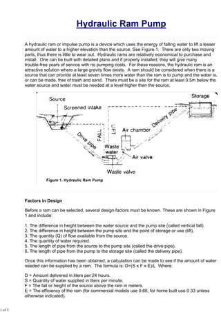
- 1. 1 of 5 Hydraulic Ram Pump A hydraulic ram or impulse pump is a device which uses the energy of falling water to lift a lesser amount of water to a higher elevation than the source. See Figure 1. There are only two moving parts, thus there is little to wear out. Hydraulic rams are relatively economical to purchase and install. One can be built with detailed plans and if properly installed, they will give many trouble-free years of service with no pumping costs. For these reasons, the hydraulic ram is an attractive solution where a large gravity flow exists. A ram should be considered when there is a source that can provide at least seven times more water than the ram is to pump and the water is, or can be made, free of trash and sand. There must be a site for the ram at least 0.5m below the water source and water must be needed at a level higher than the source. Factors in Design Before a ram can be selected, several design factors must be known. These are shown in Figure 1 and include: 1. The difference in height between the water source and the pump site (called vertical fall). 2. The difference in height between the pump site and the point of storage or use (lift). 3. The quantity (Q) of flow available from the source. 4. The quantity of water required. 5. The length of pipe from the source to the pump site (called the drive pipe). 6. The length of pipe from the pump to the storage site (called the delivery pipe). Once this information has been obtained, a calculation can be made to see if the amount of water needed can be supplied by a ram. The formula is: D=(S x F x E)/L Where: D = Amount delivered in liters per 24 hours. S = Quantity of water supplied in liters per minute. F = The fall or height of the source above the ram in meters. E = The efficiency of the ram (for commercial models use 0.66, for home built use 0.33 unless otherwise indicated).
- 2. 2 of 5 L = The lift height of the point of use above the ram in meters. Table 1 solves this formula for rams with efficiencies of 66 percent, a supply of 1 liter per minute, and with the working fall and lift shown in the table. For supplies greater than 1 liter/minute, simply multiply by the number of liters supplied. Table 1. Ram Performance Data for a Supply of 1 liter/minute Liters Delivered over 24 Hours Working Fall (m) Lift - Vertical Height to which Water is Raised Above the Ram (m) 5 7.5 10 15 20 30 40 50 60 80 100 125 1.0 144 77 65 33 29 19.5 12.5 1.5 135 96.5 70 54 36 19 15 2.0 220 156 105 79 53 33 25 19.5 12.5 2.5 280 200 125 100 66 40.5 32.5 24 15.5 12 3.0 260 180 130 87 65 51 40 27 17.5 12 3.5 215 150 100 75 60 46 31.5 20 14 4.0 255 173 115 86 69 53 36 23 16 5.0 310 236 155 118 94 71.5 50 36 23 6.0 282 185 140 112 93.5 64.5 47.5 34.5 7.0 216 163 130 109 82 60 48 8.0 187 149 125 94 69 55 9.0 212 168 140 105 84 62 10.0 245 187 156 117 93 69 12.0 295 225 187 140 113 83 14.0 265 218 167 132 97 16.0 250 187 150 110 18.0 280 210 169 124 20.0 237 188 140 Components of Hydraulic Ram A hydraulic ram installation consists of a supply, a drive pipe, the ram, a supply line and usually a storage tank. These are shown in Figure 1. Each of these component parts is discussed below: Supply. The intake must be designed to keep trash and sand out of the supply since these can plug up the ram. If the water is not naturally free of these materials, the intake should be screened or a settling basin provided. When the source is remote from the ram site, the supply line can be designed to conduct the water to a drive pipe as shown in Figure 2. The supply line, if needed, should be at least one pipe diameter larger than the drive pipe.
- 3. 3 of 5 Drive pipe. The drive pipe must be made of a non-flexible material for maximum efficiency. This is usually galvanized iron pipe, although other materials cased in concrete will work. In order to reduce head loss due to friction, the length of the pipe divided by the diameter of the pipe should be within the range of 150-1,000. Table 2 shows the minimum and maximum pipe lengths for various pipe sizes. Table 2. Range of Drive Pipe Lengths for Various Pipe Diameters Drive Pipe Size (mm) Length (meters) Minimum Maximum 13 2 13 20 3 20 25 4 25 30 4.5 30 40 6 40 50 7.5 50 80 12 80 100 15 100 The drive pipe diameter is usually chosen based on the size of the ram and the manufacturer's recommendations as shown in Table 3. The length is four to six times the vertical fall. Table 3. Drive Pipe Diameters by Hydram Manufacturer's Size Number Hydram Size 1 2 3 3.5 4 5 6 Pipe Size (mm) 32 38 51 63.5 76 101 127 Ram. Rams can be constructed using commercially available check valves or by fabricating check valves. They are also available as manufactured units in various sizes and pumping capacities. Rams can be used in tandem to pump water if one ram is not large enough to supply the need. Each ram must have its own drive pipe, but all can pump through a common delivery pipe as shown in Figure 3.
- 4. 4 of 5 In installing the ram, it is important that it be level, securely attached to an immovable base, preferably concrete, and that the waste-water be drained away. The pump can-not operate when submerged. Since the ram usually operates on a 24-hour basis the size can be determined for delivery over a 24-hour period. Table 4 shows hydraulic ram capacities for one manufacturer's Hydrams. Table 4. Hydram Capacity by Manufacturer's Size Number Size of Hydram 1 2 3 3.5 4 5X 6X 5Y 6Y Volume of Drive Water Needed (liters/min) 7-16 12-25 27-55 45-96 68-137 136-270 180-410 136-270 180-410 Maximum Lift (m) 150 150 120 120 120 105 105 105 Delivery Pipe. The delivery pipe can be of any material that can withstand the water pressure. The size of the line can be estimated using Table 5. Table 5. Sizing the Delivery Pipe Delivery Pipe Size (mm) Flow (liters/min) 30 6-36 40 37-60 50 61-90 80 91-234 100 235-360 Storage Tank. This is located at a level to provide water to the point of use. The size is based on the maximum demand per day. Sizing a Hydraulic Ram A small community consists of 10 homes with a total of 60 people. There is a spring l0m lower than the village which drains to a wash which is 15m below the spring. The spring produces 30,000 liters of water per day. There is a location for a ram on the bank of the wash. This site is 5m higher than the wash and 35m from the spring. A public standpost is planned for the village 200m from the ram site. The lift required to the top of the storage tank is 23m. The following are the steps in design. Identify the necessary design factors: 1. Vertical fall is 10m. 2. Lift is 23m to top of storage tank. 3. Quantity of flow available equals 30,000 liters per day divided by 11,440 minutes per day (30,000/11,440) = 20.8 liters per minute. 4. The quantity of water required assuming 40 liters per day per person as maximum use is 60 people x 40 liters per day = 2,400 liters per day. 2,400/1,440 = 1.66 liters per minute (use 2 liters per minute) 5. The length of the drive pipe is 35m. 6. The length of the delivery pipe is 200m.
- 5. 5 of 5 The above data can be used to size the system. Using Table 1, for a fall of 10m and a lift of 80m, 117 liters can be pumped a day for each liter per minute supplied. Since 2,400 liters per day is required, the number of liters per minute needed can be found by dividing 2,400 by 117: 2,400/117 = 20.5 liters per minute supply required. From item 3 above, the supply available is 20.8 liters per minute so the source is sufficient. Table 3 can now be used to select a ram size. The volume of driving water or supply needed is 20.5 liters per minute. From Table 4, a No. 2 Hydram requires from 12 to 25 liters per minute. A No. 2 Hydram can lift water to a maximum height of 250m according to Table 4. This will be adequate since the lift to the top of the storage tank is 23m. Thus, a No. 2 Hydram would be selected. Table 3 shows that for a No. 2 Hydram, the minimum drive pipe diameter is 38mm. Table 2 indicates that the minimum and maximum length for a 40mm pipe (the closest size to 38mm) is 6m-40m. Since the spring is 35m away, the length is all right. Table 5 can be used to select a delivery pipe 30mm in diameter which fits the supply needed, 20.5 liters per minute. This document is not copyrighted, so you are free to print and distribute it. However, we do request that any such re-distribution be on a non-commercial basis only. Kindly reference US AID, 1982 as the author.