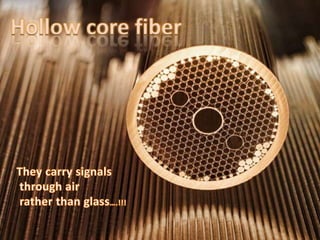
Hollow Core Fiber.
•Télécharger en tant que PPTX, PDF•
3 j'aime•2,104 vues

This presentation briefly explains working principle,advantages over optical fibers and current applications in real world.

Recommandé
Contenu connexe
Tendances
Tendances (20)
En vedette
En vedette (20)
Similaire à Hollow Core Fiber.
Similaire à Hollow Core Fiber. (20)
Dernier
Dernier (20)
Hollow Core Fiber.
- 2. OPTICAL FIBER :- •An optical fiber is a flexible, transparent fiber made by silica or plastic . •Optical fibers are used most often as a means to transmit light between the two ends of the fiber and find wide usage in fiber-optic communications, where they permit transmission over longer distances and at higher bandwidths (data rates) than wire cables. These Fibers are used because signals travel along them with lesser amounts of loss , fibers are also immune to electromagnetic interference .
- 3. • Optical fibers typically include a transparent core surrounded by a transparent cladding material with a lower index of refraction. • Light is kept in the core by the phenomenon of total internal reflection which causes the fiber to act as a waveguide. Fibers that support many propagation paths or transverse modes are called multi-mode fibers , while those that support a single mode are called single-mode fibers . • The field of applied science and engineering concerned with the design and application of optical fibers is known as fiber optics.
- 4. Advantages :- • Fibre optic cables have a much greater bandwidth than metal cables. The amount of information that can be transmitted per unit time of fibre over other transmission media is its most significant advantage. • An optical fibre offers low power loss. This allows for longer transmission distances. In comparison to copper; in a network, the longest recommended copper distance is 100m while with fibre, it is 2000m. • An optical fibre has greater tensile strength than copper or steel fibres of the same diameter. It is flexible, bends easily and resists most corrosive elements that attack copper cable. • Optical fibres are difficult to tap. As they do not radiate electromagnetic energy, emissions cannot be intercepted. • Fibre optic cables are much thinner and lighter than metal wires. They also occupy less space with cables of the same information capacity.
- 5. Why Do We Need HOLLOW CORE FIBER…..??
- 6. A hollow-core fiber is an optical fiber which guides light essentially within a hollow region, unhindered through air. The light beam is confined to the hollow core by the holes in the surrounding glass material, which looks like a honeycomb in cross section and creates a strictly no-go region for light, so that only a minor portion of the optical power propagates in the solid fiber material (typically a glass). According to the standard physical mechanism for guiding light in a fiber, this should not be possible: normally, the refractive index of the fiber core has to be higher than that of the surrounding cladding material, and there is no way of obtaining a refractive index of glass below that of air or vacuum, at least in the optical region.
- 7. How does it work….??
- 8. • A different guiding mechanism can be used, based on a photonic band gap, as can be realized in a photonic crystal fiber with a certain structure. Such fibers are also called Photonic Band Gap Fibers. The name air- guiding fibers is less precise, because it is actually not the air which provides the guidance. • The secret to hollow-core fiber is doing away with the cladding and replacing it with photonic crystals. The light shoots down the hollow core, and when it strikes the edge, the photonic crystals bounce the photons.
- 9. A photonic crystal is a periodic optical nanostructure that affects the motion of photons in much the same way that ionic lattices affect electrons in solids. Photonic crystals occur in nature in the form of structural coloration—and, in different forms, promise to be useful in a range of applications. Photonic crystals can, in principle, find uses wherever light must be manipulated. Photonic crystals are composed of periodic dielectric, metallo-dielectric—or even superconductor microstructures or nanostructures . Photons (behaving as waves) either propagate through this structure or not, depending on their wavelength.
- 10. • By doing away with the plastic or glass, these hollow-core fibers have lower signal loss ,allowing for longer distances between repeaters, and the increased speed of light ,about 30% faster. • The fact that each fiber is physically separated (single-spatial-mode) allows for higher bandwidth, and any polarization of the light is kept in tact .
- 11. Modes They can be used just like other single mode optical fibers Also, this single mode in hollow core fibers has quasi – Gaussian intensity distribution just as in the case of optical fibers Even though ,they can be used as single mode fibers till date there exists no such hollow core fiber in which light travels only in single mode i.e. It travels inside this fiber in multi – mode also In some cases , additional ‘surface’ modes also have been detected in these fibers But , the main drawback is that here too occurs higher loss of regarding this mode as compared to that in single mode These multi - modes decay very rapidly too
- 12. In particular , for a hole radius ρ = 0.47 λ for λ is hole spacing , the core supports a single mode and no surface modes for core radii between 0.8 λ and 1.1 λ
- 14. THE PARAMETERS ON WHICH FORMATION OF OPTICAL FIBER DEPENDS • The factors on which the formation of an Optical fiber depends is: • Dispersion • Attenuation
- 15. WHAT IS DISPERSION? • In optics, dispersion is the phenomenon in which the phase velocity of a wave depends on its frequency.[1] Media having this common property may be termed dispersive media. Sometimes the term chromatic dispersion is used for specificity. Although the term is used in the field of optics to describe light and other electromagnetic waves, dispersion in the same sense can apply to any sort of wave motion such as acoustic dispersion in the case of sound and seismic waves, in gravity waves (ocean waves), and for telecommunication signals propagating along transmission lines (such as coaxial cable) or optical fiber. • In optics, one important and familiar consequence of dispersion is the change in the angle of refraction of different colors of light,[2] as seen in the spectrum produced by a dispersive prism and in chromatic aberration of lenses. Design of compound achromatic lenses, in which chromatic aberration is largely cancelled, uses a quantification of a glass's dispersion given by its Abbe number V, where lowerAbbe numbers correspond to greater dispersion over the visible spectrum. In some applications such as telecommunications, the absolute phase of a wave is often not important but only the propagation of wave packets or "pulses"; in that case one is interested only in variations of group velocity with frequency, so-called group-velocity dispersion (GVD).
- 16. DISPERSION IN OPTICAL FIBERS. • As the optical pulses travel the length of the fiber, they are broadened or lengthened in time. This is called dispersion. Because the pulses eventually will become so out of step that they begin to overlap each other and corrupt the data, dispersion sets an upper limit on the data-carrying capabilities of a fiber.
- 17. TYPES OF DISPERSION. • There are three principal causes for this broadening of light: • Chromatic Dispersion – Different wavelengths travel at different velocities down the fiber. Because typical light sources provide power over a series or range of wavelengths, rather than from a single discrete spectral line, the pulses must spread out along the length of the fiber as they proceed. The high-speed lasers used in communications have very narrow spectral output specifications, greatly reducing the effect of chromatic dispersion.
- 18. • Modal Dispersion – Different fiber modes reflect at different angles as they proceed down the fiber. Because each modal angle produces a somewhat different path length for the beam, the higher-order modes reach the output end of the fiber behind the lower-order modes.
- 19. • Waveguide Dispersion – This minor cause for dispersion is due to the geometry of the fiber and results in different propagation velocities for each of the modes.
- 20. ATTENUATION. • Signals lose strength as they are propagated through the fiber; this is known as beam attenuation. Attenuation is measured in decibels (dB) with the relation:
- 21. • where Pin and Pout refer to the optical power going into and coming out of the fiber. The table below shows the power typically lost in a fiber for several values of attenuation in decibels. The attenuation of an optical fiber is wavelength dependent. At the extremes of the transmission curve, multiphoton absorption predominates. Attenuation is usually expressed in dB/km at a specific wavelength. Typical values range from 10 dB/km for step-index fibers at 850 nm to a few tenths of a dB/km for single- mode fibers at 1550 nm.
- 23. • There are several causes of attenuation in an optical fiber: • Rayleigh Scattering – Microscopic-scale variations in the index of refraction of the core material can cause considerable scatter in the beam, leading to substantial losses of optical power. Rayleigh scattering is wavelength dependent and is less significant at longer wavelengths. This is the most important loss mechanism in modern optical fibers, generally accounting for up to 90 percent of any loss that is experienced. • Absorption – Current manufacturing methods have reduced absorption caused by impurities (most notably water in the fiber) to very low levels. Within the bandpass of transmission of the fiber, absorption losses are insignificant. • Bending – Manufacturing methods can produce minute bends in the fiber geometry. Sometimes these bends will be great enough to cause the light within the core to hit the core/cladding interface at less than the critical angle so that light is lost into the cladding material. This also can occur when the fiber is bent in a tight radius (less than, say, a few centimeters). Bend sensitivity is usually expressed in terms of dB/km loss for a particular bend radius and wavelength.
- 24. Applications Some of the major application areas of optical fibers are: • Communications – Voice, data and video transmission are the most common uses of fiber optics, and these include: – Telecommunications – Local area networks (LANs) – Industrial control systems – Avionic systems – Military command, control and communications systems They can be useful in future for telecommunications
- 25. • Sensing – Fiber optics can be used to deliver light from a remote source to a detector to obtain pressure, temperature or spectral information. The fiber also can be used directly as a transducer to measure a number of environmental effects, such as strain, pressure, electrical resistance and pH. Environmental changes affect the light intensity, phase and/or polarization in ways that can be detected at the other end of the fiber. • Power Delivery – Optical fibers can deliver remarkably high levels of power for tasks such as laser cutting, welding, marking and drilling. • Illumination – A bundle of fibers gathered together with a light source at one end can illuminate areas that are difficult to reach – for example, inside the human body, in conjunction with an endoscope. Also, they can be used as a display sign or simply as
- 26. • Another application , perhaps closer to fruition , which can be successfully exploit these advantages offered by air-guiding PCFs , is the delivery of high-power continuous wave , nanosecond and sub-picosecond laser beams , which are useful for marking , machining and welding , laser – Doppler velocimetry ( deals with the measurement of parameters related to fluids ) , laser surgery and THz generation