

Recommandé
Contenu connexe
Tendances
Tendances (20)
En vedette
En vedette (20)
Similaire à 2011 maintaince of creastal bone
Similaire à 2011 maintaince of creastal bone (20)
Plus de Mohammed Alshehri
Plus de Mohammed Alshehri (20)
Dernier
Dernier (20)
2011 maintaince of creastal bone
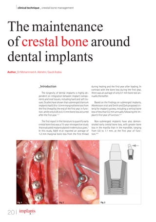
- 1. I clinical technique _ crestal bone management The maintenance of crestal bone around dental implants Author_Dr Mohammed A. Alshehri, Saudi Arabia _Introduction during healing and the first year after loading. In contrast with the bone loss during the first year, The longevity of dental implants is highly de- there was an average of only 0.1 mm bone lost an- pendent on integration between implant compo- nually thereafter. nents and oral tissues, including hard and soft tis- sues. Studies have shown that submerged titanium Based on the findings on submerged implants, implants had 0.9 to 1.6 mm marginal bone loss from Albrektsson et al. and Smith and Zarb proposed cri- the first thread by the end of the first year in func- teria for implant success, including a vertical bone tion, while only 0.05 to 0.13 mm bone loss occurred loss of less than 0.2 mm annually following the im- after the first year.1–3 plant’s first year of function.4, 5 The first report in the literature to quantify early Non-submerged implants have also demon- crestal bone loss was a 15-year retrospective study strated early crestal bone loss, with greater bone that evaluated implants placed in edentulous jaws.1 loss in the maxilla than in the mandible, ranging In this study, Adell et al. reported an average of from 0.6 to 1.1 mm, at the first year of func- 1.2 mm marginal bone loss from the first thread tion.6–8 Fig. 1 Fig. 2 Fig. 3 20 I implants 2_ 2011
- 2. clinical technique _ crestal bone management I _Surgical trauma detrimental temperature rise to 47°C or greater may be reached. The authors recommend that sur- Heat generated at the time of drilling, elevation of geons interrupt the drilling cycle every five to ten the periosteal flap and excessive pressure at the cre- seconds to allow irrigant time to cool the os- stal region during implant placement may contribute teotomy. to implant bone loss during the healing period. Periosteal flap Heat generation and excessive pressure The periosteal elevation has been suggested as Eriksson and Albrektsson reported that the crit- one of the possible contributing factors to crestal ical temperature for implant site preparation was implant bone loss. Wilderman et al. reported that 47°C for one minute or 40°C for seven minutes.9 the mean horizontal bone loss after osseous sur- Matthews and Hirsch demonstrated that tempera- gery with periosteal elevation is approximately ture elevation was influenced more by the force ap- 0.8 mm, and the reparative potential is highly de- plied than drill speed.10 When both drill speed and pendent upon the amount of cancellous bone (not applied force were increased, no significant in- cortical bone) underneath the cortical bone.13 The crease in temperature was observed owing to effi- bone loss at stage II implant surgery in successfully cient cutting.10, 11 osseointegrated implants is generally vertical and noted only around the implant characterised by Sharawy et al. compared the heat generated by saucerisation, not the surrounding bone even the drills of four different implant systems run at though during surgery all the bone was exposed. speeds of 1,225, 1,667 and 2,500 rpm.12 All of the Therefore, this hypothesis is not generally sup- drill systems were able to prepare an 8 mm site ported. without the temperature rising by more than 4°C (to 41°C). For all drill systems, the 1,225 rpm drill _Occlusal overload speed required a 30 to 40 % longer drilling time when compared with 2,500 rpm and a 20 to 40 % Research has indicated that occlusal overload reduction in the time required for bone tempera- often resulted in marginal bone loss or de-osseoin- ture to normalise. With greater depth of prepara- tegration of successfully osseointegrated im- Table I_Comparison between tooth tion and insufficient time between drill changes, a plants.1, 3, 14–20 The crestal bone around dental im- and implant. Tooth Implant Connection Periodontal ligament (PDL) Osseointegration (Brånemark et al., 1977), functional ankylosys (Schroeder et al., 1976) Proprioception Peridiontal mechanoreceptors Osseoperception Tactile sensitivity High Low (Mericske-Stern et al., 1995) Axial mobility 25–100 µm 3–5 µm (Sekine et al., 1986; Schulte, 1995) Movement phases Two phases One phase (Sekine et al., 1986) Primary: non-linear and complex Linear and elastic Secondary: linear and elastic Movement patterns Primary: immediate movement Gradual movement (Schulte, 1995) Secondary: gradual movement Fulcrum to lateral force Apical third of root (Parfitt, 1960) Crestal bone (Sekine et al., 1986) Load-bearing characteristics Shock absorbing function Stress concentration at crestal bone Stress distribution (Sekine et al., 1986) Signs of overloading PDL thickening, mobility, wear facets, Screw loosening or fracture, fremitus, pain abutment or prosthesis fracture, bonse loss, implant fracture (Zarb & Schmitt, 1990) Table I implants 2 _ 2011 I 21
- 3. I clinical technique _ crestal bone management plants could be a fulcrum for lever action when a Misch claimed that the stresses at the crestal bending moment is applied, suggesting that im- bone may cause microfracture or overload, result- plants could be more susceptible to crestal bone ing in early crestal bone loss during the first year loss by mechanical force. of function, and the change in bone strength from loading and mineralisation after one year al- Factors associated with increased bending over- ters the stress-strain relationship and reduces the load in dental implants: risk of microfracture during the following years.32 _Prostheses supported by one or two implants in Wiskott and Belser described a lack of osseointe- the posterior region (Rangert et al. 1995); gration attributed to increased pressure on the os- _Straight alignment of implants; seous bed during implant placement, establish- _Significant deviation of the implant axis from the ment of a physiological biological width, stress line of action; shielding and lack of adequate biomechanical in- _High crown/implant ratio; tegration between the load-bearing implant sur- _Excessive cantilever length (>15 mm in the face and the surrounding bone.33 They focused on mandible, Shackleton et al. 1994; >10–12 mm in the significance of the relationship between stress the maxilla, Rangert et al. 1989; Taylor 1991); and bone homeostasis. _Discrepancy in dimensions between the occlusal table and implant head; Based on a study by Frost,34 five types of strain _Para-functional habits, heavy bite force and ex- levels interrelated with different load levels in the cessive premature contacts (>180 µm in monkey bone were described: studies, Miyata et al. 2000; >100 µm in human 1) Disuse, bone resorption; studies, Falk et al. 1990); 2) Physiological load, bone homeostasis; _Steep cusp inclination; 3) Mild overload, bone mass increase; _Poor bone density/quality; and 4) Pathological overload, irreversible bone dam- _Inadequate number of implants. age; and 5) Fracture. The cortical bone is known to be least resistant to shear force, which is significantly increased by The concept of “microfracture” was proposed by bending overload. The greatest bone loss was seen Roberts et al., who concluded that crestal regions on the tension side.29 According to Von Recum, around dental implants are high-stress-bearing when two materials of different moduli of elastic- areas.35 They explained that if the crestal region is ity are placed together with no intervening material overloaded during bone remodelling, “cervical cra- and one is loaded, a stress contour increase is ob- tering” is created around dental implants. The served where the two materials first come into con- study recommended axially directed occlusion and tact.30 Photoelastic and 3-D finite element analysis progressive loading to prevent microfracture dur- studies demonstrated V- or U-shaped stress pat- ing the bone-remodelling periods. terns with greater magnitude near the point of the Table II_Studies regarding the first contact between implant and the photoelastic Progressive loading on dental implants during biologic width around natural teeth block, which is similar to the early crestal bone loss healing stages was first described by Misch in the or dental implants. phenomenon.31 1980s to decrease early implant bone loss and early Dental Implants Natural teeth Non-submerged Submerged Gargiulo et al. 57 Vacek et al. 58 Cochran Berglundh Abrahamsson 30 human skulls 10 human skulls et al. 68 et al. 53 et al. 71 Sulcus depth (SD) 0.69 mm 1.34 mm 0.16 mm 2.14 mm 2.14 mm Junctional epithelium (JE) 0.97 mm 1.14 mm 1.88 mm Connective tissue attachment (CT) 1.07 mm 0.77 mm 1.05 mm 1.66 mm 1.28 mm Biologic width 2.04 mm 1.91 mm 3.08 mm 3.80 mm 3.42 mm (JE + CT) (JE + CT) (SD + JE + CT) (SD + JE + CT) (SD + JE + CT) Table II 22 I implants 2_ 2011
- 4. AD implant failure. Based on the concept, progressive load- ing needs to be employed to allow the bone to form, re- model and mature to resist stress without detrimental bone loss by staging appli- cation of diet, occlusal con- tacts, prosthesis design and occlusal materials.36 Apple- ton et al. reported a decrease in crestal bone loss in pro- gressively loaded implants, compared with implants without progressive load- ing, within a similar healing and loading period. In addi- tion, digital radiographs indicated an increase in bone density in the crestal 40 % of the implant in the progressive loaded crowns.37 Greater crestal bone loss ob- served at the first year of function compared with following years can be explained by a reduced occlusal overload or increased resistance to occlusal overload after the first year of function including a functional adaptation of the oral muscula- ture, wear of the prosthesis material, and/or an increase in bone density after a cer- tain time period. _Peri-implantitis Peri-implantitis is one of the two main causative factors of implant failure in later stages. A correlation between plaque accumulation and progressive bone loss around implants has been reported in experimental studies and clinical studies. Tonetti and Schmid reported that peri-implant mucositis is a reversible inflamma- tory lesion confined to peri-implant mucosal tissues without bone loss. Peri-im- plantitis however begins with bone loss around dental implants.18 Clinical features of peri-implantitis were described by Mombelli as including ra- diographic evidence of vertical destruction of the crestal bone, formation of a peri- implant pocket in association with radiographic bone loss, bleeding after gentle probing, possibly with suppuration, mucosal swelling, redness and no pain typically.38 In an experimental study evaluating the pattern of ligature-induced breakdown of peri-implant and periodontal tissues in beagle dogs, significantly greater tissue de- struction was demonstrated clinically, radiographically, and histo-morphometrically at implant areas than at tooth sites. It was also found that significantly fewer vascu- lar structures existed at implant sites compared with periodontal tissues. The difference in collagen fibre direction (parallel to the implant surface and perpendicular to tooth surface) and amount of vascular structure may explain the faster pattern of tissue destruction in peri-implant tissues than periodontal tis- sues. Literature has shown that peri-implantitis is similar in nature to periodonti- tis in that the microbiota of peri-implantitis resemble the microbiota of periodon- titis; however, there has been no evidence that peri-implantitis induces crestal bone loss during healing and in the first year of function at a faster rate than fol- lowing years. Early crestal bone loss may result in an environment favourable for anaerobic bacterial growth, thus possibly contributing to more bone destruction in following years. In the majority of implants however the bone loss is dramatically reduced af- ter the first year of prosthesis loading. Therefore, peri-implantitis as the main causative factor for early implant bone loss may not be justified.
- 5. I clinical technique _ crestal bone management _Micro-gap and the platform-switch- and 1.07 mm is connective tissue attachment.46 ing concept These dimensions, however, are in no way static but subject to interindividual variation (from tooth to Many implant systems have an abutments used tooth and from patient to patient) and will also vary with conventional implant types that are flush with according to gingival type and implant concepts. the implant shoulder in the contact zone. This results in the formation of microcracks between the implant Numerous studies have shown that bone resorp- and the abutment. Numerous studies have shown tion around the implant neck does not start until the that bacterial contamination of the gap between the implant is uncovered and exposed to the oral cavity. implant and the abutment adversely affects the sta- This invariably leads to bacterial contamination of bility of the peri-implant tissue. If above-average ax- the gap between the implant and the superstruc- ial forces are exerted on the implant, a pumping ef- ture.47–50 Bone remodelling will progress until the bi- fect may ensue (depending on the positive inter- ological width has been created and stabilised. This nal/external connection at the interface), which may width progresses not only apically along the vertical then result in a flow of bacteria from the gap, caus- axis (Fig. 1), but also 1 to 1.5 mm horizontally, ac- ing the formation of inflammatory connective tissue cording to studies conducted by Tarnow et al. This is in the region of the implant neck.39–41 the reason for maintaining a minimum distance of 3 mm between two implants and platform switching Berglundh and Lindhe evaluated the micro-gap in the aesthetic reconstruction zone in order to of the Brånemark two-stage implant and found that obtain intact papillae and stable inter-implant inflamed connective tissue existed 0.5 mm above bone.51–53 and below the abutment–implant connection, which resulted in 0.5 mm bone loss within two weeks _Summary after the abutment had been connected to the im- plant.42 Ericsson et al. coined the term distance- Maintenance of crestal bone around dental im- sleeve-associated infiltrated connective tissue to plants is one of the critical factors that affect its describe this phenomenon. They interpreted this to longevity and aesthetic soft-tissue architecture. be a biological protective mechanism against the Preservation of such bone is a multifactorial process; bacteria residing in the microcrack, explaining the as summarised in this article some other factors re- plaque-independent bone loss of approximately lated to crestal bone loss have been investigated. 1mm during the first year. This bone loss may result These includes bone volume, bone quality, soft-tis- in a reduction of the marginal bone level in both the sue biotype, condition of the adjacent teeth, implant vertical and the horizontal dimensions.43 design, implant dimensions, abutment design, aug- mentation procedures, implant insertion depth, time If the microcrack is located close to the bone, the of loading, time of restoration, frequency of pros- creation of the biological width will occur at the ex- thetic secondary-component replacement, suturing pense of the bone. The platform-switching effect techniques and patient compliance. was first observed in the mid-1980s. At the time, larger-diameter implants were often restored with Proper tissue maintenance and care, regular hy- narrower abutments (Ankylos, DENTSPLY Friadent; gienic evaluations and patient education on proper AstraZeneca; Bicon), as congruent abutments were methods for home care are vital. Continued evalua- often still unavailable. As it later turned out, this was tion via probing, radiographic assessment and oral a remarkable coincidence.44 The platform-switching examination will allow the clinician to ensure long- concept requires that this micro-gap be placed away term maintenance and overall treatment success._ from the implant shoulder and closer toward the axis in order to increase the distance of this micro-gap Editorial note: A list of references is available from the from the bone as a protective measure. publisher. _Biological width _contact implants The clinical term biological width denotes the di- Dr Mohammed A. Alshehri mensions of periodontal and peri-implant soft-tis- Consultant Restorative and Implant Dentistry at the sue structures such as the gingival sulcus, the junc- Riyadh Military Hospital, Department of Dentistry tional epithelium, and the supra-crestal connective P.O. Box 225763 tissues.45 According to measurements conducted by Riyadh 11324, Saudi Arabia Gargiulo et al., the average biological width (from the base of the sulcus to the alveolar bone margin) is dr_mzs@hotmail.com 2.04 mm, of which 0.97 mm is epithelial attachment 24 I implants 2_ 2011