IEEE 802.3ba Ethernet 40-100 Gbps Standard Analysis
•
0 j'aime•222 vues

This document discusses the IEEE 802.3ba standard for Ethernet speeds of 40 Gbps and 100 Gbps. It describes the objectives of the standard to support speeds faster than 10 Gbps. The standard defines physical layer specifications for 40 Gbps and 100 Gbps transfer rates, including defining new Ethernet physical layer devices, sublayers, and interfaces to support these higher speeds.

Recommandé
Recommandé
Contenu connexe
Tendances
Tendances (19)
En vedette
Similaire à IEEE 802.3ba Ethernet 40-100 Gbps Standard Analysis
Similaire à IEEE 802.3ba Ethernet 40-100 Gbps Standard Analysis (20)
Dernier
Dernier (20)
IEEE 802.3ba Ethernet 40-100 Gbps Standard Analysis
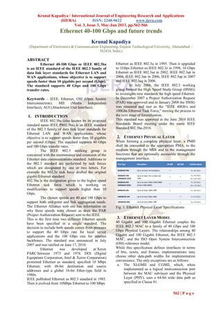
- 1. Krunal Kapadiya / International Journal of Engineering Research and Applications (IJERA) ISSN: 2248-9622 www.ijera.com Vol. 3, Issue 3, May-Jun 2013, pp.562-566 562 | P a g e Ethernet 40-100 Gbps and future trends Krunal Kapadiya (Department of Electronics & Communication Engineering, Gujarat Technological University, Ahmedabad – 382424, India,) ABSTRACT Ethernet 40-100 Gbps or IEEE 802.3ba is an IEEE standard of the IEEE 802.3 family of data link layer standards for Ethernet LAN and WAN applications, whose objective is to support speeds faster than 10 gigabits per second (Gbps). The standard supports 40 Gbps and 100 Gbps transfer rates. Keywords – IEEE, Ethernet, OSI (Open System Interconnection), MII (Media Independent Interface), AUI (Attachment Unit Interface). 1. INTRODUCTION IEEE 802.3ba (also known by its proposed standard name IEEE P802.3ba) is an IEEE standard of the 802.3 family of data link layer standards for Ethernet LAN and WAN applications, whose objective is to support speeds faster than 10 gigabits per second (Gbps). The standard supports 40 Gbps and 100 Gbps transfer rates. The IEEE 802.3 working group is concerned with the maintenance and extension of the Ethernet data communications standard. Additions to the 802.3 standard are performed by task forces which are designated by one or two letters. For example the 802.3z task force drafted the original gigabit Ethernet standard. 802.3ba is the designation given to the higher speed Ethernet task force which is working on modifications to support speeds higher than 10 Gbps. The chosen speeds are 40 and 100 Gbps to support both end-point and link aggregation needs. The Ethernet Alliance web site has information on why these speeds were chosen as does the PAR (Project Authorization Request) sent to the IEEE. This is the first time two different Ethernet speeds have been specified in a single standard. The decision to include both speeds comes from pressure to support the 40 Gbps rate for local server applications and the 100 Gbps rate for internet backbones. The standard was announced in July 2007 and was ratified on June 17, 2010. Ethernet was developed at Xerox PARC between 1973 and 1974. DIX (Digital Equipment Corporation, Intel & Xerox Corporation) promoted Ethernet as standard, specified 10 Mbps Ethernet, with 48-bit destination and source addresses and a global 16-bit Ether-type field in 1980s. IEEE published Ethernet as 802.3 standard in 1985. Then it evolved from 10Mbps Ethernet to 100 Mbps Ethernet as IEEE 802.3u in 1995. Then it upgraded to 1Gbps Ethernet as IEEE 802.3z in 1998, 10 Gbps Ethernet as IEEE 802.3ae in 2002, IEEE 802.3ak in 2004, IEEE 802.3an in 2006, IEEE 802.3ap in 2007 and IEEE 802.3aq in 2006. In July 2006, the IEEE 802.3 working group formed the High Speed Study Group (HSSG) to investigate new standards for high speed Ethernet. In December 2007 a Project Authorization Request (PAR) was approved and in January 2008 the HSSG was renamed and met as the "IEEE 40Gb/s and 100Gbs Ethernet Task Force," moving the process to the next stage of formalization. This standard was approved at the June 2010 IEEE Standards Board meeting under the name IEEE Standard 802.3ba-2010. 2. ETHERNET PHYSICAL LAYER When forming a complete physical layer, a PMD shall be connected to the appropriate PMA, to the medium through the MDI and to the management functions that are optionally accessible through the management interface. Fig. 1. Ethernet Physical Layer Specifications 3. ETHERNET LAYER MODEL 40 Gigabit and 100 Gigabit Ethernet couples the IEEE 802.3 MAC to a family of 40 Gbps and 100 Gbps Physical Layers. The relationships among 40 Gigabit and 100 Gigabit Ethernet, the IEEE 802.3 MAC, and the ISO Open System Interconnection (OSI) reference model. While this specification defines interfaces in terms of bits, octets, and frames, implementations may choose other data-path widths for implementation convenience. The only exceptions are as follows: a. The XLGMII and CGMII, which, when implemented as a logical interconnection port between the MAC sub-layer and the Physical Layer (PHY), uses a 64-bit wide data path as specified in Clause 81.
- 2. Krunal Kapadiya / International Journal of Engineering Research and Applications (IJERA) ISSN: 2248-9622 www.ijera.com Vol. 3, Issue 3, May-Jun 2013, pp.562-566 563 | P a g e b. The management interface, which, when physically implemented as the MDIO/MDC (Management Data Input/output and Management Data Clock) at an observable interconnection port, uses a bit-wide data path as specified in Clause 45. c. The PMA service interface, which, when physically implemented as XLAUI (40 Gigabit Attachment Unit Interface) at an observable interconnection port, uses a 4 lane data path as specified in Annex 83A or Annex 83B. The PMA service interface, which, when physically implemented as CAUI (100 Gigabit Attachment Unit Interface) at an observable interconnection port, uses a 10 lane data path as specified in Annex 83A or Annex 83B. d. The PMD service interface, which, when physically implemented as XLPPI (40 Gigabit Parallel Physical Interface) at an observable interconnection port, uses a 4 lane data path as specified in Annex 86A. The PMD service interface, which, when physically implemented as CPPI (100 Gigabit Parallel Physical Interface) at an observable interconnection port, uses a 10 lane data path as specified in Annex 86A. e. The MDIs as specified in Clause 84 for 40GBASE-KR4, in Clause 85 for 40GBASE- CR4, in Clause 86 for 40GBASE-SR4, Clause 87 for 40GBASE-LR4 and in Clause 88 for 100GBASE-LR4 and 100GBASE-ER4 all use a 4 lane data path. The MDIs as specified in Clause 85 for 100GBASE-CR10 and in Clause 86 for 100GBASE-SR10 use a 10 lane data path. Fig. 2. Ethernet Layer Model Physical Layer devices listed below are defined for operation at 40 Gbps and 100 Gbps. Fig. 3. Ethernet Physical Layers Devices 4. ETHERNET SUB-LAYERS Reconciliation Sub layer (RS) and Media Independent Interface: The Media Independent Interface (Clause 81) provides a logical interconnection between the MAC sub layer and Physical Layer entities (PHY). The Media Independent Interface is not intended to be physically instantiated; rather it can logically connect layers within a device. The XLGMII supports 40 Gbps and CGMII supports 100 Gbps operation through its 64- bit-wide transmit and receive data paths. The Reconciliation Sub layer (RS) provides a mapping between the signals provided at the
- 3. Krunal Kapadiya / International Journal of Engineering Research and Applications (IJERA) ISSN: 2248-9622 www.ijera.com Vol. 3, Issue 3, May-Jun 2013, pp.562-566 564 | P a g e Media Independent Interface (XLGMII and CGMII) and the MAC/PLS service definition. While XLGMII and CGMII are optional interfaces, they are used extensively in this standard as a basis for functional specification and provide a common service interface for the physical coding sub-layers defined in Clause 82. Physical Coding Sub-layer (PCS): The terms 40GBASE-R and 100GBASE-R refer to a specific family of Physical Layer implementations based upon the 64B/66B data coding method specified in Clause 82 and the PMA specification defined in Clause 83. The 40GBASE-R and 100GBASE-R PCSs perform encoding (decoding) of data from (to) the XLGMII/CGMII to 64B/66B code blocks, distribute the data to multiple lanes, and transfer the encoded data to the PMA. Forward Error Correction (FEC) sub-layer: The Forward Error Correction sub-layer is an optional sub-layer for 40GBASE-R and 100GBASE-R copper and backplane PHYs. The FEC sub-layer can be placed in between the PCS and PMA sub-layers or between two PMA sub-layers, is instantiated for each PCS lane, and operates autonomously on a per PCS lane basis. The FEC sub-layer is specified in Clause 74. Physical Medium Attachment (PMA) sub- layer: The PMA provides a medium-independent means for the PCS to support the use of a range of physical media. The 40GBASE-R and 100GBASE-R PMAs perform the mapping of transmit and receive data streams between the PCS and PMA via the PMA service interface, and the mapping and multiplexing of transmit and receive data streams between the PMA and PMD via the PMD service interface. In addition, the PMAs perform retiming of the received data stream when appropriate, optionally provide data loopback at the PMA or PMD service interface, and optionally provide test pattern generation and checking. The 40GBASE-R and 100GBASE-R PMAs are specified in Clause 83. Physical Medium Dependent (PMD) sub-layer: The Physical Medium Dependent sub-layer is responsible for interfacing to the transmission medium. The PMD is located just above the Medium Dependent Interface (MDI). The MDI, logically subsumed within each PMD sub-clause, is the actual medium attachment for the various supported media. The 40GBASE-R and 100GBASE-R PMDs and their corresponding media are specified in Clause 84 through Clause 88. Auto-Negotiation: Auto-Negotiation provides a linked device with the capability to detect the abilities (modes of operation) supported by the device at the other end of the link, determine common abilities, and configure for joint operation. Clause 73 Auto-Negotiation is used by the 40 Gbps backplane PHY (40GBASE-KR4, see Clause 84) and the 40 Gbps and 100 Gbps copper PHYs (40GBASE-CR4 and 100GBASE-CR10, see Clause 85). Management interface (MDIO/MDC): The optional MDIO/MDC management interface (Clause 45) provides an interconnection between MDIO Manageable Devices (MMDs) and Station Management (STA) entities. Management: Managed objects, attributes, and actions are defined for all 40 Gigabit and 100 Gigabit Ethernet components. Clause 30 consolidates all IEEE 802.3 management specifications so that 10/100/1000 Mbps, 10 Gbps, 40 Gbps, and 100 Gbps agents can be managed by existing network management stations with little or no modification to the agent code. 5. ARCHITECTURE 5.1. Ethernet 40 Gbps XLGMII (intra-chip) Logical, data/control, clock, no electrical specification 40GBASE-R PCS 64B/66B encoding Lane distribution and alignment Fig. 4. Ethernet 40 Gbps Architecture
- 4. Krunal Kapadiya / International Journal of Engineering Research and Applications (IJERA) ISSN: 2248-9622 www.ijera.com Vol. 3, Issue 3, May-Jun 2013, pp.562-566 565 | P a g e XLAUI (chip-to-chip or chip-to-module) 10.3125 GBaud electrical interface 4 lanes Physical instantiation of PMA service interface FEC service interface Abstract PMA service interface Abstract, can be physically instantiated as XLAUI electrical interface XLPPI (chip-to-module) 10.3125 GBaud electrical interface 4 lanes, optional for use with non retimed 40GBASE-SR4/LR4 optical PHY modules PMD service interface Logical 5.2. Ethernet 100 Gbps Fig. 5. Ethernet 100 Gbps Architecture CGMII(intra-chip) Logical, data/control, clock, no electrical specification 100GBASE-R PCS 64B/66B encoding Lane distribution and alignment CAUI(chip-to-chip or chip-to-module) 10.3125 GBaud electrical interface 10 lanes Physical instantiation of PMA service interface FEC service interface Abstract PMA service interface Abstract, can be physically instantiated as CAUI electrical interface CPPI (chip-to-module) 10.3125 GBaud electrical interface 10 lanes, for use with non retimed 100GBASE-SR10 optical modules PMD service interface Logical 100 GbE architecture diagram with CPPI CPPI3 is physical instantiation of PMD service interface for 100GBASE-SR10 PHYs Fig. 6. Ethernet 100 Gbps with CPPI Optional Compatibility Interfaces: 40 Gigabit Media Independent Interface (XLGMII): The XLGMII is designed to connect a 40 Gbps capable MAC to a 40 Gbps PHY. While conformance with implementation of this interface is not necessary to ensure communication, it allows flexibility in intermixing PHYs and DTEs at 40 Gbps speeds. The XLGMII is a logical interconnection intended for use as an intra- chip interface. 40 Gigabit Attachment Unit Interface (XLAUI): The XLAUI is a physical instantiation of the PMA service interface to extend the connection between 40 Gbps capable PMAs. While conformance with implementation of this interface is not necessary to ensure communication, it is recommended, since it allows maximum flexibility in intermixing PHYs and DTEs at
- 5. Krunal Kapadiya / International Journal of Engineering Research and Applications (IJERA) ISSN: 2248-9622 www.ijera.com Vol. 3, Issue 3, May-Jun 2013, pp.562-566 566 | P a g e 40 Gbps speeds. The XLAUI is intended for use as a chip-to-chip or a chip-to-module interface. 40 Gigabit Parallel Physical Interface (XLPPI): The XLPPI is provided as a physical instantiation of the PMD service interface for 40GBASE-SR4 and 40GBASE-LR4 PMDs. The XLPPI has four lanes. While conformance with implementation of this interface is not necessary to ensure communication, it allows flexibility in connecting the 40GBASE-SR4 or 40GBASE-LR4 PMDs. The XLPPI is intended for use as a chip-to-module interface. No mechanical connector is specified for use with the XLPPI. The XLPPI is optional. 100 Gigabit Media Independent Interface (CGMII): The CGMII is designed to connect a 100 Gbps capable MAC to a 100 Gbps PHY. While conformance with implementation of this interface is not necessary to ensure communication, it allows flexibility in intermixing PHYs and DTEs at 100 Gbps speeds. The CGMII is a logical interconnection intended for use as an intra-chip interface. 100 Gigabit Attachment Unit Interface (CAUI): The CAUI is a physical instantiation of the PMA service interface to extend the connection between 100 Gbps capable PMAs. While conformance with implementation of this interface is not necessary to ensure communication, it is recommended, since it allows maximum flexibility in intermixing PHYs and DTEs at 100 Gbps speeds. The CAUI is intended for use as a chip-to-chip or a chip-to-module interface. 100 Gigabit Parallel Physical Interface (CPPI): The CPPI is provided as a physical instantiation of the PMD service interface for 100GBASE-SR10 PMDs. The CPPI has ten lanes. While conformance with implementation of this interface is not necessary to ensure communication, it allows flexibility in connecting the 100GBASE-SR10 PMDs. The CPPI is intended for use as a chip- to-module interface. 6. ELECTRICAL INTERFACES Illustration of Inter-sub-layer interface and Medium dependent interface. XLAUI/CAUI and MDI have different electrical characteristics. Fig. 7. Electrical Interfaces of Ethernet 6.1. Ethernet 40 Gbps Fig. 8. Implementation of Ethernet 40 Gbps 6.2. Ethernet 100 Gbps Fig. 9. Implementation of Ethernet 100 Gbps 7. FUTURE STANDARDS IEEE P802.3bj 100 Gbps Backplane and Copper Cable Task Force. IEEE P802.3bg task force is developing a standard for 40 Gbps serial single mode fiber PMD. IEEE 802.3 Next Gen. 100 Gbps Optical Ethernet. 8. CONCLUSION 40 Gbps and 100 Gbps Ethernet use a common architecture. It addresses the needs of computing, network aggregation and core networking applications. The architecture is flexible and scalable to adapt current & future needs. It leverages existing 10 Gbps technology where possible. 9. ACKNOWLEDGMENTS I am grateful to Mr. Umesh Patel (Director – ASIC) and Mr. Manish Desai (Sr. Member Technical Staff) of Sibridge Technologies, Ahmedabad for providing guidelines and encouragement. I feel motivated and encouraged every time I attend their meeting. REFERENCES [1] IEEE Standard 802.3ba-2010, June 2010. [2] IEEE Standard 802.3-2008, December 2008. [3] Ilango Ganga, IEEE 802.3ba 40 and 100 Gigabit Ethernet Architecture, October 2010.