A Critique of the Proposed National Education Policy Reform
Mesuarement of the attenuatuion of the optical fiber ieee format
1. Measurement of Attenuation of the Optical Fiber
‘Abdulrahman Suratman1, Ong Sin Yee2, Nurul Shafikah Mohd Zain3, Mohamud Mire4
Radar Communication Laboratory, Faculty of Electrical Engineering
Universiti Teknologi Malaysia, 81310 Skudai, Johor, Malaysia
1abdurrahman3@live.utm.my
2ongsinyee@hotmail.com
3nshafikah91@yahoo.com
3mohamudmire@yahoo.com
Abstract— Attenuation varies depending on the fiber type and
the operating wavelength. There are several causes of optical loss
that will be investigate through this experiment. There are
including the length of the optical fiber, the losses between the
gap and the bending of the fiber. Using presenting method, in
which Module KL-95001 is used to run several test on the fiber
optic. Also, this method can be easily applied to measure the
attenuation and investigate the characteristic of the fiber optic.
Keywords— Characteristic optical fiber, attenuation factor of
optical fiber, attenuation of length, gap and bending of optical
fiber.
I. INTRODUCTION
The use and demand for optical fiber has grown
tremendously and optical-fiber applications are numerous.
These involve the transmission of voice, data, or video over
distances of less than a meter to hundreds of kilometers, using
one of a few standard fiber designs in one of several cable
designs. A fiber-optic cable is composed of two concentric
layers, called the core and the cladding. The core and cladding
have different refractive indices, with the core having a
refractive index of n1, and the cladding having a refractive
index of n2. The index of refraction is a way of measuring the
speed of light in a material. Light travels fastest in a vacuum.
The actual speed of light in a vacuum is 300,000 kilometers
per second, or 186,000 miles per second.
Attenuation is the reduction or loss of optical power as light
travels through an optical fiber. The longer the fiber is and the
farther the light has to travel, the more the optical signal is
attenuated. Consequently, attenuation is measured and
reported in decibels per kilometer (dB/km), also known as the
attenuation coefficient or attenuation rate.
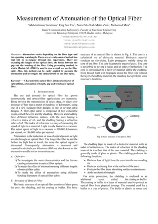
structure of an optical fiber is shown in Fig. 1. The core is a
cylindrical rod of dielectric material. Dielectric material
conducts no electricity. Light propagates mainly along the
core of the fiber. The core is generally made of glass. The core
is described as having a radius and an index of refraction. The
core is surrounded by a layer of material called the cladding.
Even though light will propagate along the fiber core without
the layer of cladding material, the cladding does perform some
necessary functions.
Fig. 1 Basic structure of an optical fiber
The cladding layer is made of a dielectric material with an
index of refraction n2. The index of refraction of the cladding
material is less than that of the core material. The cladding is
generally made of glass or plastic. The cladding performs the
following functions:
A. Objective
Reduces loss of light from the core into the surrounding
1) To investigate the main characteristics and the factors
air
causing attenuation in optical fiber system.
Reduces scattering loss at the surface of the core
2) To study the effect of attenuation using different lengths
Protects the fiber from absorbing surface contaminants
of optical fiber cable.
Adds mechanical strength
3) To study the effect of attenuation using different
bending diameters of optical fiber cable.
For extra protection, the cladding is enclosed in an
additional
layer
called
the coating or buffer.
B. Structure of Optical Fiber
The coating or buffer is a layer of material used to protect an
The basic structure of an optical fiber consists of three parts; optical fiber from physical damage. The material used for a
the core, the cladding, and the coating or buffer. The basic buffer is a type of plastic. The buffer is elastic in nature and
2. prevents abrasions. The buffer also prevents the optical fiber
from scattering losses caused by microbends. Microbends
occur when an optical fiber is placed on a rough and distorted
surface.
C. How Fiber Optics Works
Light travels down a fiber-optic cable by bouncing
repeatedly off the walls. Each tiny photon (particle of light)
bounces down the pipe .guided down the length of an optical
fiber. Now you might expect a beam of light, traveling in a
clear glass pipe, simply to leak out of the edges. But if light
hits glass at a really shallow angle (less than 42 degrees), it
reflects back in again as though the glass were really a mirror.
This phenomenon is called total internal reflection. It's one of
the things that keeps light inside the pipe as shown in Fig. 2.
making it suitable for long-distance
multichannel television broadcast systems.
telephony
and
1)Multimode Fiber: Multimode fiber, the first to be
manufactured and commercialized, simply refers to the fact
that numerous modes or light rays are carried simultaneously
through the waveguide. Modes result from the fact that light
will only propagate in the fiber core at discrete angles within
the cone of acceptance. This fiber type has a much larger core
diameter, compared to single-mode fiber, allowing for the
larger number of modes, and multimode fiber is easier to
couple than single-mode optical fiber. Multimode fiber may
be categorized as step-index or graded-index fiber. Multimode
Step-index Fiber Fig. 3 shows how the principle of total
internal reflection applies to multimode step-index fiber.
Because the core’s index of refraction is higher than the
cladding’s index of refraction, the light that enters at less than
the critical angle is guided along the fiber.
Fig. 2 How fiber optics works
Fig. 3 Total Internal Reflection in Multimode Step-index fiber
The other thing that keeps light in the pipe is the structure
of the cable, which is made up of two separate parts. The main
part of the cable in the middle is called the core and that's the
bit the light travels through. Wrapped around the outside of
the core is another layer of glass called the cladding. The
cladding's job is to keep the light signals inside the core. It can
do this because it is made of a different type of glass to the
core. The cladding has a higher refractive index than the core.
Light travels slower in the cladding than in the core. Any light
that tries to leak into the cladding tends to bend back inside
the core.
D. Core Characteristics
1) The diameter of the light carrying region of the fiber is
the "core diameter."
2) The larger the core, the more rays of light that travel in
the core.
3) The larger the core, the more optical power that can be
transmitted.
4) The core has a higher index of refraction than the
cladding.
5) The difference in the refractive index of the core and
the cladding is known as delta
E. Types of Optical Fiber
There are two basic types of fiber: multimode fiber optic
cable and single-mode fiber optic cable. Multimode fiber is
best designed for short transmission distances, and is suited
for use in LAN systems and video surveillance. Single-mode
fiber is best designed for longer transmission distances,
Multimode Graded-index Fiber Graded-index refers to the
fact that the refractive index of the core gradually decreases
farther from the center of the core. The increased refraction in
the center of the core slows the speed of some light rays,
allowing all the light rays to reach the receiving end at
approximately the same time, reducing dispersion. Fig. 4
shows the principle of multimode graded-index fiber.
Fig. 4 Multimode Graded-index Fiber
2)Single-mode Fiber: Single-mode fiber allows for a higher
capacity to transmit information because it can retain the
fidelity of each light pulse over longer distances, and it
exhibits no dispersion caused by multiple modes. Single-mode
fiber also enjoys lower fiber attenuation than multimode fiber.
Thus, more information can be transmitted per unit of time.
Like multimode fiber, early single-mode fiber was generally
characterized as step-index fiber meaning the refractive index
of the fiber core is a step above that of the cladding rather than
graduated as it is in graded-index fiber. Modern single-mode
fibers have evolved into more complex designs such as
matched clad, depressed clad and other exotic structures.
Single-mode fiber has disadvantages. The smaller core
diameter makes coupling light into the core more difficult.
The tolerances for single-mode connectors and splices are also
3. much more demanding. Single-mode fiber has gone through a
continuing evolution for several decades now.
Fig. 5 Single-mode Fiber
F. Advantages of Fiber Optic
1)Immunity to Electromagnetic Interference: Fiber optic
cables are immune to electromagnetic interference. It can also
be run in electrically noisy environments without concern as
electrical noise will not affect fiber. Electromagnetic
Interference is a common type of noise that originates with
one of the basic properties of electromagnetism. Magnetic
field lines generate an electrical current as they cut across
conductors. The flow of electrons in a conductor generates a
magnetic field that changes with the current flow.
Electromagnetic Interference does occur in coaxial cables,
since current does cut across the conductor. Fiber optics are
immune to this EMI since signals are transmitted as light
instead of current. Thus, they can carry signals through places
where EMI would block transmission.
2)Data Security: Magnetic fields and current induction
work in two ways. They don't just generate noise in signal
carrying conductors; they also let the information on the
conductor to be leaked out. Fluctuations in the induced
magnetic field outside a conductor carry the same information
as the current passing through the conductor. Optical fibers
are difficult to tap. As they do not radiate electromagnetic
energy, emissions cannot be intercepted. As physically
tapping the fiber takes great skill to do undetected, fiber is the
most secure medium available for carrying sensitive data.
3)Non Conductive Cables: Fiber optic cables can be made
non-conductive by avoiding metal in their design. These kinds
of cables are economical and standard for many indoor
applications. Outdoor versions are more expensive since they
require special strength members, but they can still be
valuable in eliminating ground loops and protecting electronic
equipment from surge damage.
4)Eliminating Spark Hazards: Because no electricity is
passed through optical fibers, there is no fire hazard. In some
cases, transmitting signals electrically can be extremely
dangerous. Most electric potentials create small sparks. The
sparks ordinarily pose no danger, but can be really bad in a
chemical plant or oil refinery where the air is contaminated
with potentially explosive vapours. One tiny spark can create
a big explosion. Potential spark hazards seriously hinder data
and communication in such facilities.
5)Ease of Installation: Fiber cables are easier to install
since they are smaller and more flexible. They can also run
along the same routes as electric cables without picking up
excessive noise. Increasing transmission capacity of wire
cables generally makes them thicker and more rigid. Such
thick cables can be difficult to install in existing buildings
where they must go through walls and cable ducts. Fiber optic
cables are much thinner and lighter than metal wires. They
also occupy less space with cables of the same information
capacity. Lighter weight makes fiber easier to install.
6)High Bandwidth over Long Distances: Fiber optic cables
have a much greater bandwidth than metal cables. The amount
of information that can be transmitted per unit time of fiber
over other transmission media is its most significant
advantage. Fiber optics have a large capacity to carry high
speed signals over longer distances without repeaters than
other types of cables. The information carrying capacity
increases with frequency. Generally, coaxial cables have a
bandwidth parameter of a few MHz/km, where else the fiber
optic cable has a bandwidth of 400MHz/km.
G. Attenuation
Attenuation is the reduction or loss of optical power as light
travels through an optical fiber. The longer the fiber is and the
farther the light has to travel, the more the optical signal is
attenuated. Consequently, attenuation is measured and
reported in decibels per kilometre (dB/km), also known as the
attenuation coefficient or attenuation rate.
Signal attenuation is defined as the ratio of optical input
power (Pi) to the optical output power (Po). Optical input
power is the power injected into the fiber from an optical
source. Optical output power is the power received at the fiber
end or optical detector. It can be expressed in dB:
The following equation defines signal attenuation as a unit of
length:
Attenuation varies depending on the fiber type and the
operating wavelength. For silica-based optical fibers, singlemode fibers have lower attenuation than multimode fibers.
The higher the wavelength, the lower the attenuation. Singlemode fibers usually operate in the 1310 nm or 1550 nm
regions, where attenuation is lowest. This makes single-mode
fibers the best choice for long distance communications.
Multimode fibers operate primarily at 850 nm and sometimes
at 1300 nm. Multimode fibers are designed for short distance
use; the higher attenuation at 850 nm is offset by the use of
more affordable optical sources.
H. Causes of Attenuation
Fiber attenuation is caused by scattering, absorption and
bending.
1)Absorption: Absorption is a major cause of signal loss in
an optical fiber. Absorption occurs when impurities, such as
metal particles or moisture, are trapped in the glass. These
cause attenuation at specific wavelengths by absorbing the
light at that wavelength and dissipating it in the form of heat
energy. Absorption is defined as the portion of attenuation
4. resulting from the conversion of optical power into another
energy form, such as heat.
Imperfections in the atomic structure induce absorption by
the presence of missing molecules or oxygen defects.
Absorption is also induced by the diffusion of hydrogen
molecules into the glass fiber. Since intrinsic and extrinsic
material properties are the main cause of absorption, they are
discussed further.
Intrinsic absorption is caused by basic fiber-material
properties. If an optical fiber were absolutely pure, with no
imperfections or impurities, then all absorption would be
intrinsic. Intrinsic absorption sets the minimal level of
absorption.
Extrinsic absorption is caused by impurities introduced into
the fiber material. Trace metal impurities, such as iron, nickel,
and chromium, are introduced into the fiber during fabrication.
Extrinsic absorption is caused by the electronic transition of
these metal ions from one energy level to another.
2)Scattering: Scattering losses are caused by the interaction
of light with density fluctuations within a fiber. Scattering
losses is the reflection of small amounts of light in all
directions as it travels down the fiber. Some of this light
escapes out of the core, while some travels back toward the
source. Some scattering is caused by miniscule variations in
the composition and density of the optical glass material itself;
this represents the theoretical lower limit of attenuation.
Additional variations in density and concentration - and
therefore, more scattering - are caused by the dopants used in
the core glass to change the refractive index of different types
of fiber. Fibers with increased dopant concentration exhibit
more scattering and greater attenuation than fibers with less
dopant in the core. That is why multimode fibers, with their
higher level of dopant in the core, have higher attenuation
than single-mode fibers.
During manufacturing, regions of higher and lower
molecular density areas, relative to the average density of the
fiber, are created. Light traveling through the fiber interacts
with the density areas as shown in Fig. 6. Light is then
partially scattered in all directions.
incidence decreases at the points with a too small curvature
radius and the condition of total reflection is not achieved
shown in Fig. 7. It is therefore necessary to maintain a
sufficiently large curvature radius of a fiber when installing
the cable nets. Bending loss is classified according to the bend
radius of curvature: microbend loss or macrobend loss.
Fig. 7 The losses caused by a bent fiber.
Microbends are small microscopic bends of the fiber axis
that occur mainly when a fiber is cabled. Macrobends are
bends having a large radius of curvature relative to the fiber
diameter. Microbend and macrobend losses are very important
loss mechanisms. Fiber loss caused by microbending can still
occur even if the fiber is cabled correctly. During installation,
if fibers are bent too sharply, macrobend losses will occur.
Microbend losses are caused by small discontinuities or
imperfections in the fiber. Uneven coating applications and
improper cabling procedures increase microbend loss.
External forces are also a source of microbends.
Macrobending occurs when a fiber is bent in a tight radius.
The bend curvature creates an angle that is too sharp for the
light to be reflected back into the core, and some of it escapes
through the fiber cladding, causing attenuation. This optical
power loss increases rapidly as the radius is decreased to an
inch or less. Fibers with a high numerical aperture and low
core/clad ratio are least susceptible to macrobend losses.
Microbends change the path that propagating modes take, as
shown in Fig. 8. Microbend loss increases attenuation because
low-order modes become coupled with high-order modes that
are naturally lossy.
Fig. 8 Microbend loss
Fig. 6 Light scattering
3)Bending Loss: When bending a fiber, the incidence
angles of beams at the boundary between the core and the
cladding of a fiber changes, consequently some beams get
emitted from the fiber. A bent fiber results in losses caused by
emittance and an increase in attenuation, because the angle of
Macrobend losses are observed when a fiber bend's radius
of curvature is large compared to the fiber diameter.
5. II. PROCEDURE
All of our experiments are conducted using optical fibers
with single mode characteristic.
A. List of Main Equipments
1) Module KL-95001 Fiber Optic Lab Equipment (Fig. 9)
2) Tektronix TDS 2014 Four Channel Digital Storage
Oscilloscope (Fig. 10)
3) Optical Fiber In Different Length of 1m, 3m, 5m, 10m
(Fig. 11)
Fig. 9 Module KL-95001
(CH1) input (red) and ground (black) was connected to
the output of signal generator.
3) The oscilloscope of channel 2 (CH2) input (red) and
ground (black) was connected to the Analog1 at the
Receiver output.
4) The DC power supply was connected to the power jack
of Module KL-95001 through the AC to DC Power
Adapter.
5) The signal Generator’s Frequency and Amplitude knobs
were set to have a 500Hz, 5Vp-p signal on the Analog
output. The Receiver Gain know was adjusted to low
level of gain.
6) The cinch nut of TX1 was loosened. One end of 1meter
optical fiber cable is inserted into the TX1 until the tip
of the fiber makes contact with the interior back wall of
the photo detector. Tightened thecinch. The other end
of optical fiber cable was inserted into RX1. The fiber
optic must in straight condition (Fig. 12).
7) The Vp-p value of Receiver Analog1 output was
measure from the oscilloscope CH2 and recorded in
Table 1. The total attenuation was calculated using
attenuation formula and recorded in Table 1.
𝑉𝑖
Attenuation = 20 log10 .
𝑉𝑜
8) Step 6 to 8 was repeated using different cable length of
3meter, 5meter (duplex) and 10meter (duplex) optical
fiber.
9) The graph of attenuation against optical fiber length
was plotted for 1meter, 3meter, 5meter (duplex) and
10meter (duplex) cable.
Fig. 10 Tektronix TDS 2014 Four Channel Digital Storage Oscilloscope
Fig. 11 Optical Fiber
Fig. 12 The fiber optic must in straight condition
B. Experiment 1: Attenuation due to Different Length of
Optical Fiber Cable.
Objective: 2) To study the effect of attenuation using
different lengths of optical fiber cable.
Equipment:
1) Module KL-95001
2) Optical fiber of length 1m, 3m, 5m and 10m
3) AC to DC power adapter
4) Oscilloscope
5) Connecting leads
Procedure:
1) The Module KL-95001 was used to set up the circuit
connections.
2) The Signal Generator Analogue output was connected
to the Transmitter input. The oscilloscope of channel 1
C. Experiment 2: Attenuation due to Different Gap of Optical
Fiber Cable.
Objective: 3) To study the effect of attenuation using
different gap of optical fiber cable.
Equipment:
1) Module KL-95001
2) Optical fiber of length 1m, 3m, 5m and 10m
3) AC to DC power adapter
4) Oscilloscope
5) Ruler
6) Connecting leads
Procedure:
1) The Module KL-95001 was used to set up the circuit
connections.
2) The Signal Generator Analogue output was connected
to the Transmitter input. The oscilloscope of channel 1
6. (CH1) input (red) and ground (black) was connected to
the output of signal generator.
3) The oscilloscope of channel 2 (CH2) input (red) and
ground (black) was connected to the Analog1 at the
Receiver output.
4) The DC power supply was connected to the power jack
of Module KL-95001 through the AC to DC Power
Adapter.
5) The signal Generator’s Frequency and Amplitude knobs
were set to have a 500Hz, 5Vp-p signal on the Analog
output. The Receiver Gain know was adjusted to low
level of gain.
6) The cinch nut of TX1 was loosened. One end of 1meter
optical fiber cable is inserted into the TX1 until the tip
of the fiber makes contact with the interior back wall of
the photo detector. Tightened thecinch. The end of
another 1meter optical fiber cable was inserted into
RX1. The fiber optic must in straight condition (Figure
12).
7) The cable gap width of both another ends of 1meter
optical fiber cable was measured by using ruler at 0mm
shown in Fig. 13.
8) The Vp-p value of Receiver Analog1 output was
measure from the oscilloscope CH2 and recorded in
Table 2. The total attenuation was calculated using
attenuation formula and recorded in Table 2.
𝑉𝑖
Attenuation = 20 log10 .
𝑉𝑜
9) Step 6 to 8 was repeated using different cable gap of
1mm, 2mm, 3mm and 4mm optical fiber.
10) Step 6 to 9 was repeated using different cable length of
3meter, 5meter (duplex) and 10meter (duplex) optical
fiber.
11) The graphs of total attenuation (TA) of gap against
optical fiber cable gap of 1meter, 3meter, 5meter
(duplex) and 10meter (duplex) cable length was plotted
on the same graph.
12) The attenuation of gap was calculated using attenuation
of gap formula and recorded in Table 3.
𝐴𝑡𝑡𝑒𝑛𝑢𝑎𝑡𝑖𝑜𝑛 (𝐴) 𝑜𝑓 𝑔𝑎𝑝
= 𝑇𝑜𝑡𝑎𝑙 𝐴𝑡𝑡𝑒𝑛𝑢𝑎𝑡𝑖𝑜𝑛 (𝑇𝐴) 𝑜𝑓 𝑔𝑎𝑝
−𝐴𝑡𝑡𝑒𝑛𝑢𝑎𝑡𝑖𝑜𝑛 𝑜𝑓 𝑓𝑖𝑏𝑒𝑟 𝑙𝑒𝑛𝑔𝑡ℎ
13) The graphs of attenuation (A) of gap against optical
fiber cable gap of 1meter, 3meter, 5meter (duplex) and
10meter (duplex) cable length was plotted on the same
graph.
Fig 13 Experiment attenuation of gap
D. Experiment 3: Attenuation due to Different Bendding of
Optical Fiber Cable
Objective: 3) To study the effect of attenuation using
different bending of optical fiber cable.
Equipment:
1. Module KL-95001
2. Optical fiber of length 1m, 3m, 5m and 10m
3. AC to DC power adapter
4. Oscilloscope
5. Ruler
6. Connecting leads
1) Procedure:
2) The Module KL-95001 was used to set up the circuit
connections.
3) The Signal Generator Analogue output was connected
to the Transmitter input. The oscilloscope of channel 1
(CH1) input (red) and ground (black) was connected to
the output of signal generator.
4) The oscilloscope of channel 2 (CH2) input (red) and
ground (black) was connected to the Analog1 at the
Receiver output.
5) The DC power supply was connected to the power jack
of Module KL-95001 through the AC to DC Power
Adapter.
6) The signal Generator’s Frequency and Amplitude knobs
were set to have a 500Hz, 5Vp-p signal on the Analog
output. The Receiver Gain know was adjusted to low
level of gain.
7) The cinch nut of TX1 was loosened. One end of 1meter
optical fiber cable is inserted into the TX1 until the tip
of the fiber makes contact with the interior back wall of
the photo detector. Tightened thecinch. The other end
of 1meter optical fiber cable was inserted into RX1.
The fiber optic must in straight condition (Figure 12).
8) The optical fiber cable was bent of 3 loop to have a
bend diameter of 10mm as shown in Figure 14.
9) The Vp-p value of Receiver Analog1 output was
measure from the oscilloscope CH2 and recorded in
Table 4. The total attenuation was calculated using
attenuation formula and recorded in Table 4.
𝑉𝑖
Attenuation = 20 log10 .
𝑉𝑜
10) Step 6 to 8 was repeated using different bending
diameter of 20mm, 30mm and 40mm optical fiber.
11) Step 6 to 9 was repeated using different cable length of
3meter, 5meter (duplex) and 10meter (duplex) optical
fiber.
12) The graphs of total attenuation (TA) of bending against
optical fiber bending diameter of 1meter, 3meter,
5meter (duplex) and 10meter (duplex) cable length was
plotted on the same graph.
13) The attenuation of gap was calculated using attenuation
of bending formula and recorded in Table 5.
𝐴𝑡𝑡𝑒𝑛𝑢𝑎𝑡𝑖𝑜𝑛(𝐴) 𝑜𝑓 𝑏𝑒𝑛𝑑𝑖𝑛𝑔
= 𝑇𝑜𝑡𝑎𝑙 𝐴𝑡𝑡𝑒𝑛𝑢𝑎𝑡𝑖𝑜𝑛(𝑇𝐴) 𝑜𝑓 𝑏𝑒𝑛𝑑𝑖𝑛𝑔
− 𝐴𝑡𝑡𝑒𝑛𝑢𝑎𝑡𝑖𝑜𝑛 𝑜𝑓 𝑓𝑖𝑏𝑒𝑟 𝑙𝑒𝑛𝑔𝑡ℎ
7. 14) The graphs of attenuation (A) of bending against
optical fiber bending diameter of 1meter, 3meter,
5meter (duplex) and 10meter (duplex) cable length was
plotted on the same graph.
3
4
0
1
2
3
4
0
1
2
3
4
5
10
25
A. Experiment 1: Attenuation due to Different Length of
Optical Fiber Cable
TABLE 1
THE ATTENUATION OF DIFFERENT LENGTH OF OPTICAL FIBER
Output Voltage
(Vpp)
2.6
2.2
1.8
1.2
Attenuation (dB)
Attenuation (dB)
III. RESULT
20
15
10
5
0
5.86
7.13
8.87
12.40
0
1
Attenuation (dB)
The Attenuation against Different Length of
Optical Fiber
15
5.86
8.87
Attenuation
of Fiber
Length (dB)
Optical Fiber Length (m)
3m
5m
10m
1
5.86
3
7.13
5
8.87
10
12.40
Graph 1 The Attenuation against Different Length of Optical Fiber
B. Experiment 2: Attenuation due to Different Gap of Optical
Fiber Cable
TABLE 2
THE TOTAL ATTENUATION (TA) OF DIFFERENT GAP OF OPTICAL FIBER
Fiber
Length
(m)
1
3
3m
5m
Cable
Gap
Width
(mm)
0
1m
Cable Gap
Width (mm)
0
1
2
3
4
0
1
2
Output
Voltage
(Vpp)
1.6
1.4
1.2
0.8
0.6
1.2
1.0
0.8
Total Attenuation
(TA) of Gap (dB)
9.90
11.06
12.40
15.92
18.42
12.40
13.98
15.92
4
10m
TABLE 3
THE ATTENUATION (A) OF DIFFERENT GAP OF OPTICAL FIBER
Optical
Fiber
Length
(m)
5
3
Graph 2 The Total Attenuation (TA) of Gap against Different Gap of Optical
Fiber
12.4
7.13
2
Cable Gap Width of Optical Fiber (mm)
1m
10
18.42
21.94
13.92
15.92
18.42
18.42
21.94
15.92
18.42
18.42
18.42
21.96
The Total Attenuation (TA) of Gap against
Different Gap of Optical Fiber
Fig. 14 Experiment attenuation of bending
Optical Fiber
Length (m)
1
3
5
10
0.6
0.4
1.0
0.8
0.6
0.6
0.4
0.8
0.6
0.6
0.6
0.4
0
1
2
3
4
0
1
2
3
4
0
1
2
3
4
0
1
2
3
4
Total
Attenuati
on (TA)
of Gap
(dB)
9.90
11.06
12.40
15.92
18.42
12.40
13.98
15.92
18.42
21.94
13.92
15.92
18.42
18.42
21.94
15.92
18.42
18.42
18.42
21.96
Attenuation
(A) of
Gap(dB)
-1.82
-0.66
0.68
4.2
6.7
-1.86
-0.28
1.66
4.16
7.68
-3.82
-1.82
0.68
0.68
4.2
-8.88
-6.38
-6.38
-6.38
-2.84
8. Graph 4 The Total Attenuation (TA) of Bending against Different Bending of
Optical Fiber
The Attenuation (A) of Gap against Different Gap
of Optical Fiber
Attenuation (dB)
𝐴𝑡𝑡𝑒𝑛𝑢𝑎𝑡𝑖𝑜𝑛(𝐴)𝑜𝑓 𝑔𝑎𝑝 = 𝑇𝑜𝑡𝑎𝑙 𝐴𝑡𝑡𝑒𝑛𝑢𝑎𝑡𝑖𝑜𝑛(𝑇𝐴) 𝑜𝑓 𝑔𝑎𝑝
− 𝐴𝑡𝑡𝑒𝑛𝑢𝑎𝑡𝑖𝑜𝑛 𝑑𝑢𝑒 𝑡𝑜 𝑓𝑖𝑏𝑒𝑟 𝑙𝑒𝑛𝑔𝑡ℎ
TABLE 5
THE ATTENUATION (A) OF DIFFERENT BENDING OF OPTICAL FIBER
Optical
Fiber
Length
(m)
10
5
0
-5
-10
0
1
2
3
3m
5m
1
5.86
3
7.13
5
8.87
10
12.40
4
Cable Gap Width of Optical Fiber (mm)
1m
Attenuati
on of
Fiber
Length
(dB)
10m
Graph 3 The Attenuation (A) of Gap against Different Gap of Optical Fiber
C. Experiment 3: Attenuation due to Different Bending of
Optical Fiber Cable
TABLE 4
THE TOTAL ATTENUATION (TA) OF DIFFERENT BENDING OF OPTICAL FIBER
Bending
Diameter
(mm)
Output
Voltage
(Vpp)
10
20
30
40
10
20
30
40
10
20
30
40
10
20
30
40
1.60
2.00
2.20
2.40
1.60
1.80
2.00
2.20
1.20
1.60
1.80
2.00
1.00
1.20
1.40
1.60
1
3
5
10
Total
Attenuation
(TA) of
Bending (dB)
9.90
7.96
7.13
6.38
9.90
8.87
8.00
7.13
12.4
9.90
8.87
8.00
13.98
12.39
11.06
9.90
The Total Attenuation (TA) of Bending against
Different Bending of Optical Fiber
Attenuation (dB)
15
10
20
30
40
10
20
30
40
10
20
30
40
10
20
30
40
Total
Attenuation
(TA) of
Bending
(dB)
9.90
7.96
7.13
6.38
9.90
8.87
8.00
7.13
12.4
9.90
8.87
8.00
13.98
12.39
11.06
9.90
Attenuation
(A) of
Bending
(dB)
-1.82
-3.76
-4.59
-5.34
-4.36
-5.39
-6.26
-7.13
-5.34
-7.84
-8.87
-9.74
-10.82
-12.41
-13.74
-14.9
𝐴𝑡𝑡𝑒𝑛𝑢𝑎𝑡𝑖𝑜𝑛(𝐴)𝑜𝑓 𝑏𝑒𝑛𝑑𝑖𝑛𝑔 = 𝑇𝑜𝑡𝑎𝑙 𝐴𝑡𝑡𝑒𝑛𝑢𝑎𝑡𝑖𝑜𝑛(𝑇𝐴) 𝑜𝑓 𝑏𝑒𝑛𝑑𝑖𝑛𝑔
− 𝐴𝑡𝑡𝑒𝑛𝑢𝑎𝑡𝑖𝑜𝑛 𝑑𝑢𝑒 𝑡𝑜 𝑓𝑖𝑏𝑒𝑟 𝑙𝑒𝑛𝑔𝑡ℎ
The Attenuation (A) of Bending against Different
Bending of Optical Fiber
0
10
Attenuation (dB)
Optical
Fiber
Length
(m)
Bending
Diameter
(mm)
20
30
40
-5
-10
-15
-20
Bending Diameter of Optical Fiber (mm)
1m
3m
5m
10m
Graph 5 The Attenuation (A) of Bending against Different Bending of Optical
Fiber
IV. DISCUSSION
10
5
0
10
20
30
40
Bending Radius of Optical Fiber (mm)
1m
3m
5m
10m
A. Experiment 1: Attenuation due to Different Length of
Optical Fiber Cable
This experiment was done to study the effect of attenuation
using different lengths of optical fiber cable. The result of
experiment using 1meter optical fiber cable shown that the
output voltage is lower than input voltage. This means it effect
will voltage gain at the receiver analog input. From our
experiment we were used lower gain and fixed the gain for all
experiment. The procedure for experiment 1 is repeated with
9. different lengths of 1meter, 3meter, 5meter (duplex) and
10meter (duplex) optical fiber cable.
In this experiment, as the length of the fiber optic increases,
the output voltage drops and the attenuation increases. This is
due to more power loss in the fiber optic over the length. This
power loss is due to scattering and absorption. Scattering
losses are caused by the interaction of light with density
fluctuations within a fiber. Scattering losses is the reflection of
small amounts of light in all directions as it travels down the
fiber. Some of this light escapes out of the core, while some
travels back toward the source. Absorption occurs when
impurities, such as metal particles or moisture, are trapped in
the glass. These cause attenuation at specific wavelengths by
absorbing the light at that wavelength and dissipating it in the
form of heat energy.
B. Experiment 2: Attenuation due to Different Gap of Optical
Fiber Cable
Gap loss is a type of signal strength loss that occurs in fiber
optic transmission when the signal is transferred from one
section of fiber or cable to another.
Specifically, gap loss happens when the signal from one
end of a piece of cable is transferred to another, but there is a
space, breakage, or gap between them. Since fiber optics
transmit data via light the light can cross this gap, but spreads
out and is weakened and diffused when it does so.
In this experiment, as the length of the gap increase, larger
amount of the transmitted power loss at the receiving core. As
a result of signal strength and cohesion being lost (due to the
scattering of the light), a fiber optic signal suffering from gap
loss is degraded in both quality and throughput.
C. Experiment 3: Attenuation due to Different Bending of
Optical Fiber Cable
In this experiment, as the radius for bending of the fiber
increase, the attenuation will decrease. When bending a fibre,
the incidence angles of beams at the boundary between the
core and the cladding of a fibre changes, consequently some
beams get emitted from the fibre. A bent fibre results in losses
caused by emittance and an increase in attenuation, because
the angle of incidence decreases at the points with a too small
curvature radius and the condition of total reflection is not
achieved. It is therefore necessary to maintain a sufficiently
large curvature radius of a fibre when installing the cable nets.
V. CONCLUSIONS
In conclusion, the objective of this report was met.
Experiments were carried out as you can see from the result
section. In this experiment, as the length and the gap of the
fiber optic increases, the output voltage drops and the
attenuation increases. As the radius for bending of the fiber
increase, the attenuation will decrease. The results obtained
were acceptable.
From our experiment, we use lower gain to our circuit at
the receiver. This will make the output voltage lower than
input voltage but it will make difficulties to get the reading of
output voltage. The reading is slightly different. To improve
the result we need to use higher gain so that we can get result
with better and can more clearly to compare the different.
ACKNOWLEDGMENT
We would like to express our deepest gratitude and
appreciation to our laboratory instructor Dr Yusri bin Md
Yunus for his excellent guidance, caring, patience,
suggestions and encouragement who helped usto coordinate
our project especially to design the link. We would also like to
acknowledge with much appreciation to all those who gave us
the possibility to complete this project. A special thanks goes
to the crucial role of the staff of the Optic Communication
Laboratory. Last but not least, again we would like to say
many thanks go to our laboratory instructor, Dr Yusri bin Md
Yunus who are given as full effort guiding in our team to
make the goal as well as the panels especially in our project
presentation that has improved our presentation skills by their
comment and tips.
REFERENCES
[1]
[2]
[3]
[4]
[5]
(2013, 5/11/2013). How Fiber Optic Work. Available:
http://computer.howstuffworks.com/fiber-optic1.htm
(2013, 5/11/2013). How Fiber Optic Communication System.
Available:
http://www.itblogs.in/communication/technology/fiberoptic-communication-sytem/
(2013, 5/11/2013). Attenuation of Optical Fiber. Available:
http://www.thefoa.org/tech/ref/testing/test/loss.html
(2013, 5/11/2013). halit eren. "optical loss." copyright 2000 crc press
llc <http://www.engnetbase.com>
(2013, 5/11/2013). Optical Fiber Loss and Attenuation. Available:
http://www.fiberoptics4sale.com/wordpress/optical-fiber-loss-andattenuation/