
Recommandé
Recommandé
Contenu connexe
Tendances
Tendances (20)
En vedette
En vedette (19)
Similaire à J0324056065
Similaire à J0324056065 (20)
Dernier
Dernier (20)
J0324056065
- 1. The International Journal Of Engineering And Science (IJES) ||Volume||3 ||Issue|| 2||Pages|| 56-65||2014|| ISSN(e): 2319 – 1813 ISSN(p): 2319 – 1805 An Experimental Study on Beam-Column Joints for Load Reversal 1 M. L. Anoop Kumar, 2Dr. S. Robert Ravi 1 Lecturer in Civil Engineering, S.V.Govt. Polytechnic, Dept. of Technical Education, Andhra Pradesh, India 2 Professor, Dept. of Civil Engg., Hindustan College of Engineering & Tech., Coimbatore, India --------------------------------------------------------ABSTRACT-------------------------------------------------------------Beam column joints in a reinforced concrete moment resisting frame are crucial zones for transfer of loads effectively between the connecting elements in the structure. The three main factors considered in design of beam column joint are Anchorage of main reinforcement of the beam, Confinement of the core of joint, Shear strength of the joint. In the present investigation, the beam column joint specimens were detailed as per IS 456:2000 and IS 13920:1993 and the influence of the increase of anchorage length by 25 % and 50 % for both the types of beam column joints was studied. Totally eighteen beam-column joint specimens were tested. Among the eighteen beam-column joint specimens nine specimens were designed and detailed according to IS 456:2000 specifications and the other nine specimens were designed according to IS 13920:1993 specifications. The results of the investigation proved that the load carrying capacity and the energy absorption capacity of the beam column joints were enhanced considerably by the increase of anchorage length in the joint specimens detailed as per IS 456:2000 and also IS 13920:1993. KEYWORDS – Beam column joint, Seismic loads, Load reversal. -------------------------------------------------------------------------------------------------------------------------------------------Date of Submission: 14 Februaty-2014 Date of Acceptance: 28 February-2014 -------------------------------------------------------------------------------------------------------------------------------------------- I. INTRODUCTION 1.1 General: In Reinforced Concrete buildings, portions of columns that are common to beams at their intersections are called beam-column joints. Since their constituent materials have limited strengths, the joints have limited force carrying capacity. When forces larger than these are applied during earthquakes, joints are severely damaged. Beam column joints in a reinforced concrete moment resisting frames are crucial zones for transfer of loads effectively between the connecting elements (i.e. beams and columns) in the structure. In normal design practice for gravity loads, the design check for joints is not critical and hence is not usually done. But, the failure of reinforced concrete frames during many earthquakes has demonstrated heavy distress due to shear in the joints that culminated in the collapse of the structure. Detailed studies of joints for buildings in seismic regions have been undertaken only in the past three to four decades. In reinforced concrete moment resisting framed structures, the functional requirement of a joint, which is the zone of intersection of beams and columns, is to enable the adjoining members to develop and sustain their ultimate capacity. The demand on this finite size element is always severe and more complex due to the possible two-way actions in three-dimensional framed structures. However, the codes consider one direction of loading at a time and arrive at the design parameters for the joint. 1.2 Design Requirements of Beam-column Joints: The basic requirement of design is that the joint must be stronger than the adjoining hinging members, usually the beams or columns. It is important to see that the joint size is adequate early in the design phase, otherwise the column or beam size may need to be changed to satisfy the joint strength or anchorage requirements. The design of beam column joints is predominantly focused on providing shear strength and adequate anchorage within the joint.Judicious detailing of reinforcement is of paramount importance to obtain a ductile response of reinforced concrete structures during a severe earthquake. One of the objectives of detailing is to ensure that the full strength of reinforcing bars, serving either as principal flexural or transverse www.theijes.com The IJES Page 56
- 2. An Experimental Study on Beam-Column Joints for Load Reversal reinforcement, can be developed under the most adverse condition that an earthquake may impose. Detailing features relevant to beam-column joints are concerned with aspects such as transverse reinforcement for shear strength and confinement, spacing of column longitudinal reinforcement and development length for embedded bars. The three main factors considered in design of joints are: 1. Anchorage of main reinforcement of the beam. 2. Confinement of the core of joint. 3. Shear strength of the joint. 1.3 Objectives: The objectives of the research work are: 1. To study the behavior of the beam-column joint, due to the variation of the anchorage length (Ld, 1.25Ld & 1.5Ld) under load reversal conditions. 2. To compare the beam-column joint designed as per IS456:2000 with that designed as per IS13920:1993 under load reversal conditions. 1.4 Need for the Study: Hui Yin et al (2001) conducted research on RC beam–column joints under reversed loading and reported degradation of the column shear strength was due to the bond deterioration of the beam bars across the joint panel. Saadatmanesh et al (1997) conducted a detailed investigation on the behavior of earthquake damaged reinforced concrete columns repaired with prefabricated FRP wraps and reported that the rate of stiffness degradation under large reversed cyclic loading was lower than that of corresponding original columns. Bajpai KK et al conducted experimental research on FRP wrapped Beam-column joints under cyclic loading and reported that the failure in joint was due to the premature shear failure of the joint region exhibiting performance of joint reinforcement. Stefano Pampanin et al conducted experimental research on Non-invasive retrofit of existing RC frames and reported that different damage or failure modes are expected to occur in beamcolumn joints depending on the typology (exterior or interior joint) and of the adopted structural details. Amorn Pimanmas et al (2007) conducted experiments on beam-column joint with and without bond between the beam bars and the joint core. It was found that the control specimen with full bonding fails by the crushing of a diagonal strut in the joint region. The failure is brittle. The cause of failure is due to lack of joint stirrups in the joint core. Sudhir K Jain et al (2004) reported that the behaviour and expected performance of flexural members of reinforced concrete moment resisting frames can be realised only when the joints are strong enough to sustain the severe forces set up under lateral loads. There has been less research conducted on the effect of anchorage length in the beam-column joint on the strength parameters. Hence, it was decided to carry out experimental investigations on the effect of anchorage length on beam-column joint II. METHODOLOGY 2.1 Overview: The investigation was mainly directed towards the study of behaviour of Reinforced Concrete beamcolumn joints due to increase in the anchorage length of the main bars of the beam into the column, the confinement of the joint portion as specified in IS 13920:1993 and the load deflection characteristics for load reversal conditions. The anchorage length was increased by 25 percent and 50 percent over those specified in IS 456:2000 and IS 13920:1993 and the specimens were tested for load reversal condition. 2.2 Test Specimen: The dimensions of the specimens were fixed to be 200x200mm in cross section and the height of the column portion was fixed as 1.5m and the length of the beam (cantilevered portion) was fixed as 0.6m. The grade of concrete proposed is M20 and the grade of steel used is Fe 415 for main reinforcement and Fe 250 for transverse reinforcement. www.theijes.com The IJES Page 57
- 3. An Experimental Study on Beam-Column Joints for Load Reversal The beam column joints specimens were designed and detailed as per IS 456:2000 and also as per IS 13920:1993.The experimental program consisted of testing eighteen beam-column joint specimens. Among the eighteen beam-column joint specimens nine specimens were designed and detailed according to IS 456:2000 specifications and the other nine specimens were designed according to IS 13920:1993 specifications.Among each set of 9 beam column joint specimens of each type mentioned above, three joint specimens were provided with an anchorage length Ld, other three were provided an anchorage length increased by 25 percent of L d i.e. 1.25 Ld and the remaining three specimens were provided with an anchorage length increased by 50 percent of Ld i.e. 1.5Ld than that specified in the respective codes. 2.3 Design details: The Beam Column joints are designed and detailed as per IS 456:2000 and also as per IS 13920:1993 specifications and the details of reinforcement are given in TABLE.1. The longitudinal reinforcement in the column portion in all the 18 specimens consisted of 4 no. 12mm Ø (HYSD) bars. The tension reinforcement in the beam portion consisted of 2 no 12mm Ø bars and the beam compression reinforcement consisted of 2 no. 12mm Ø bars. The main bars in the beam are extended beyond the column face into the beam column joint portion and it is anchored into the column portion. This portion of the main bars extended beyond the column face and anchored into the column is called anchorage length. The anchorage length of the tension and the compression reinforcement of the beam that is extended into the column was increased by 25 percent and 50 percent of that specified in the IS codes IS 456:2000 and IS 13920:1993 and the effect of increase in the anchorage length was investigated for load reversal condition. The details of the reinforcement adopted in the beam-column joint specimens both as per IS 456:2000 and IS 13920:1993 and the anchorage length details are given in TABLE.1 and TABLE.2 respectively and the reinforcement details are shown in Fig.1 and Fig.2. IS 13920: 1993 emphasizes the anchorage length and also on special confining reinforcement that is to be provided in the column portion. It reveals that the special confining reinforcement is to be provided over a length lo from each joint face, towards midspan, and on either side of any section, where flexural yielding may occur under the effect of earthquake forces. The length of special confining reinforcement to be provided shall not be less than (a) larger lateral dimension of the member at the section where yielding occurs, (b) 1/6 of clear span of the member, and (c) 450 mm. It also emphasizes on special confinement in beams. TABLE.1 Details of Reinforcement as per IS 456:2000 S.No 1 2 3 4 5 www.theijes.com Type of reinforcement Tension reinforcement in beam Compression reinforcement in beam Longitudinal reinforcement in column Stirrups in beams Lateral ties in columns The IJES Details 2 no 12mm Ø bars 2 no 12mm Ø bars 4 no 12mm Ø bars 6 mm ø bars at a spacing of 120mm c/c 6 mm ø bars at a spacing of 180mm c/c Page 58
- 4. An Experimental Study on Beam-Column Joints for Load Reversal TABLE.2 Details of Reinforcement as per IS 13920:1993 S.No 1 2 3 4 Type of reinforcement Tension reinforcement in beam Compression reinforcement in beam Longitudinal reinforcement in column Stirrups in beams 5 Lateral ties in columns 6 Special confinement in Beam Portion 7 Special confinement in Column portion Details 2 no 12 mm Ø bars 2 no 12 mm Ø bars 4 no 12 mm Ø bars 6 mm ø stirrups at a spacing of 80 mm c/c 6 mm ø stirrups at a spacing of 100 mm c/c 6 mm ø stirrups at a spacing of 40 mm c/c for a distance of 340 mm from face of joint 8 mm ø stirrups at a spacing of 50 mm c/c for a distance of 450mm on both sides of column from face of joint Fig.1 Reinforcement Details as per IS 456:2000 Fig.2 Reinforcement Details as per IS 13920:1993 www.theijes.com The IJES Page 59
- 5. An Experimental Study on Beam-Column Joints for Load Reversal 2.3.1 Anchorage Length: According to IS 456:2000, cl 26.2, the calculated tension or compression in any bar at any section shall be developed on each side of the section by an appropriate development length or end anchorage or by a combination. The development length Ld is given in cl 26.2.1 as: Ld =( øσs/4τbd) Where ø = nominal diameter of the bar, σs = stress in bar at the section considered at design load τbd = design bond stress given in cl 26.2.1.1 of IS 456:2000 The calculated Anchorage lengths as per IS 456:2000 are given in TABLE.3. This extra length of the main bars of the beam extended into the column portion to provide anchorage for bond stress development is called Anchorage Length. For the purpose of investigation, these anchorage lengths of bars in tension and in compression were increased by 25% and 50% than the actual calculated anchorage lengths were also given in TABLE.3. According to IS 13920:1993, clause 6.2.5, in an external joint, both the top and the bottom bars of the beam shall be provided with anchorage length, beyond the inner face of the column, equal to the development length in tension plus 10 times the bar diameter minus the allowance for 90 degree bend. In an internal joint, both face bars of the beam shall be taken continuously through the column. The calculated anchorage lengths as per IS 13920:1993 as well as the anchorage lengths increased by 25% and 50% than specified standard, used for the purpose of investigation are given in TABLE.4 In Fig.1 and Fig.2, the anchorage length of the beam reinforcement into the column portion is represented by Ld. TABLE.3 Anchorage Length as per IS 456:2000 Anchorage length(mm) Anchorage Length S.No Criteria Description Tension rod Compression rod 1 2 3 Normal Anchorage length Anchorage length increased by25 % Anchorage length increased by 50 % S.No 1 2 3 565 705 850 450 565 680 TABLE.4 Anchorage Length as per IS 13920:1993 Anchorage length Anchorage Length (mm) Criteria Description for Tension and Compression rods Normal Anchorage length 590 Anchorage length increased by25 % 735 Anchorage length increased by 50 % 880 2.4 Parameters and Considerations: In the present investigation, the influence of the increase of anchorage length by 25 % and 50 % for two types of beam column joints, i.e. those designed as per the IS 456:2000 and the other type designed as per IS 13920:1993 was studied. Generally, when the axial load on the column exceeds 50 to 60 % of its capacity, the axial load effect will be more predominant on the joint. In the case of the seismic forces, the effect of lateral load will be more predominant in the joint portion than the axial load. Hence, axial loads in excess of 50% of capacity of column may not truly reflect the performance of the joint under seismic load conditions. So, in the present investigation, the axial load in the column was limited to 20 to 30% of the capacity of the column which also helps to keep the beam-column joint specimen in position. www.theijes.com The IJES Page 60
- 6. An Experimental Study on Beam-Column Joints for Load Reversal 2.5 Test Programme: A test setup consisting of push-pull jack was set up horizontally as shown in Fig.3. A jack for applying the axial load was fitted to the test set up. Both the column ends were provided with hinged boundary conditions. At one of the column ends, a constant load of 20% to 30 % of the total axial i.e. 90kN to 135 kN load was applied by using a hydraulic jack of 500 kN capacity which has a load measuring arrangement fitted to it. A transverse load was applied at the free end of the beam by using a push pull jack at a distance of about 580mm from the column face. A deflectometer was placed on the other side of the beam which shows the deflection that occurs at the point of application of load on the beam. Fig.3 Test setup showing Beam column joint with required arrangements The testing involves pushing of the beam using the push pull jack by applying the load in the pushing direction. After applying considerable load in that direction, the pulling load was applied in the push pull jack until the beam was pulled by a considerable load even beyond the central position. Then the pushing load was applied until the beam comes back to its original position. So, one cycle of load reversal was applied to the test specimens. i.e. the beam was pushed from the normal position, then pulled to the normal position, then it was pulled back from the normal position and again pushed back towards the normal position. The deflectometer readings were noted down at particular load intervals and the deflection of the beam was determined. III. RESULTS AND DISCUSSION 3.1 Experimental Results: 3.1.1 Comparison of IS 456:2000 Test Specimens with anchorage length increased by 25 percent with those of normal anchorage length: A comparison of the test results of the beam column joint detailed as per IS IS456:2000 and the specimen with an increase in anchorage length of 25% were made. The load deflection curves are shown in Fig.4. IS 456:2000 Ld vs 1.25 Ld Load (kN) 20 10 Ld 0 -40 -30 -20 -10 0 10 20 1.25 Ld -10 -20 Deflection (mm) Fig.4 Load Deflection Curve For Specimens With Anchorage Length Ld and 1.25 Ld www.theijes.com The IJES Page 61
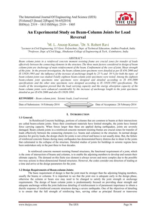
- 7. An Experimental Study on Beam-Column Joints for Load Reversal The comparative results indicate that when the anchorage length was increased by 25 percent than that specified in IS 456:2000 the load carrying capacity was increased by 20%, the deflection was reduced by 38% while pushing and deflection while pulling was reduced by 60.5 % and the energy absorption capacity was increased by 2.08%. 3.1.2 Comparison of IS 456:2000 Specimens with Anchorage Length Increased by 50 percent with those of Normal Anchorage Length: A comparison has been made between the test results of specimens detailed as per IS IS456:2000 and the specimens with anchorage length increased by 50%. The load deflection curves are shown in Fig.5. Fig. 5 Load Deflection Curve For Specimens With Anchorage Length Ld and 1.5 Ld The comparative results indicate that when the anchorage length was increased by 50 percent than that specified in IS 456:2000 load at first crack was increased by 15.6% and the load carrying capacity was increased by 20%. Though the deflection while pushing was not reduced much the deflection when pulling was reduced by 73% and the energy absorption capacity was increased by 20.27%. 3.1.3 Comparison of IS 13920:1993 Specimens with Normal Anchorage Length with those of IS 456:2000 Specimens with Normal Anchorage Length: A comparison of the beam column joint detailed as per IS 13920:1993 with normal anchorage length as with that detailed as per the IS 456:2000 with normal anchorage length is shown in Fig.6. load (kN) Ld of IS 456:2000 vs Ld of IS 13920:1993 -40 -20 20 15 10 5 0 -5 0 -10 -15 -20 Ld of IS 456:2000 20 Ld of IS 13920:1993 Deflection (mm0 Fig.6 Load Deflection Curve For Specimens With Anchorage Length Ld As Per IS 456:2000 With those of Ld as Per IS 13920:1993. The comparative results between the specimens cast as per IS 456:2000 with normal anchorage length and those cast as per IS 13920:1993 with normal anchorage length indicate that the load carrying capacity was increased by 16.67 %. Though the deflection while pushing was not reduced much the deflection when pulling was reduced by 76.58% and the energy absorption capacity was increased by 15.48%. www.theijes.com The IJES Page 62
- 8. An Experimental Study on Beam-Column Joints for Load Reversal 3.1.4 Comparison of IS 13920:1993 Specimens with Anchorage Length increased by 25 percent with those of IS 456:2000 Specimens with Normal Anchorage Length: A comparison of the beam column joint detailed as per IS 13920:1993 with anchorage length increased by 25% with that detailed as per the IS 456:2000 with normal anchorage length is made and the details are shown in Fig.7. Load (kN) Ld of IS456:2000 vs 1.25 Ld of IS 13920:1993 -40 -20 20 15 10 5 0 -5 0 -10 -15 -20 deflection (mm) 20 Ld 1.25 Ld of IS 13920 Fig.7 Load Deflection Curve For Specimens With Anchorage Length Ld As Per IS 456:2000 With those Of 1.25 Ld As Per IS 13920:1993. The comparative results between the specimens cast as per IS 456:2000 with normal anchorage length and those cast as per IS 13920:1993 with anchorage length increased by 25 % indicate that the load at first crack was increased by 8.89%, the load carrying capacity was increased by 20 %. Though the deflection while pushing was not reduced much the deflection when pulling was reduced by 62.4% and the energy absorption capacity was increased by 81.43%. 3.1.5 Comparison of IS 13920:1993 Specimens with Anchorage Length increased by 50 percent with those of IS 456:2000 Specimens with Normal Anchorage Length: A comparison of the beam column joint detailed as per IS 13920:1993 with anchorage length increased by 50% with that detailed as per the IS 456:2000 with normal anchorage length is given below. The load deflection curves are shown in Fig.8. Fig..8 Load Deflection Curve For Specimens With Anchorage Length Ld As Per IS 456:2000 With Those Of 1.5 Ld As Per IS 13920:1993. The comparative results between the specimens cast as per IS 456:2000 with normal anchorage length and those cast as per IS 13920:1993 with anchorage length increased by 50 % indicate that the load at first crack was increased by 17.33%, the load carrying capacity was increased by 46 %. The deflection while pushing was not reduced by 31.8% and the deflection while pulling was reduced by 75.6% and the energy absorption capacity was increased by 81.43%. www.theijes.com The IJES Page 63
- 9. An Experimental Study on Beam-Column Joints for Load Reversal 3.2 Summary of Test Results: The overall results obtained during the experimental investigation can be consolidated as follows. The load at first crack and Load carrying capacity for specimens detailed as per IS 456:2000 and those detailed as per IS 13920:1993 with varying anchorage lengths is shown in TABLE.5 AND TABLE.6 respectively. TABLE. 5 Load at First Crack in the Beam-Column Joint Specimens Criteria IS 456:2000 IS 13920:1993 Specimen type Ld 1.25Ld 1.5Ld Ld 1.25Ld 1.5Ld Load at First Crack(kN) 7.5 7.5 8.67 7.5 8.167 8.8 Increase in Load for first 15.6 % 8.89 % 17.33% crack with respect to Ld of IS 456:2000 Table.6 Load Carrying Capacity of Beam-Column Joint Specimens Criteria IS 456:2000 IS 13920:1993 Specimen type Ld 1.25Ld 1.5Ld Ld 1.25Ld 1.5Ld Ultimate Load (kN) 15 18 18 17.5 18 20 Increase in Load carrying 20% 20 % 16.67% 20 % 46% capacity with respect to Ld of IS 456:2000 The energy absorption capacity of the beam-column joint specimens detailed as per IS 456:2000 and those detailed as per IS 13920:1993 with varying anchorage lengths is shown in Table.7. Table.7 shows the increase in the energy absorption capacity with the increase of the anchorage length in the beam column joint specimens detailed as per IS 456:2000 and also in specimens detailed as per IS 13920:1993. The deflection of beam in the beam-column Joint specimens detailed as per IS 456:2000 and those detailed as per IS 13920:1993 with varying anchorage lengths is shown in Table.8 Table.7 Energy Absorption Capacity of the Beam-Column Joint Specimens Detailed as per code Specimen Criteria Energy Absorption % increase in Capacity Energy Absorption capacity IS 456:2000 Ld 227.9 IS 456:2000 1.25 Ld 232.66 2.08 IS 456:2000 1.5 Ld 274.1 20.27 IS 13920:1993 Ld 263.18 15.48 IS 13920:1993 1.25 Ld 413.49 81.43 IS 13920:1993 1.5 Ld 449.6 97.27 Table.8 Deflection of beam in the Beam-Column Joint specimens Criteria Specimen type Ld IS 456:2000 1.25Ld 1.5Ld Ld IS 13920:1993 1.25L 1.5Ld d Max Deflection while pushing(mm) Decrease in Deflection With respect to Ld of IS 456:2000 Maximum Deflection while pulling(mm) Decrease in Deflection With respect to Ld of IS 456:2000 www.theijes.com 13.7 8.4 14.87 12.8 15.6 9.34 - 38% - 7.03% - 37.8% 32.2 12.7 11 7.54 12.1 8.03 - 60.5% 65% 76.58% 62.4% 75.06% The IJES Page 64
- 10. An Experimental Study on Beam-Column Joints for Load Reversal IV. CONCLUSIONS In the case of specimens having details as per IS 456:2000, there is an increase of 20% in load carrying capacity when the anchorage length was increased by 25%.The increase in energy absorption capacity was found to be marginal. In the case of specimens having details as per IS 456:2000, there is an increase of 20% in both load carrying capacity and energy absorption capacity when the anchorage length was increased by 50%. In the case of specimens having details as per IS 13920:1993, there is only a marginal increase of 2.85% load carrying capacity when the anchorage length was increased by 25%. The increase in energy absorption capacity was found to be 57.11%. In the case of specimens having details as per IS 13920:1993, there is an increase of 14.28% in load carrying capacity when the anchorage length was increased by 50%. The increase in energy absorption capacity was found to be 70.83%. In the case of specimens having details as per IS 13920:1993 with normal anchorage length, there is 16.67% increase in load carrying capacity and 15.48% increase in energy absorption capacity than the specimens with details as per IS 456:2000 having normal anchorage length. In the case of specimens having details as per IS 13920:1993 with anchorage length increased by 25%, there is 20% increase in load carrying capacity and 81.43% increase in energy absorption capacity than the specimens with details as per IS 456:2000 having normal anchorage length. In the case of specimens having details as per IS 13920:1993 with anchorage length increased by 50%, there is an increase of 46% in load carrying capacity and 97.27% increase in energy absorption capacity than the specimens with details as per IS 456:2000 having normal anchorage length. In the case of specimens having details as per IS 13920:1993 with anchorage length increased by 25%, there is 77.7% increase in energy absorption capacity than the specimens with details as per IS 456:2000 having anchorage length increased by 25%. In the case of specimens having details as per IS 13920:1993 with anchorage length increased by 50%, there is 11.11% increase in load carrying capacity and 64% increase in energy absorption capacity than the specimens with details as per IS 456:2000 having anchorage length increased by 50%. It is found that the performance of joints is better when the anchorage length is increased by 50%. REFERENCES Journal Papers: [1] Hui Yin , Paulus Irawanl, Tso-Chien PanZ, and Chee Hiong Lim, “Behavior of Full-Scale Lightly Reinforced Concrete Interior Beam-Column Joints under Reversed Cyclic Loading”, Structural Engineering, Mechanics and Computation, Volume. 2., 2001 [2] Bajpai K.K.,. Murthy C.V. R., Durgesh Rai .C., “Influence of fiber wrap retrofitting on Gravity designed RC beam-column joints under cyclic loading” IIT Kanpur., 2000 [3] Antonopoulos C.P, Thanasis C. Triantafillou, “Analysis of FRP-Strengthened RC Beam-Column Joints”, Journal of composite for construction, Volume 7., 2002 [4] Antonopoulos, C. P., and Triantafillou, T. C. , „„Experimental investigation of FRP-strengthened RC beam-column joints.‟‟ Journal of Composite for Construction., 2003 [5] Stefano Pampanin, Constantin Christopolous, “Non-invasive retrofit of existing rc frames designed for gravity loads only”, fib 2003 Symposium 'Concrete Structures in Seismic Regions', paper n. 170., Athens, Greece., May 2003 [6] Teeraphot Supaviriyakit, Amorn Pimanmas, Thammasat, “Comparative Performance of a Substandard Beam-Column Joint with and Without Initial Bond Between Beam Bars and Concrete in the Joint Core”, Int. J. Sc. Tech., Vol. 12, No. 1, January-March 2007 [7] Pampanin. S., Calvi G.M., Moratti.M., “Seismic Behavior of R.C. Beam-Column Joints Designed for Gravity Only”., 12th European Conference on Earthquake Engineering, paper n.727, London 2002 Thesis: [8] Robert Ravi.S, “Studies on the behaviour of retrofitted reinforced concrete beam-column joint Using CFRP wrapping”., Karunya University, 2006 Books: [9] IS 456-2000 -Code of practice for plain & reinforced cement concrete, Bureau of Indian Standards, 2000 [10] IS 13920:1993- Ductile detailing of reinforced concrete structures subjected to seismic forces- Code of Practice, Bureau of Indian Standards, 2002 www.theijes.com The IJES Page 65