Km143 three axis pneumatic modern trailer operating with lever (wecompress)
•
0 j'aime•47 vues

Mechanical engineering project topics for final year, 1000KV Technologies, Live projects 1000kv technologies, EEE project list, mechatronics projects, live projects ameerpet, live projects near me, live projects institutes Hyderabad, mechanical projects hyderabad, 1000KV Technologies Live projects 9030844877, 9030844866 Educational consultant in Hyderabad, Telangana Address: #A2, Eureka court complex, 2nd floor, kallu compound road, 2nd floor, A2 flat, image hospital near, Ameerpet, Hyderabad, Telangana 500016

Recommandé
Recommandé
Contenu connexe
Tendances
Tendances (19)
Similaire à Km143 three axis pneumatic modern trailer operating with lever (wecompress)
Similaire à Km143 three axis pneumatic modern trailer operating with lever (wecompress) (20)
Plus de 1000kv technologies
Plus de 1000kv technologies (20)
Dernier
Dernier (20)
Km143 three axis pneumatic modern trailer operating with lever (wecompress)
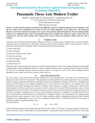
- 1. www.ijraset.com Volume 4 Issue V, May 2016 IC Value: 13.98 ISSN: 2321-9653 International Journal for Research in Applied Science & Engineering Technology (IJRASET) ©IJRASET: All Rights are Reserved 891 Pneumatic Three Axis Modern Trailer Bharth G1 , Sunil Kumar K 2 , Srinivasa Chari V3 , Lakshiminarayana T H4 1,2,3,4 Asst Prof, Department of Mechanical Engineering 1, 2, 4 RLJIT Doddaballapur Karnataka 3 MSEC Bangalore Karnataka Abstract— In this project has mainly concentrated on this difficulty, and hence a suitable arrangement has been designed. Such that the vehicles can be unloaded from the trailer in three axes without application of any impact force. By pressing the Direction control valve activated. The compressed air is goes to the pneumatic cylinder through valve. The ram of the pneumatic cylinder acts as a lifting the trailer cabin. The automobile engine drive is coupled to the compressor engine, so that it stores the compressed air when the vehicle running. This compressed air is used to activate the pneumatic cylinder, when the valve is activated. I. INTRODUCTION Automation can be achieved through computers, hydraulics, robotics, etc., of these sources, hydraulics form an attractive medium. Automation plays an important role in automobile. Nowadays almost all the automobile vehicle is being atomized in order to product the human being. The automobile vehicle is being atomized for the following reasons. To achieve high safety To reduce man power To increase the efficiency of the vehicle To reduce the work load To reduce the fatigue of workers To high responsibility Less Maintenance cost Pneumatic systems use pressurized gas, mostly air, to transmit motion and power. In fact, most concepts of hydraulic systems apply to the pneumatic systems including the Pascal’s law. Since a confined air behaves same as a confined fluid with respect to pressure, the force can be calculated using the pressure and area on which it is acting (i.e., F=p*A). Also, many components used in pneumatics, such as control valves, filters, actuators, motors, and so on. II. RELATED LITERATURES The word ‘pneuma’ comes from Greek and means breather wind. The word pneumatics is the study of air movement and its phenomena is derived from the word pneuma. Today pneumatics is mainly understood to means the application of air as a working medium in industry especially the driving and controlling of machines and equipment. Pneumatics has for some considerable time between used for carrying out the simplest mechanical tasks in more recent times has played a more important role in the development of pneumatic technology for automation. Pneumatic systems operate on a supply of compressed air which must be made available in sufficient quantity and at a pressure to suit the capacity of the system. When the pneumatic system is being adopted for the first time, however it wills indeed the necessary to deal with the question of compressed air supply.The key part of any facility for supply of compressed air is by means using reciprocating compressor. A compressor is a machine that takes in air, gas at a certain pressure and delivered the air at a high pressure. Compressor capacity is the actual quantity of air compressed and delivered and the volume expressed is that of the air at intake conditions namely at atmosphere pressure and normal ambient temperature. The compressibility of the air was first investigated by Robert Boyle in 1962 and that found that the product of pressure and volume of a particular quantity of gas. The usual written as PV = C (or) PıVı = P2V2 In this equation the pressure is the absolute pressured which for free is about 14.7 Psi and is of courage capable of maintaining a column of mercury, nearly 30 inches high in an ordinary barometer. Any gas can be used in pneumatic system but air is the mostly
- 2. www.ijraset.com Volume 4 Issue V, May 2016 IC Value: 13.98 ISSN: 2321-9653 International Journal for Research in Applied Science & Engineering Technology (IJRASET) ©IJRASET: All Rights are Reserved 892 used system now a day A. Selection Of Pneumatics Mechanization is broadly defined as the replacement of manual effort by mechanical power. Pneumatic is an attractive medium for low cost mechanization particularly for sequential (or) repetitive operations. Many factories and plants already have a compressed air system, which is capable of providing the power (or) energy requirements and the control system (although equally pneumatic control systems may be economic and can be advantageously applied to other forms of power). The main advantage of an all pneumatic system are usually economic and simplicity the latter reducing maintenance to a low level. It can also have outstanding advantages in terms of safety. B. Production Of Compressed Air Pneumatic systems operate on a supply of compressed air, which must be made available. In sufficient quantity and at a pressure to suit the capacity of the system. When pneumatic system is being adopted for the first time, however it wills indeed the necessary to deal with the question of compressed air supply. The key part of any facility for supply of compressed air is by means using reciprocating compressor. A compressor is a machine that takes in air, gas at a certain pressure and delivered the air at a high pressure. Compressor capacity is the actual quantity of air compressed and delivered and the volume expressed is that of the air at intake conditions namely at atmosphere pressure and normal ambient temperature. Clean condition of the suction air is one of the factors, which decides the life of a compressor. Warm and moist suction air will result in increased precipitation of condense from the compressed air. C. Reciprocating Compressors Built for either stationary (or) portable service the reciprocating compressor is by far the most common type. Reciprocating compressors lap be had is sizes from the smallest capacities to deliver more than 500 m³/min. In single stage compressor, the air pressure may be of 6 bar machines discharge of pressure is up to 15 bars. Discharge pressure in the range of 250 bars can be obtained with high pressure reciprocating compressors that of three & four stages. Single stage and 1200 stage models are particularly suitable for pneumatic applications , with preference going to the two stage design as soon as the discharge pressure exceeds 6 bar , because it in capable of matching the performance of single stage machine at lower costs per driving powers in the range . D. Choice of materials The material selected must possess the necessary properties for the proposed application. The various requirements to be satisfied can be weight, surface finish, rigidity, ability to withstand environmental attack from chemicals, service life, reliability etc. III. COMPONENTS AND DESCRIPTION A. Air Compressor The main function of the air compressor is to compress the air up to the required pressure. The maximum capacity of the compressor is 10 105 to 12 105 N/m2. This is a two stages or two-cylinder reciprocating air compressor. The two cylinders are for low and high compression. The air pressure is measured at various places by the use of pressure gauges. V-belt and pulley are used to drive the compressor. B. Pneumatic valves The pneumatic cylinder is regulated and controlled by pneumatic valves. These valves are actuated manually, mechanically, electrically, pneumatically, and by various combined mode of actuation. Need of Valves. C. Solenoid valve A solenoid is an electrical mechanical device that can convert electrical power to mechanical force and motion. It consists mainly of plunger, mostly a T type plunger, wire or coil and a C-frame. The working principle is such that when an electric current is passed through a coiled wire, a magnetic field sets up around the wire. Because of coiled wire, the magnetic field would be several times stronger around and through its centre.
- 3. www.ijraset.com Volume 4 Issue V, May 2016 IC Value: 13.98 ISSN: 2321-9653 International Journal for Research in Applied Science & Engineering Technology (IJRASET) ©IJRASET: All Rights are Reserved 893 The solenoid force is directly fed to the spool of the direction control valve to shift it. This force is applied through the T-plunger that is surrounded by the coil, also called the armature. To select a proper electromagnet, the forces resisting the actuation of the magnet, i.e. the force of friction and spring force have to be kept at their minimum so that the electromagnet can develop a force greater than the resultant of the resisting force. Mostly in the case of dc magnets, the body and the armature may be made of one piece whereas the ac magnets require both the parts to be made from thin laminated sheets to obstruct flow of eddy current and to avoid increase of the solenoid body-temperature. Whether one has to go for a dc or ac magnet, depends fully on the requirement of the control system. However in majority of pneumatic direction control valves, only dc magnets are used as the overall requirement of force and response time is quite suitable for such application. D. Pneumatic cylinders Cylinders are the one, which offers the rectilinear motion to mechanical elements. Cylinders are classified as light, medium, and heavy duty with respect to their application. 1) Single acting cylinders: In this type, the cylinder can produce work only in one direction. The return movement of the piston is effected by a built in spring or by application of an external force. The spring is designed to return the piston to its initial high speed. 2) Double acting cylinder: The force exerted by the compressed air moves the piston in two directions in a double acting cylinder. They are used particularly when the piston is required to perform work not only on the advance movement but also on the return. In principle, the stroke length is unlimited, although buckling and bending must be considered before we select a particular size of piston diameter, rod length and stroke length. We use cylinders that are double acting type (i.e.) the compressed air can be passed to either end of the cylinder. These cylinders are made up of cast iron. 3) Air Seal: Air seal is used to prevent the leakage of air pressure from the cylinder. Normally it is made up of neoprene rubber. If there are any air leakages in the system, it will reduce the efficiency. 4) “O” Ring: The “O” rings are fitted into the grooves of piston to maintain perfect seal between the piston and the cylinder wall. They are mostly made up of neoprene rubber. E. Bearing with bearing cap The bearings are pressed smoothly to fit into the shafts because if hammered the bearing may develop cracks. Bearing is made upon steel material and bearing cap is mild steel. Ball and roller bearings are used widely in instruments and machines in order to minimize friction and power loss. While the concept of the ball bearing dates back at least to Leonardo daVinci, their design and manufacture has become remarkably sophisticated. This technology was brought to its p resent state of perfection only after a long period of research and development. The benefits of such specialized research can be obtained when it impossible to use a standardized bearing of the proper size and type.However, such bearings cannot be used indiscriminately without a careful study of the loads and operating conditions. In addition, the bearing must be provided with adequate mounting, lubrication and sealing Types of Ball Bearings: A ball bearing usually consists of four parts: an inner ring, an outer ring, the balls and the cage or separator. To increase the contact area and permit larger loads to be carried, the balls run in curvilinear grooves in the rings. The radius of the groove is slightly larger than the radius of the ball, and a very slight amount of radial play must be provided. The bearing is thus permitted to adjust itself to small amounts of angular misalignment between the assembled shaft and mounting. The separator keeps the balls evenly spaced and prevents them from touching each other on the sides where their relative velocities are the greatest. Ball bearings are made in a wide variety of types and sizes. Single-row radial bearings are made in four series, extra light, light, medium, and heavy, for each bore, as illustrated in Fig. 100 Series, 200 Series, 300 Series, Axial Thrust, and Angular Contact Self-aligning Bearing Fig.
- 4. www.ijraset.com Volume 4 Issue V, May 2016 IC Value: 13.98 ISSN: 2321-9653 International Journal for Research in Applied Science & Engineering Technology (IJRASET) ©IJRASET: All Rights are Reserved 894 Fig: Types of Ball Bearings F. Battery In isolated systems away from the grid, batteries are used for storage of excess solar energy converted into electrical energy. The only exceptions are isolated sunshine load such as irrigation pumps or drinking water supplies for storage. In fact for small units with output less than one kilowatt. Batteries seem to be the only technically and economically available storage means. Since both the photo-voltaic system and batteries are high in capital costs. It is necessary that the overall system be optimized with respect to available energy and local demand pattern. To be economically attractive the storage of solar electricity requires a battery with a particular combination of properties: Low cost Long life High reliability High overall efficiency Low discharge Minimum maintenance G. D.C Motor The electrical motor is an instrument, which converts electrical energy into mechanical energy. According to faraday’s law of Electromagnetic induction, when a current carrying conductor is placed in a magnetic field, it experiences a mechanical force whose direction is given by Fleming’s left hand rule. Constructional a dc generator and a dc motor are identical. The same dc machine can be used as a generator or as a motor. When a generator is in operation, it is driven mechanically and develops a voltage. The voltage is capable of sending current through the load resistance. While motor action a torque is developed. The torque can produce mechanical rotation. Motors are classified as series wound, shunt wound motors. IV. DESIGN AND DRAWINGS A. Pneumatic Cylinder Design of Piston rod: Load due to air Pressure. Diameter of the Piston (d) = 40 mm Pressure acting (p) = 6 kgf/cm² Material used for rod = C 45 Yield stress (σy) = 36 kgf/mm²
- 5. www.ijraset.com Volume 4 Issue V, May 2016 IC Value: 13.98 ISSN: 2321-9653 International Journal for Research in Applied Science & Engineering Technology (IJRASET) ©IJRASET: All Rights are Reserved 895 Assuming factor of safety = 2 Force acting on the rod (P) = Pressure x Area = p x (Πd² / 4) = 6 x {( Π x 4² ) / 4 } P = 73.36 Kgf Design Stress (σy) = σy / F0 S = 36 / 2 = 18 Kgf/mm² = P / (Π d² / 4 ) ∴ d = √ 4 p / Π [ σy ] = √ 4 x 75.36 / {Π x 18} = √ 5.33 = 2.3 mm ∴ Minimum diameter of rod required for the load = 2.3 mm We assume diameter of the rod = 15 mm B. Design of Cylinder Thickness Material used = Cast iron Assuming internal diameter of the cylinder = 40 mm Ultimate tensile stress = 250 N/mm² = 2500 gf/mm² Working Stress = Ultimate tensile stress / factor of safety Assuming factor of safety = 4 Working stress ( ft ) = 2500 / 4 = 625 Kgf/cm² According to ‘LAMES EQUATION’ Minimum thickness of cylinder ( t ) = ri {√ (ft + p) / (ft – p ) -1 } Where, ri = inner radius of cylinder in cm. ft = Working stress (Kgf/cm²) p = Working pressure in Kgf/cm² ∴ Substituting values we get, t = 2.0 { √ (625 + 6) / ( 625 – 6) -1} t = 0.038 cm = 0.38 mm We assume thickness of cylinder = 2.5 mm Inner diameter of barrel = 40 mm Outer diameter of barrel = 40 + 2t = 40 + (2 x 2.5) = 45 mm C. Design of Piston Rod Diameter of Piston Rod: Force of piston Rod (P) = Pressure x area = p x Π/4 (d²) = 6 x (Π / 4) x (4)² = 73.36 Kgf Also, force on piston rod (P) = (Π/4) (dp)² x ft P = (Π/4) x (dp)² x 625
- 6. www.ijraset.com Volume 4 Issue V, May 2016 IC Value: 13.98 ISSN: 2321-9653 International Journal for Research in Applied Science & Engineering Technology (IJRASET) ©IJRASET: All Rights are Reserved 896 73.36 = (Π/4) x (dp)² x 625 ∴ dp² = 73.36 x (4/Π) x (1/625) = 0.15 dp = 0.38 cm = 3.8 mm By standardizing dp = 15 mm Length of piston rod: Approach stroke = 160 mm Length of threads = 2 x 20 = 40mm Extra length due to front cover = 12 mm Extra length of accommodate head = 20 mm Total length of the piston rod = 160 + 40 + 12 + 20 = 232 mm By standardizing, length of the piston rod = 230 mm D. Design of Ball Bearing Bearing No. 6202 Outer Diameter of Bearing (D) = 35 mm Thickness of Bearing (B) = 12 mm Inner Diameter of the Bearing (d) = 15 mm r₁ = Corner radii on shaft and housing r₁ =1(From design data book) Maximum Speed = 14,000 rpm(From design data book) Mean Diameter (dm) = (D + d) / 2 = (35 + 15) / 2 dm = 25 mm E. Specification 1) Double acting pneumatic cylinder Technical Data Stroke length : Cylinder stoker length 160 mm = 0.16 m Quantity : 1 Seals : Nitride (Buna-N) Elastomer End cones : Cast iron Piston : EN – 8 Media : Air Temperature : 0-80 º C Pressure Range : 8 N/m² 2) Solenoid Valve Technical data Max pressure range : 0-10 x 10 ⁵ N/m² Quantity : 3 3) Flow control Valve Technical Data Port size : 0.635 x 10◌ ֿ² m Pressure : 0-8 x 10 ⁵ N/m² Media : Air
- 7. www.ijraset.com Volume 4 Issue V, May 2016 IC Value: 13.98 ISSN: 2321-9653 International Journal for Research in Applied Science & Engineering Technology (IJRASET) ©IJRASET: All Rights are Reserved 897 Quantity : 1 4) Connectors Technical data Max working pressure : 10 x 10 ⁵ N/m² Temperature : 0-100 º C Fluid media : Air Material : Brass 5) Hoses Technical date Max pressure : 10 x 10 ⁵ N/m² Outer diameter : 6 mm = 6 x 10 ˉ ³m Inner diameter : 3.5 mm = 3.5 x 10 ˉ ³m V. MODELING Fig: Frame Body Fig: Trailer Body
- 8. www.ijraset.com Volume 4 Issue V, May 2016 IC Value: 13.98 ISSN: 2321-9653 International Journal for Research in Applied Science & Engineering Technology (IJRASET) ©IJRASET: All Rights are Reserved 898 Fig: Pneumatic Double Acting Cylinder Fig: Full Assemblies
- 9. www.ijraset.com Volume 4 Issue V, May 2016 IC Value: 13.98 ISSN: 2321-9653 International Journal for Research in Applied Science & Engineering Technology (IJRASET) ©IJRASET: All Rights are Reserved 899 Fig: Side View Fig: Isometric View VI. WORKING PRINCIPLE Since pneumatic circuit plays a vital role in this device, it is very necessary to explain the working of this circuit. Initially starting with air compresses, its function is to compress air from a low inlet pressure (usually atmospheric) to a higher pressure level. This is an accomplished by reducing the volume of the air. Air compressors are generally positive displacement units and are either of the reciprocating piston type or the rotary screw or rotary vane types. The air compressor used here is a typically small sized, two-stage compressor unit. It also consists of a compressed air tank, electric rotor and pulley drive, pressure controls and instruments for quick hook up and use. The compressor is driver by a 1 HP motor and designed to operate in 10 – 100 PSI range. If the pressure exceeds the designed pressure of the receiver a release value provided releases the excesses air and thus stays a head of any hazards to take place. Then having a pressure regulator where the desired pressure to the operated is set. Here a variable pressure regulator is adopted. Through a variety of direction control value
- 10. www.ijraset.com Volume 4 Issue V, May 2016 IC Value: 13.98 ISSN: 2321-9653 International Journal for Research in Applied Science & Engineering Technology (IJRASET) ©IJRASET: All Rights are Reserved 900 are available, a hand operated spool value with detent is applied. The spool value used here is 5 ports, 3 positions. There are two exhaust ports, two outlet ports and one inlet port. In two extreme positions only the directions can be changed while the Centro ore is a neutral position and no physical changes are incurred. The 2 outlet ports are connected to an actuator (Cylinder). The pneumatic activates is a double acting, single rod cylinder. The cylinder output is coupled to further purpose. The piston end has an air horning effect to prevent sudden thrust at extreme ends. VII. OPERATION The compressed air from the compressor reaches the direction control valve. The direction control valve changes the direction of flow according to the valve position handle. The compressed air pass through the direction control valve and it is admitted into the front end of the cylinder block. The air pushes the piston for the lifting stroke. At the end of the lifting stroke air from the valve reaches the rear end of the cylinder block. The pressure remains the same but the area is less due to the presence of piston rod. This exerts greater pressure on the piston, pushing it at a faster rate thus enabling faster return stroke. The stroke length of the piston can be changed by making suitable adjustment in the hand liver valve operating position. A. Advantages 1) It requires simple maintenance cares 2) Checking and cleaning are easy, because of the main parts are screwed. 3) Handling is easy, manual power not required 4) Repairing is easy. 5) Replacement of parts is easy. B. Disadvantages 1) Initial cost is high. 2) Separate air tank or compressor is required. C. Applications All hydraulic and pneumatic dipper applications VIII. LIST OF MATERIALS AND COST ESTIMATION Sl. No. PARTS Qty. Material i. Pneumatic Double Acting Cylinder 1 M.S ii. 5/2 Direction Control Valve 1 Aluminium iii. Battery 1 Electronics iv. Wheel 4 Rubber v. Bearing with Bearing Cap 4 Fibre vi. Polyethylene Tube - Polyurethene vii. Hose Collar and Reducer - Brass Viii Stand (Frame) 1 Mild steel Ix Dash Pad 1 Plastic X D.C Motor 1 Aluminium Xi Flow control valve 1 Lead-Acid
- 11. www.ijraset.com Volume 4 Issue V, May 2016 IC Value: 13.98 ISSN: 2321-9653 International Journal for Research in Applied Science & Engineering Technology (IJRASET) ©IJRASET: All Rights are Reserved 901 IX. CONCLUSION This project work has provided us an excellent opportunity and experience, to use our limited knowledge. We gained a lot of practical knowledge regarding, planning, purchasing, assembling and machining while doing this project work. We feel that the project work is a good solution to bridge the gates between institution and industries. We are proud that we have completed the work with the limited time successfully. The “THREE AXIS PNEUMATIC MODERN TRAILER” is working with satisfactory conditions. We are able to understand the difficulties in maintaining the tolerances and also quality. We have done to our ability and skill making maximum use of available facilities. In conclusion remarks of our project work, let us add a few more lines about our impression project work. Thus we have developed a “THREE AXIS PNEUMATIC MODERN TRAILER” which helps to know how to achieve low cost automation. The operating procedure of this system is very simple, so any person can operate. By using more techniques, they can be modified and developed according to the applications. REFERENCES [1] Dubey and V. Dwivedi, ―Vehicle chassis analysis: load cases and boundary conditions for stress analysis.ǁ in 11th National Conference on Machines and Mechanisms. IIT, Delhi, India, December 2003. [2] S. Tiwari, ―Evolution of empirical relationship between high level design parameters with performance criteria of a Ladder type chassis frame.ǁ [3] Master's thesis, Institute of Technology, Nirma University, May 2007. [4] A.M. Harte, J.F. McNamara, ―A multilevel approach to the optimisation of a composite light rail Vehicle body shell.ǁ, Composite Structures, Elsevier, pages 447–453, 2004. [5] Zbigniew Sekulski, ―Least-weight topology and size optimization of high speed vehicle-passenger catamaran Structure by genetic algorithm.ǁ, Marine Structures, Elsevier, pages 691–711, 2009. [6] V. Bhasker, R. Babu and V. Shekhar, ―Process integration and automation solutions for rapid designing of Automotive frame structures using Altair hyper works.ǁ In Hyper works Technology Conference. [7] Automotive Industry Standard. ―AIS-053: Automotive Vehicles-Types - Terminology.ǁ [8] Automotive Industry Standard. ―AIS-93: Code of practice for construction and approval of truck cabs, truck bodies Sl. No. PARTS Qty. Material i. Pneumatic Double Acting Cylinder 1 M.S ii. 5/2 Direction Control Valve 1 Aluminium iii. Battery 1 Electronics iv. Wheel 4 Rubber v. Bearing with Bearing Cap 4 Fiber vi. Polyethylene Tube - Polyurethene vii. Hose Collar and Reducer - Brass Viii Stand (Frame) 1 Mild steel Ix Dash Pad 1 Plastic X D.C Motor 1 Aluminium Xi Flow control valve 1 Lead-Acid