SlideShare une entreprise Scribd logo
1  sur  32
STUDY OFAERODYNAMICS AND CFD
ANALYSIS OF AEROFOIL
Prepared By:
Neel Thakkar(MH73)
Guided By:
D.I.Upadhyay
Outline Of Presentation
Introduction
The Atmosphere
Aerofoil and terminologies
Forces acting on Aircraft
Stability of Aircraft
CFD analysis of Aerofoil
Conclusion
References
Aerodynamics :
Aerodynamics is the study of objects in motion through the
air and the forces that produce or change such motion.
Chapter 1: INTRODUCTION
It is unnecessary that a mechanic be totally versed on
Aerodynamics and Theory of Flight. However he must
understand the relationships between the atmosphere, the
aircraft and the forces acting on it in flight, in order to make
intelligent decisions affecting the flight safety of both airplanes and
helicopters.
The Atmosphere :
Air is a mixture of gases composed principally of nitrogen and oxygen. An aircraft
operates in the air therefore, the properties of air that affect aircraft control and performance
must be understood.
Pressure – Atmospheric pressure varies with altitude. The higher an object rises above sea
level, the lower the pressure.
Density – It varies directly with the pressure and inversely with the temperature. With the
same horse power, an aircraft can fly faster at high altitude because of less resistance of air at
there.
Humidity – Humidity is the amount of water vapor in the air. It varies directly with
temperature.
BERNOULI'S PRINCIPLE:
• Bernoulli's principle states that when a fluid flowing through a tube reaches a
constriction or narrowing of the tube, the speed of the fluid passing through the
constriction is increased and its pressure is decreased.
• In B, air is flowing past a cambered surface, such as an aerofoil, and the effect is similar
to that of air passing through a restriction.
Chapter 2: Aerofoil
 An airfoil is the shape of a wing or blade (of a propeller, rotor or turbine) as seen in
cross-section.
 An aircraft's wings, horizontal, and vertical stabilizers are built with airfoil-shaped cross
sections, as are helicopter rotor blades.
Mean camber line
Chord line
Aerofoil Terminology and Definitions:
• Blade span—the length of the rotor blade from centre of rotation to tip of the blade.
• Chord line—a straight line intersecting leading and trailing edges of the aerofoil.
• Chord—the length of the chord line from leading edge to trailing edge; it is the
characteristic longitudinal dimension of the aerofoil section.
• Mean camber line—a line drawn halfway between the upper and lower surfaces of the
aerofoil. The chord line connects the ends of the mean camber line. The profile
thickness and thickness distribution are important properties of an aerofoil section.
• Leading edge— the front edge of an aerofoil is known as leading edge.
• Flight path velocity—the speed and direction of the aerofoil passing through the air.
For aerofoil on an airplane, the flight path velocity is equal to true airspeed (TAS)
• Centre of pressure—an aerofoil at an angle of attack α experiences a resultant aero-
dynamic force, and the point on the chord through which the line of action passes is
called the centre of pressure.
• Aerodynamic Centre--It is not the same as the centre of pressure which does move as
angle of attack changes. It is the point about which the clockwise and anticlockwise
moments remain constant with changing angle of attack.
• Angle of attack (AOA)—the angle measured between the resultant relative wind and
chord line. The angle of attack is the angle between the chord line and the average
relative wind.
• Greater angle of attack creates more lift (up to a point). AOA is an aerodynamic angle
and not easy to measure. It can change with no change in the blade pitch angle.
• When the AOA is increased, air flowing over the aerofoil is diverted over a greater
distance, resulting in an increase of air velocity and more lift. As the AOA is increased
further, it becomes more difficult for air to flow smoothly across the top of the
aerofoil.
• At this point, the airflow begins to separate from the aerofoil and enters a burbling or
turbulent pattern. The turbulence results in a large increase in drag and loss of lift in
the area where it is taking place.
• Increasing the AOA increases lift until the critical angle of attack is reached. Any
increase in the AOA beyond this point produces a stall and a rapid decrease in lift.
Aerofoil Types:
• There are mainly two types of aerofoil.
1 Symmetrical Aerofoil
2 Nonsymmetrical Aerofoil (Cambered)
Symmetrical Aerofoil
• The symmetrical aerofoil is distinguished by having identical upper and lower
surfaces. The mean camber line and chord line are the same on a symmetrical
aerofoil, and it produces no lift at zero AOA. Most light aircrafts incorporate
symmetrical aerofoils in the main rotor blades.
Nonsymmetrical Aerofoil (Cambered)
• The non symmetrical aerofoil has different upper and lower surfaces, with a greater
curvature of the aerofoil above the chord line than below.
• The mean camber line and chord line are different. The nonsymmetrical aerofoil
design can produce useful lift at zero AOA.
• The advantages are more lift production at a given AOA than a symmetrical design,
an improved lift-to-drag ratio, and better stall characteristics.
• The disadvantages are centre of pressure travel of up to 20 present of the chord line
(creating undesirable torque on the aerofoil structure) and greater production costs.
Chapter 3: Forces Acting on the Aircraft
Types of forces
Once an airplane leaves the ground, it is acted upon by four aerodynamic
forces; thrust, drag, lift and weight.
• Lift—opposes the downward force of weight, is produced by the dynamic effect of
the air acting on. The aerofoil, and acts perpendicular to the flight path through the
centre of lift.
• Drag—a rearward, retarding force caused by disruption of airflow by the wing,
rotor, fuselage, and other protruding objects. Drag opposes thrust and acts
rearward parallel to the relative wind.
• Thrust—the forward force produced by the power plant/propeller or rotor. It
opposes or overcomes the force of drag. As a general rule, it acts parallel to the
longitudinal axis. However, this is not always the case, as explained later.
• Weight—the combined load of the aircraft itself, the crew, the fuel, and the cargo
or baggage. Weight pulls the aircraft downward because of the force of gravity. It
opposes lift and acts vertically downward through the aircraft’s centre of gravity
(CG).
3.1 Lift:
• Lift is generated when an object changes the direction of flow of a fluid or when the
fluid is forced to move by the object passing through it. The lift generated by an
aerofoil depends on such factors as:
• Speed of the airflow
• Density of the air
• Total area of the segment or aerofoil
• AOA between the air and the aerofoil
• A symmetric aerofoil must have a positive AOA to generate positive lift. At a zero AOA,
no lift is generated. At a negative AOA, negative lift is generated.
• A cambered or non-symmetrical aerofoil may produce positive lift at zero, or even
small negative AOA.
• The majority of lift is the result of decreased pressure above the blade, rather than
the increased pressure below it.
3.3 Drag:
• The force that resists the movement of an aircraft through the air and is produced
when lift is developed is called drag. Drag must be overcome by the engine to turn
the rotor. Drag always acts parallel to the relative wind. Total drag is composed of
three types of drag: friction, induced, and parasite.
3.3.1 Friction Drag:
• Profile drag develops from the frictional resistance of the blades passing through the
air.
• It does not change significantly with the aerofoil’s AOA, but increases moderately
when airspeed increases. Profile drag is composed of form drag and skin friction.
• Skin friction is caused by surface roughness. Even though the surface appears
smooth, it may be quite rough when viewed under a microscope. A thin layer of air
clings to the rough surface and creates small eddies that contribute to drag.
3.3.2 Wave drag coefficient:
• The rapid increase in the drag coefficient due to the formation of shock waves at high
speeds is called wave drag.
• Shock waves cause the boundary layer to separate, thus increasing the drag. Wave
drag begins at the Mach number for drag divergence Because a subsonic airplane will
not fly above MD because the drag is too high.
3.3.3 Induced Drag:
• Induced drag is generated by the airflow circulation around the rotor blade as it
creates lift.
• The lift produced by the blade is perpendicular to the relative wind, the lift is inclined
aft by the same amount. The component of lift that is acting in a rearward direction is
induced drag.
3.3.4 Parasite Drag:
• Parasite drag is present any time the aircraft is moving through the air. This type of
drag increases with airspeed. Non-lifting components of the aircraft, such as the cabin,
rotor mast, tail, and landing gear, contribute to parasite drag.
• While parasite drag can be reduced by reducing the number of exposed parts.
3.3.5 Total Drag:
• Total drag for aircraft is the sum of all three drag forces.
• As airspeed increases, parasite drag increases while induced drag decreases. Profile
drag remains relatively constant throughout the speed range with some increase at
higher airspeeds. Combining all drag forces results in a total drag curve.
• The low point on the total drag curve shows the airspeed at which drag is minimized.
This is the point where the lift-to-drag ratio is greatest and is referred to as L/DMAX.
At this speed, the total lift capacity of the aircraft, when compared to the total drag
of the aircraft, is most favourable. This is an important factor in aircraft performance
• Drag Equation is given by: D=CD × ½ ρ × S × V2
3.3 Weight:
• Weight has a definite relationship with lift, and thrust with drag. These relationships
are quite simple, but very important in understanding the aerodynamics of flying.
• This weight force acts downward through a point called the centre of gravity (CG). The
CG is the point at which all the weight of the aircraft is considered to be concentrated.
3.4 Thrust:
• To overcome drag and move the aircraft forward, another force is essential. This force
is thrust. Thrust is derived from jet propulsion or from a propeller and engine
combination.
• Jet propulsion theory is based on Newton’s third law of motion. The turbine engine
causes a mass of air to be moved backward at high velocity causing a reaction that
moves the aircraft forward.
There are two types of stability
 Static Stability - The initial movement of an object after being
disturbed.
– Positive Static Stability – returns to position before displacement.
– Neutral Static Stability – tendency to remain in displaced
position.
– Negative Static Stability – tends to continue away from displaced
position in same direction.
 Dynamic Stability - The behavior of the object over time.
– Positive Dynamic Stability – the oscillations dampen themselves
out.
– Neutral Dynamic Stability – the oscillations carry on with out
increasing in severity.
– Negative Dynamic Stability – the oscillations increase in severity
and diverge.
Chapter 4 :Stability
 An aircraft must have sufficient stability to maintain a uniform
flight path and recover from the various upsetting forces also to
achieve the best performance.
4.1.1 Static Stability
Positive-Neutral-Negative
CH 5: CFD Analysis of Supercritical Aerofoil
5.1 Supercritical Aerofoil
• Mach numbers while retaining acceptable low-speed maximum lift and stalls
characteristics and focused on a concept referred to as the supercritical aerofoil.
• This characteristic aerofoil shape, based on the concept of resident supersonic
flow with isentropic recompression, was considered by a large leading-edge radius,
condensed curvature over the middle region of the upper surface, and
considerable aft camber.
Serial no Input Value
1 Velocity of flow 0.6 Mach or 205.8 m/s
2 Operating temperature 300 k
3 Operating pressure 101325 Pa
4 Turbulence Model transition Spalart-Allmars
5 Density of fluid 1.225 kg/m3
6 Kinematic viscosity 1.4607*10-5
7 Reynolds number 3.5*106
8 AOA 0°-22.5°
9 Fluid Air as an ideal
I. INPUTS AND BOUNDRAY CONDITIONS
5.1.1 Input and Boundary conditions
It involves inlet, outlet & wall boundary the velocity components are calculated for
each angle attack case as follows. All the outermost boundaries are considered as the
“Pressure Far Field” boundary conditions in Fluent.
II. METHODOLOGY
5.2.1 Model creation
• We get the model dimensions through coordinates, from these coordinates get from
NASA website; we created a model in catia model as shown in figure 5.1.
Thickness 13.9%
Camber 1.55%
Trailing edge angle 16.7°
Lower flatness 9.4%
Leading edge radius 2.9%
Table 5.2: Aerofoil data Fig 5.1: Aerofoil NACA SC (2) 0714 Model
5.2.2 Mesh generation
• Meshed the above shows computational domain using Hyper Mesh 11. It has been
created the surface meshes with the trais and the volume mesh is created with
tetras.
• The meshed model contains top surface, bottom surface, computational domain
wall; pressure far filed wall and Pressure outlet surfaces.
• It has 404867 tetra elements and 55918 nodes.
• Meshed model shown in figure below.
5.2.3 Solver step
• Setting up of the solver is very
important in any of the fluid flow
problem; the solver setting indicates
the method and also a procedure for
solving (analysis) the problem.
• The solver settings applied in Fluent for
the simulations of Aerofoil are
tabulated in Table 5.3.
Table 5.3 Solver Setting Applied For Aerofoil
III. RESULTS AND DISCUSSIONS
From the contours, we see that there is a region of high pressure at the leading
edge (stagnation point) and region of low pressure on the upper surface of aerofoil. From
Bernoulli equation, we know that whenever there is high velocity, we have low pressure
and vice versa.
5.3.1 At 0° Angle of attack :
• Figure shows that the maximum pressure and pressure appeared at leading edge is
29079.86Pa and the pressure appeared at trailing edge is 2390.27Pa and the Pressure
Drag is measured by taking difference in static pressure at leading edge and trailing
edge.
• More difference means more pressure drag. So the pressure drag is 26689.59Pa and
the average pressure around the aerofoil wall is -2847.358Pa. The static pressure at
upper surface of the aerofoil wall -5950.22Pa and at lower surface is -5950.22Pa so the
Lift of the aerofoil is not much high enough at this angle of attack.
5.3.2 At 12° angle of attack :
• The below figure shows that the contours of static pressure at the aerofoil wall and
centre domain of the aerofoil.
• It shows that the maximum pressure is appeared in plane is 41358.3Pa and pressure
appeared at leading edge is 27624.89Pa and the pressure appeared at trailing edge is
-3765.74Pa so the Pressure Drag is 31390.63Pa and the average pressure around the
aerofoil wall is-2696.56Pa.
• The static pressure at upper surface of the aerofoil wall -7689.6Pa and at lower
surface is -3765.74Pa
• So the Lift of the aerofoil is more than the drag.
5.3.3 At 20° Angle of attack:
• The below figure shows that the contours of static pressure at the aerofoil wall and
centre domain of the aerofoil. It shows that the maximum pressure is appeared in
plane is 69675.74Pa and pressure appeared at leading edge is 29648.28Pa and the
pressure appeared at trailing edge is -4747.38Pa.
• The average pressure around the aerofoil wall is -1881.45Pa and Pressure Drag is
34395.65Pa. The static pressure at lower surface of the aerofoil wall 2963.31Pa and
at upper surface is -7710.69Pa
• So the Lift of the aerofoil is more.
5.3.4 At 22.5° angle of attack :
• The figure shows that the contours of static pressure at centre domain of the
aerofoil. The maximum pressure is appeared in plane is 78052.59Pa and pressure
appeared at leading edge is 29005.72Pa and the pressure appeared at trailing edge is
309.223Pa.
• So the Pressure Drag is also reduced as compare previous angle of attack, pressure
drag is 28696.5Pa and the average pressure around the aerofoil wall is-1881.45Pa.
• The static pressure at upper surface of the aerofoil wall 3039.725Pa and at lower
surface is 2789.5Pa
• So the Lift of the aerofoil is decrease.
• The figure 5.7 shows that the angle of attack v/s Lift and Drag coefficient plot. Drag
coefficient will slightly increases with angle of attack but not like lift and the
turbulence will be there at trailing edge but less as compared to leading edge. The
pressure at trailing edge is compared to leading edge is very less and maximum
velocity of the aerofoil is less at trailing edge so drag will not increases as like lift
but drag will also be there.
• After the 20° angle of attack pressure on upper surface of the aerofoil at leading
edge is more as compare to lower surface of the aerofoil at leading edge so drag is
increases gradually from 20° angle of attack.
• Lift coefficient will increases as the angle of attack increases because pressure on
lower surface of the aerofoil at leading edge is more as compare to pressure on
upper surface and turbulence is very high on the lower surface of the aerofoil at
leading edge so Lift of the aerofoil will occur.
• Lift of aerofoil is increased up to 20° angle of attack, after this angle of attack lift
coefficient decreases gradually because the pressure on lower surface of the
aerofoil is decreases than the upper surface of the aerofoil.
IV. CONCLUSION
• It is found that the static pressure on the lower surface of the aerofoil at leading
edge side is greater than static pressure on the upper surface of the aerofoil so the
lift of aerofoil is increases gradually till 20° angle of attack, from this angle of attack
the pressure on lower surface of the aerofoil is reduced than upper surface so lift of
the aerofoil is decreasing and drag of the aerofoil is increasing.
• Pressure Drag is calculated by taking difference in static pressure at leading edge
and trailing edge.
• More difference means more pressure drag.
• At 20° Angle of attack pressure drag will increase and form 22.5° angle of attack
pressure drag will decrease continuously.
References:
[1] Whitcomb, Richard T.: Review of NASA Supercritical Airfoils. ICAS Paper No. 74-10,
Aug. 1974
[2] Gaurav saxena , Mahendra Agrawal, Aerodynamic analysis of NACA 4412 airfoil using
CFD, International Journal of Emerging Trends in Engineering and Development Issue 3,
Vol.4 (June-July 2013) ISSN 2249-6149.
[3] The Element 0f Aerofoil and Airscrew theory By H. Glauert.
[4] Karna S. Patel, Saumil B. Patel, Utsav B. Patel, Prof. Ankit P. Ahuja, “CFD Analysis of an
Aerofoil” International Journal of Engineering Research ISSN: 2319-6890), 2347-
5013.Volume No.3, Issue No.3, pp: 154-158 01 March 2014.
Thank you

Guided By:
D.I.Upadhyay Sir

Contenu connexe

Tendances

NACA 4412 Lab Report Final
NACA 4412 Lab Report FinalNACA 4412 Lab Report Final
NACA 4412 Lab Report Final
Gregory Day
 
Airfoil terminology
Airfoil terminologyAirfoil terminology
Airfoil terminology
Smart Vino
 
Airfoil Analysis(NACA 0012 ) Ansys Fluent
Airfoil Analysis(NACA 0012 ) Ansys FluentAirfoil Analysis(NACA 0012 ) Ansys Fluent
Airfoil Analysis(NACA 0012 ) Ansys Fluent
shivam choubey
 
Gas dynamics and jet propulsion – presentationof problemsanswers
Gas dynamics and jet propulsion – presentationof problemsanswersGas dynamics and jet propulsion – presentationof problemsanswers
Gas dynamics and jet propulsion – presentationof problemsanswers
Vaidyanathan Ramakrishnan
 

Tendances (20)

A basic introduction to aerodynamics
A basic introduction to aerodynamicsA basic introduction to aerodynamics
A basic introduction to aerodynamics
 
Aircraft control systems
Aircraft control systemsAircraft control systems
Aircraft control systems
 
Aircraft Design
Aircraft DesignAircraft Design
Aircraft Design
 
Airfoils
AirfoilsAirfoils
Airfoils
 
Drag reduction using Aerospike
Drag reduction using AerospikeDrag reduction using Aerospike
Drag reduction using Aerospike
 
Basics of Aerodynamics
Basics of AerodynamicsBasics of Aerodynamics
Basics of Aerodynamics
 
NACA 4412 Lab Report Final
NACA 4412 Lab Report FinalNACA 4412 Lab Report Final
NACA 4412 Lab Report Final
 
Aircraft wing
Aircraft wingAircraft wing
Aircraft wing
 
Airfoil terminology
Airfoil terminologyAirfoil terminology
Airfoil terminology
 
Flow past and airfoil
Flow past and airfoilFlow past and airfoil
Flow past and airfoil
 
PPT-AIRCRAFT DESIGN PROJECT-II.pptx
 PPT-AIRCRAFT DESIGN PROJECT-II.pptx PPT-AIRCRAFT DESIGN PROJECT-II.pptx
PPT-AIRCRAFT DESIGN PROJECT-II.pptx
 
Pressure Distribution on an Airfoil
Pressure Distribution on an Airfoil Pressure Distribution on an Airfoil
Pressure Distribution on an Airfoil
 
Wind tunnel testing aerospace
Wind tunnel testing aerospaceWind tunnel testing aerospace
Wind tunnel testing aerospace
 
Drag in aircrafts
Drag in aircraftsDrag in aircrafts
Drag in aircrafts
 
Airfoil presentation
Airfoil presentationAirfoil presentation
Airfoil presentation
 
Aerodynamics slide
Aerodynamics slideAerodynamics slide
Aerodynamics slide
 
Lec6-Aircraft structural idealisation 1
Lec6-Aircraft structural idealisation 1Lec6-Aircraft structural idealisation 1
Lec6-Aircraft structural idealisation 1
 
Fuselage structures
Fuselage structuresFuselage structures
Fuselage structures
 
Airfoil Analysis(NACA 0012 ) Ansys Fluent
Airfoil Analysis(NACA 0012 ) Ansys FluentAirfoil Analysis(NACA 0012 ) Ansys Fluent
Airfoil Analysis(NACA 0012 ) Ansys Fluent
 
Gas dynamics and jet propulsion – presentationof problemsanswers
Gas dynamics and jet propulsion – presentationof problemsanswersGas dynamics and jet propulsion – presentationof problemsanswers
Gas dynamics and jet propulsion – presentationof problemsanswers
 

En vedette

Basics on airfoils and lift generation
Basics on airfoils and lift generationBasics on airfoils and lift generation
Basics on airfoils and lift generation
mayawwo
 
fluent tutorial guide (Ansys)
fluent tutorial guide (Ansys)fluent tutorial guide (Ansys)
fluent tutorial guide (Ansys)
A.S.M. Abdul Hye
 
Basic aircraft structure
Basic aircraft structureBasic aircraft structure
Basic aircraft structure
nyinyilay
 
Aer 101 chapter 5
Aer 101 chapter 5Aer 101 chapter 5
Aer 101 chapter 5
anashalim
 

En vedette (20)

ANSYS Fluent - CFD Final year thesis
ANSYS Fluent - CFD Final year thesisANSYS Fluent - CFD Final year thesis
ANSYS Fluent - CFD Final year thesis
 
Basics on airfoils and lift generation
Basics on airfoils and lift generationBasics on airfoils and lift generation
Basics on airfoils and lift generation
 
CFD & ANSYS FLUENT
CFD & ANSYS FLUENTCFD & ANSYS FLUENT
CFD & ANSYS FLUENT
 
Computational Fluid Dynamics (CFD)
Computational Fluid Dynamics (CFD)Computational Fluid Dynamics (CFD)
Computational Fluid Dynamics (CFD)
 
2D CFD Code Based on MATLAB- As Good As FLUENT!
2D CFD Code Based on MATLAB- As Good As FLUENT!2D CFD Code Based on MATLAB- As Good As FLUENT!
2D CFD Code Based on MATLAB- As Good As FLUENT!
 
Basic aerodynamics
Basic aerodynamicsBasic aerodynamics
Basic aerodynamics
 
fluent tutorial guide (Ansys)
fluent tutorial guide (Ansys)fluent tutorial guide (Ansys)
fluent tutorial guide (Ansys)
 
Introduction to cfd
Introduction to cfdIntroduction to cfd
Introduction to cfd
 
Computational Fluid Dynamics (CFD)
Computational Fluid Dynamics (CFD)Computational Fluid Dynamics (CFD)
Computational Fluid Dynamics (CFD)
 
Basic aircraft control system
Basic aircraft control systemBasic aircraft control system
Basic aircraft control system
 
Openfoam analysis of flow over aerofoil
Openfoam analysis of flow over aerofoilOpenfoam analysis of flow over aerofoil
Openfoam analysis of flow over aerofoil
 
Computational fluid dynamics approach, conservation equations and
Computational fluid dynamics approach, conservation equations andComputational fluid dynamics approach, conservation equations and
Computational fluid dynamics approach, conservation equations and
 
Computational fluid dynamics
Computational fluid dynamicsComputational fluid dynamics
Computational fluid dynamics
 
The types of Wing
The types of WingThe types of Wing
The types of Wing
 
Aerofoil properties & types aerodynamic & structural, applications
Aerofoil properties & types   aerodynamic & structural, applicationsAerofoil properties & types   aerodynamic & structural, applications
Aerofoil properties & types aerodynamic & structural, applications
 
A comparative flow analysis of naca 6409 and naca 4412 aerofoil
A comparative flow analysis of naca 6409 and naca 4412 aerofoilA comparative flow analysis of naca 6409 and naca 4412 aerofoil
A comparative flow analysis of naca 6409 and naca 4412 aerofoil
 
Basic aircraft structure
Basic aircraft structureBasic aircraft structure
Basic aircraft structure
 
Fluent and Gambit Workshop
Fluent and Gambit WorkshopFluent and Gambit Workshop
Fluent and Gambit Workshop
 
Design Analysis Of Uav (Unmanned Air Vehicle) Using NACA 0012 Aerofoil Profile
Design Analysis Of Uav (Unmanned Air Vehicle) Using NACA 0012 Aerofoil ProfileDesign Analysis Of Uav (Unmanned Air Vehicle) Using NACA 0012 Aerofoil Profile
Design Analysis Of Uav (Unmanned Air Vehicle) Using NACA 0012 Aerofoil Profile
 
Aer 101 chapter 5
Aer 101 chapter 5Aer 101 chapter 5
Aer 101 chapter 5
 

Similaire à CFD analysis of aerofoil

Forces acting in an airplane edwin pitty s.
Forces acting in an airplane   edwin pitty s.Forces acting in an airplane   edwin pitty s.
Forces acting in an airplane edwin pitty s.
Edwin Pitty Sanchez
 
How aircraft fly and Component Parts of Aircraft and Engine
How aircraft fly and Component Parts of Aircraft and EngineHow aircraft fly and Component Parts of Aircraft and Engine
How aircraft fly and Component Parts of Aircraft and Engine
meiko
 

Similaire à CFD analysis of aerofoil (20)

Forces acting in an airplane edwin pitty s.
Forces acting in an airplane   edwin pitty s.Forces acting in an airplane   edwin pitty s.
Forces acting in an airplane edwin pitty s.
 
Principles of Flight_FINAL.pptx
Principles of Flight_FINAL.pptxPrinciples of Flight_FINAL.pptx
Principles of Flight_FINAL.pptx
 
Principles of Flight_FINAL.pptx
Principles of Flight_FINAL.pptxPrinciples of Flight_FINAL.pptx
Principles of Flight_FINAL.pptx
 
Flight basics
Flight basicsFlight basics
Flight basics
 
EASA PART-66 MODULE 8.2 : AERODYNAMICS
EASA PART-66 MODULE 8.2 : AERODYNAMICSEASA PART-66 MODULE 8.2 : AERODYNAMICS
EASA PART-66 MODULE 8.2 : AERODYNAMICS
 
Aerodynamics of a_rotary_wing_type_aircraft
Aerodynamics of a_rotary_wing_type_aircraftAerodynamics of a_rotary_wing_type_aircraft
Aerodynamics of a_rotary_wing_type_aircraft
 
How aircraft fly and Component Parts of Aircraft and Engine
How aircraft fly and Component Parts of Aircraft and EngineHow aircraft fly and Component Parts of Aircraft and Engine
How aircraft fly and Component Parts of Aircraft and Engine
 
Avb 2: Aerodynamics - CCPL G. Fleming
Avb 2: Aerodynamics - CCPL G. FlemingAvb 2: Aerodynamics - CCPL G. Fleming
Avb 2: Aerodynamics - CCPL G. Fleming
 
Theory of flight midterm
Theory of flight midtermTheory of flight midterm
Theory of flight midterm
 
Mod2_Basic principles of flight.pdf
Mod2_Basic principles of flight.pdfMod2_Basic principles of flight.pdf
Mod2_Basic principles of flight.pdf
 
Class notes
Class notesClass notes
Class notes
 
Unit 1 Basic Aerodynamics ATPP 200
Unit 1 Basic Aerodynamics ATPP 200Unit 1 Basic Aerodynamics ATPP 200
Unit 1 Basic Aerodynamics ATPP 200
 
A Good Effect of Airfoil Design While Keeping Angle of Attack by 6 Degree
A Good Effect of Airfoil Design While Keeping Angle of Attack by 6 DegreeA Good Effect of Airfoil Design While Keeping Angle of Attack by 6 Degree
A Good Effect of Airfoil Design While Keeping Angle of Attack by 6 Degree
 
6_2022_10_22!08_22_11_PM.pptx
6_2022_10_22!08_22_11_PM.pptx6_2022_10_22!08_22_11_PM.pptx
6_2022_10_22!08_22_11_PM.pptx
 
Drag 1.ppt
Drag 1.pptDrag 1.ppt
Drag 1.ppt
 
AERODYNAMICS FORCES AND MOMENTS.ppt
AERODYNAMICS FORCES AND MOMENTS.pptAERODYNAMICS FORCES AND MOMENTS.ppt
AERODYNAMICS FORCES AND MOMENTS.ppt
 
Helicopter Flapping Under Dynamic Stall
Helicopter Flapping Under Dynamic StallHelicopter Flapping Under Dynamic Stall
Helicopter Flapping Under Dynamic Stall
 
Theory of flight
Theory of flightTheory of flight
Theory of flight
 
Third Year Mechanical Technical Paper Presentation
Third Year Mechanical Technical Paper Presentation Third Year Mechanical Technical Paper Presentation
Third Year Mechanical Technical Paper Presentation
 
glider.pdf A glider design is easy for students who are willing to learn basics
glider.pdf A glider design is easy for students who are willing to learn basicsglider.pdf A glider design is easy for students who are willing to learn basics
glider.pdf A glider design is easy for students who are willing to learn basics
 

Dernier

DeepFakes presentation : brief idea of DeepFakes
DeepFakes presentation : brief idea of DeepFakesDeepFakes presentation : brief idea of DeepFakes
DeepFakes presentation : brief idea of DeepFakes
MayuraD1
 
Standard vs Custom Battery Packs - Decoding the Power Play
Standard vs Custom Battery Packs - Decoding the Power PlayStandard vs Custom Battery Packs - Decoding the Power Play
Standard vs Custom Battery Packs - Decoding the Power Play
Epec Engineered Technologies
 
XXXXXXXXXXXXXXXXXXXXXXXXXXXXXXXXXXXXXXXXXXXXXXXXXXXX
XXXXXXXXXXXXXXXXXXXXXXXXXXXXXXXXXXXXXXXXXXXXXXXXXXXXXXXXXXXXXXXXXXXXXXXXXXXXXXXXXXXXXXXXXXXXXXXXXXXXXXXX
XXXXXXXXXXXXXXXXXXXXXXXXXXXXXXXXXXXXXXXXXXXXXXXXXXXX
ssuser89054b
 

Dernier (20)

Navigating Complexity: The Role of Trusted Partners and VIAS3D in Dassault Sy...
Navigating Complexity: The Role of Trusted Partners and VIAS3D in Dassault Sy...Navigating Complexity: The Role of Trusted Partners and VIAS3D in Dassault Sy...
Navigating Complexity: The Role of Trusted Partners and VIAS3D in Dassault Sy...
 
A CASE STUDY ON CERAMIC INDUSTRY OF BANGLADESH.pptx
A CASE STUDY ON CERAMIC INDUSTRY OF BANGLADESH.pptxA CASE STUDY ON CERAMIC INDUSTRY OF BANGLADESH.pptx
A CASE STUDY ON CERAMIC INDUSTRY OF BANGLADESH.pptx
 
A Study of Urban Area Plan for Pabna Municipality
A Study of Urban Area Plan for Pabna MunicipalityA Study of Urban Area Plan for Pabna Municipality
A Study of Urban Area Plan for Pabna Municipality
 
Thermal Engineering Unit - I & II . ppt
Thermal Engineering  Unit - I & II . pptThermal Engineering  Unit - I & II . ppt
Thermal Engineering Unit - I & II . ppt
 
Unleashing the Power of the SORA AI lastest leap
Unleashing the Power of the SORA AI lastest leapUnleashing the Power of the SORA AI lastest leap
Unleashing the Power of the SORA AI lastest leap
 
Tamil Call Girls Bhayandar WhatsApp +91-9930687706, Best Service
Tamil Call Girls Bhayandar WhatsApp +91-9930687706, Best ServiceTamil Call Girls Bhayandar WhatsApp +91-9930687706, Best Service
Tamil Call Girls Bhayandar WhatsApp +91-9930687706, Best Service
 
DeepFakes presentation : brief idea of DeepFakes
DeepFakes presentation : brief idea of DeepFakesDeepFakes presentation : brief idea of DeepFakes
DeepFakes presentation : brief idea of DeepFakes
 
HAND TOOLS USED AT ELECTRONICS WORK PRESENTED BY KOUSTAV SARKAR
HAND TOOLS USED AT ELECTRONICS WORK PRESENTED BY KOUSTAV SARKARHAND TOOLS USED AT ELECTRONICS WORK PRESENTED BY KOUSTAV SARKAR
HAND TOOLS USED AT ELECTRONICS WORK PRESENTED BY KOUSTAV SARKAR
 
Employee leave management system project.
Employee leave management system project.Employee leave management system project.
Employee leave management system project.
 
Engineering Drawing focus on projection of planes
Engineering Drawing focus on projection of planesEngineering Drawing focus on projection of planes
Engineering Drawing focus on projection of planes
 
data_management_and _data_science_cheat_sheet.pdf
data_management_and _data_science_cheat_sheet.pdfdata_management_and _data_science_cheat_sheet.pdf
data_management_and _data_science_cheat_sheet.pdf
 
Standard vs Custom Battery Packs - Decoding the Power Play
Standard vs Custom Battery Packs - Decoding the Power PlayStandard vs Custom Battery Packs - Decoding the Power Play
Standard vs Custom Battery Packs - Decoding the Power Play
 
Double Revolving field theory-how the rotor develops torque
Double Revolving field theory-how the rotor develops torqueDouble Revolving field theory-how the rotor develops torque
Double Revolving field theory-how the rotor develops torque
 
XXXXXXXXXXXXXXXXXXXXXXXXXXXXXXXXXXXXXXXXXXXXXXXXXXXX
XXXXXXXXXXXXXXXXXXXXXXXXXXXXXXXXXXXXXXXXXXXXXXXXXXXXXXXXXXXXXXXXXXXXXXXXXXXXXXXXXXXXXXXXXXXXXXXXXXXXXXXX
XXXXXXXXXXXXXXXXXXXXXXXXXXXXXXXXXXXXXXXXXXXXXXXXXXXX
 
Wadi Rum luxhotel lodge Analysis case study.pptx
Wadi Rum luxhotel lodge Analysis case study.pptxWadi Rum luxhotel lodge Analysis case study.pptx
Wadi Rum luxhotel lodge Analysis case study.pptx
 
S1S2 B.Arch MGU - HOA1&2 Module 3 -Temple Architecture of Kerala.pptx
S1S2 B.Arch MGU - HOA1&2 Module 3 -Temple Architecture of Kerala.pptxS1S2 B.Arch MGU - HOA1&2 Module 3 -Temple Architecture of Kerala.pptx
S1S2 B.Arch MGU - HOA1&2 Module 3 -Temple Architecture of Kerala.pptx
 
Computer Networks Basics of Network Devices
Computer Networks  Basics of Network DevicesComputer Networks  Basics of Network Devices
Computer Networks Basics of Network Devices
 
Online electricity billing project report..pdf
Online electricity billing project report..pdfOnline electricity billing project report..pdf
Online electricity billing project report..pdf
 
Unit 4_Part 1 CSE2001 Exception Handling and Function Template and Class Temp...
Unit 4_Part 1 CSE2001 Exception Handling and Function Template and Class Temp...Unit 4_Part 1 CSE2001 Exception Handling and Function Template and Class Temp...
Unit 4_Part 1 CSE2001 Exception Handling and Function Template and Class Temp...
 
Design For Accessibility: Getting it right from the start
Design For Accessibility: Getting it right from the startDesign For Accessibility: Getting it right from the start
Design For Accessibility: Getting it right from the start
 

CFD analysis of aerofoil

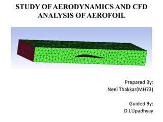
  • 1. STUDY OFAERODYNAMICS AND CFD ANALYSIS OF AEROFOIL Prepared By: Neel Thakkar(MH73) Guided By: D.I.Upadhyay
  • 2. Outline Of Presentation Introduction The Atmosphere Aerofoil and terminologies Forces acting on Aircraft Stability of Aircraft CFD analysis of Aerofoil Conclusion References
  • 3. Aerodynamics : Aerodynamics is the study of objects in motion through the air and the forces that produce or change such motion. Chapter 1: INTRODUCTION It is unnecessary that a mechanic be totally versed on Aerodynamics and Theory of Flight. However he must understand the relationships between the atmosphere, the aircraft and the forces acting on it in flight, in order to make intelligent decisions affecting the flight safety of both airplanes and helicopters.
  • 4. The Atmosphere : Air is a mixture of gases composed principally of nitrogen and oxygen. An aircraft operates in the air therefore, the properties of air that affect aircraft control and performance must be understood. Pressure – Atmospheric pressure varies with altitude. The higher an object rises above sea level, the lower the pressure. Density – It varies directly with the pressure and inversely with the temperature. With the same horse power, an aircraft can fly faster at high altitude because of less resistance of air at there. Humidity – Humidity is the amount of water vapor in the air. It varies directly with temperature.
  • 5. BERNOULI'S PRINCIPLE: • Bernoulli's principle states that when a fluid flowing through a tube reaches a constriction or narrowing of the tube, the speed of the fluid passing through the constriction is increased and its pressure is decreased. • In B, air is flowing past a cambered surface, such as an aerofoil, and the effect is similar to that of air passing through a restriction.
  • 6. Chapter 2: Aerofoil  An airfoil is the shape of a wing or blade (of a propeller, rotor or turbine) as seen in cross-section.  An aircraft's wings, horizontal, and vertical stabilizers are built with airfoil-shaped cross sections, as are helicopter rotor blades. Mean camber line Chord line
  • 7. Aerofoil Terminology and Definitions: • Blade span—the length of the rotor blade from centre of rotation to tip of the blade. • Chord line—a straight line intersecting leading and trailing edges of the aerofoil. • Chord—the length of the chord line from leading edge to trailing edge; it is the characteristic longitudinal dimension of the aerofoil section. • Mean camber line—a line drawn halfway between the upper and lower surfaces of the aerofoil. The chord line connects the ends of the mean camber line. The profile thickness and thickness distribution are important properties of an aerofoil section. • Leading edge— the front edge of an aerofoil is known as leading edge. • Flight path velocity—the speed and direction of the aerofoil passing through the air. For aerofoil on an airplane, the flight path velocity is equal to true airspeed (TAS) • Centre of pressure—an aerofoil at an angle of attack α experiences a resultant aero- dynamic force, and the point on the chord through which the line of action passes is called the centre of pressure. • Aerodynamic Centre--It is not the same as the centre of pressure which does move as angle of attack changes. It is the point about which the clockwise and anticlockwise moments remain constant with changing angle of attack.
  • 8. • Angle of attack (AOA)—the angle measured between the resultant relative wind and chord line. The angle of attack is the angle between the chord line and the average relative wind. • Greater angle of attack creates more lift (up to a point). AOA is an aerodynamic angle and not easy to measure. It can change with no change in the blade pitch angle. • When the AOA is increased, air flowing over the aerofoil is diverted over a greater distance, resulting in an increase of air velocity and more lift. As the AOA is increased further, it becomes more difficult for air to flow smoothly across the top of the aerofoil. • At this point, the airflow begins to separate from the aerofoil and enters a burbling or turbulent pattern. The turbulence results in a large increase in drag and loss of lift in the area where it is taking place. • Increasing the AOA increases lift until the critical angle of attack is reached. Any increase in the AOA beyond this point produces a stall and a rapid decrease in lift.
  • 9. Aerofoil Types: • There are mainly two types of aerofoil. 1 Symmetrical Aerofoil 2 Nonsymmetrical Aerofoil (Cambered) Symmetrical Aerofoil • The symmetrical aerofoil is distinguished by having identical upper and lower surfaces. The mean camber line and chord line are the same on a symmetrical aerofoil, and it produces no lift at zero AOA. Most light aircrafts incorporate symmetrical aerofoils in the main rotor blades. Nonsymmetrical Aerofoil (Cambered) • The non symmetrical aerofoil has different upper and lower surfaces, with a greater curvature of the aerofoil above the chord line than below. • The mean camber line and chord line are different. The nonsymmetrical aerofoil design can produce useful lift at zero AOA. • The advantages are more lift production at a given AOA than a symmetrical design, an improved lift-to-drag ratio, and better stall characteristics. • The disadvantages are centre of pressure travel of up to 20 present of the chord line (creating undesirable torque on the aerofoil structure) and greater production costs.
  • 10. Chapter 3: Forces Acting on the Aircraft Types of forces Once an airplane leaves the ground, it is acted upon by four aerodynamic forces; thrust, drag, lift and weight. • Lift—opposes the downward force of weight, is produced by the dynamic effect of the air acting on. The aerofoil, and acts perpendicular to the flight path through the centre of lift. • Drag—a rearward, retarding force caused by disruption of airflow by the wing, rotor, fuselage, and other protruding objects. Drag opposes thrust and acts rearward parallel to the relative wind. • Thrust—the forward force produced by the power plant/propeller or rotor. It opposes or overcomes the force of drag. As a general rule, it acts parallel to the longitudinal axis. However, this is not always the case, as explained later. • Weight—the combined load of the aircraft itself, the crew, the fuel, and the cargo or baggage. Weight pulls the aircraft downward because of the force of gravity. It opposes lift and acts vertically downward through the aircraft’s centre of gravity (CG).
  • 11. 3.1 Lift: • Lift is generated when an object changes the direction of flow of a fluid or when the fluid is forced to move by the object passing through it. The lift generated by an aerofoil depends on such factors as: • Speed of the airflow • Density of the air • Total area of the segment or aerofoil • AOA between the air and the aerofoil • A symmetric aerofoil must have a positive AOA to generate positive lift. At a zero AOA, no lift is generated. At a negative AOA, negative lift is generated. • A cambered or non-symmetrical aerofoil may produce positive lift at zero, or even small negative AOA. • The majority of lift is the result of decreased pressure above the blade, rather than the increased pressure below it.
  • 12.
  • 13. 3.3 Drag: • The force that resists the movement of an aircraft through the air and is produced when lift is developed is called drag. Drag must be overcome by the engine to turn the rotor. Drag always acts parallel to the relative wind. Total drag is composed of three types of drag: friction, induced, and parasite. 3.3.1 Friction Drag: • Profile drag develops from the frictional resistance of the blades passing through the air. • It does not change significantly with the aerofoil’s AOA, but increases moderately when airspeed increases. Profile drag is composed of form drag and skin friction. • Skin friction is caused by surface roughness. Even though the surface appears smooth, it may be quite rough when viewed under a microscope. A thin layer of air clings to the rough surface and creates small eddies that contribute to drag. 3.3.2 Wave drag coefficient: • The rapid increase in the drag coefficient due to the formation of shock waves at high speeds is called wave drag. • Shock waves cause the boundary layer to separate, thus increasing the drag. Wave drag begins at the Mach number for drag divergence Because a subsonic airplane will not fly above MD because the drag is too high.
  • 14. 3.3.3 Induced Drag: • Induced drag is generated by the airflow circulation around the rotor blade as it creates lift. • The lift produced by the blade is perpendicular to the relative wind, the lift is inclined aft by the same amount. The component of lift that is acting in a rearward direction is induced drag. 3.3.4 Parasite Drag: • Parasite drag is present any time the aircraft is moving through the air. This type of drag increases with airspeed. Non-lifting components of the aircraft, such as the cabin, rotor mast, tail, and landing gear, contribute to parasite drag. • While parasite drag can be reduced by reducing the number of exposed parts.
  • 15. 3.3.5 Total Drag: • Total drag for aircraft is the sum of all three drag forces. • As airspeed increases, parasite drag increases while induced drag decreases. Profile drag remains relatively constant throughout the speed range with some increase at higher airspeeds. Combining all drag forces results in a total drag curve. • The low point on the total drag curve shows the airspeed at which drag is minimized. This is the point where the lift-to-drag ratio is greatest and is referred to as L/DMAX. At this speed, the total lift capacity of the aircraft, when compared to the total drag of the aircraft, is most favourable. This is an important factor in aircraft performance • Drag Equation is given by: D=CD × ½ ρ × S × V2
  • 16. 3.3 Weight: • Weight has a definite relationship with lift, and thrust with drag. These relationships are quite simple, but very important in understanding the aerodynamics of flying. • This weight force acts downward through a point called the centre of gravity (CG). The CG is the point at which all the weight of the aircraft is considered to be concentrated. 3.4 Thrust: • To overcome drag and move the aircraft forward, another force is essential. This force is thrust. Thrust is derived from jet propulsion or from a propeller and engine combination. • Jet propulsion theory is based on Newton’s third law of motion. The turbine engine causes a mass of air to be moved backward at high velocity causing a reaction that moves the aircraft forward.
  • 17. There are two types of stability  Static Stability - The initial movement of an object after being disturbed. – Positive Static Stability – returns to position before displacement. – Neutral Static Stability – tendency to remain in displaced position. – Negative Static Stability – tends to continue away from displaced position in same direction.  Dynamic Stability - The behavior of the object over time. – Positive Dynamic Stability – the oscillations dampen themselves out. – Neutral Dynamic Stability – the oscillations carry on with out increasing in severity. – Negative Dynamic Stability – the oscillations increase in severity and diverge. Chapter 4 :Stability  An aircraft must have sufficient stability to maintain a uniform flight path and recover from the various upsetting forces also to achieve the best performance.
  • 19. CH 5: CFD Analysis of Supercritical Aerofoil 5.1 Supercritical Aerofoil • Mach numbers while retaining acceptable low-speed maximum lift and stalls characteristics and focused on a concept referred to as the supercritical aerofoil. • This characteristic aerofoil shape, based on the concept of resident supersonic flow with isentropic recompression, was considered by a large leading-edge radius, condensed curvature over the middle region of the upper surface, and considerable aft camber.
  • 20. Serial no Input Value 1 Velocity of flow 0.6 Mach or 205.8 m/s 2 Operating temperature 300 k 3 Operating pressure 101325 Pa 4 Turbulence Model transition Spalart-Allmars 5 Density of fluid 1.225 kg/m3 6 Kinematic viscosity 1.4607*10-5 7 Reynolds number 3.5*106 8 AOA 0°-22.5° 9 Fluid Air as an ideal I. INPUTS AND BOUNDRAY CONDITIONS 5.1.1 Input and Boundary conditions It involves inlet, outlet & wall boundary the velocity components are calculated for each angle attack case as follows. All the outermost boundaries are considered as the “Pressure Far Field” boundary conditions in Fluent.
  • 21. II. METHODOLOGY 5.2.1 Model creation • We get the model dimensions through coordinates, from these coordinates get from NASA website; we created a model in catia model as shown in figure 5.1. Thickness 13.9% Camber 1.55% Trailing edge angle 16.7° Lower flatness 9.4% Leading edge radius 2.9% Table 5.2: Aerofoil data Fig 5.1: Aerofoil NACA SC (2) 0714 Model
  • 22. 5.2.2 Mesh generation • Meshed the above shows computational domain using Hyper Mesh 11. It has been created the surface meshes with the trais and the volume mesh is created with tetras. • The meshed model contains top surface, bottom surface, computational domain wall; pressure far filed wall and Pressure outlet surfaces. • It has 404867 tetra elements and 55918 nodes. • Meshed model shown in figure below.
  • 23. 5.2.3 Solver step • Setting up of the solver is very important in any of the fluid flow problem; the solver setting indicates the method and also a procedure for solving (analysis) the problem. • The solver settings applied in Fluent for the simulations of Aerofoil are tabulated in Table 5.3. Table 5.3 Solver Setting Applied For Aerofoil
  • 24. III. RESULTS AND DISCUSSIONS From the contours, we see that there is a region of high pressure at the leading edge (stagnation point) and region of low pressure on the upper surface of aerofoil. From Bernoulli equation, we know that whenever there is high velocity, we have low pressure and vice versa. 5.3.1 At 0° Angle of attack : • Figure shows that the maximum pressure and pressure appeared at leading edge is 29079.86Pa and the pressure appeared at trailing edge is 2390.27Pa and the Pressure Drag is measured by taking difference in static pressure at leading edge and trailing edge. • More difference means more pressure drag. So the pressure drag is 26689.59Pa and the average pressure around the aerofoil wall is -2847.358Pa. The static pressure at upper surface of the aerofoil wall -5950.22Pa and at lower surface is -5950.22Pa so the Lift of the aerofoil is not much high enough at this angle of attack.
  • 25. 5.3.2 At 12° angle of attack : • The below figure shows that the contours of static pressure at the aerofoil wall and centre domain of the aerofoil. • It shows that the maximum pressure is appeared in plane is 41358.3Pa and pressure appeared at leading edge is 27624.89Pa and the pressure appeared at trailing edge is -3765.74Pa so the Pressure Drag is 31390.63Pa and the average pressure around the aerofoil wall is-2696.56Pa. • The static pressure at upper surface of the aerofoil wall -7689.6Pa and at lower surface is -3765.74Pa • So the Lift of the aerofoil is more than the drag.
  • 26. 5.3.3 At 20° Angle of attack: • The below figure shows that the contours of static pressure at the aerofoil wall and centre domain of the aerofoil. It shows that the maximum pressure is appeared in plane is 69675.74Pa and pressure appeared at leading edge is 29648.28Pa and the pressure appeared at trailing edge is -4747.38Pa. • The average pressure around the aerofoil wall is -1881.45Pa and Pressure Drag is 34395.65Pa. The static pressure at lower surface of the aerofoil wall 2963.31Pa and at upper surface is -7710.69Pa • So the Lift of the aerofoil is more.
  • 27. 5.3.4 At 22.5° angle of attack : • The figure shows that the contours of static pressure at centre domain of the aerofoil. The maximum pressure is appeared in plane is 78052.59Pa and pressure appeared at leading edge is 29005.72Pa and the pressure appeared at trailing edge is 309.223Pa. • So the Pressure Drag is also reduced as compare previous angle of attack, pressure drag is 28696.5Pa and the average pressure around the aerofoil wall is-1881.45Pa. • The static pressure at upper surface of the aerofoil wall 3039.725Pa and at lower surface is 2789.5Pa • So the Lift of the aerofoil is decrease.
  • 28. • The figure 5.7 shows that the angle of attack v/s Lift and Drag coefficient plot. Drag coefficient will slightly increases with angle of attack but not like lift and the turbulence will be there at trailing edge but less as compared to leading edge. The pressure at trailing edge is compared to leading edge is very less and maximum velocity of the aerofoil is less at trailing edge so drag will not increases as like lift but drag will also be there. • After the 20° angle of attack pressure on upper surface of the aerofoil at leading edge is more as compare to lower surface of the aerofoil at leading edge so drag is increases gradually from 20° angle of attack.
  • 29. • Lift coefficient will increases as the angle of attack increases because pressure on lower surface of the aerofoil at leading edge is more as compare to pressure on upper surface and turbulence is very high on the lower surface of the aerofoil at leading edge so Lift of the aerofoil will occur. • Lift of aerofoil is increased up to 20° angle of attack, after this angle of attack lift coefficient decreases gradually because the pressure on lower surface of the aerofoil is decreases than the upper surface of the aerofoil.
  • 30. IV. CONCLUSION • It is found that the static pressure on the lower surface of the aerofoil at leading edge side is greater than static pressure on the upper surface of the aerofoil so the lift of aerofoil is increases gradually till 20° angle of attack, from this angle of attack the pressure on lower surface of the aerofoil is reduced than upper surface so lift of the aerofoil is decreasing and drag of the aerofoil is increasing. • Pressure Drag is calculated by taking difference in static pressure at leading edge and trailing edge. • More difference means more pressure drag. • At 20° Angle of attack pressure drag will increase and form 22.5° angle of attack pressure drag will decrease continuously.
  • 31. References: [1] Whitcomb, Richard T.: Review of NASA Supercritical Airfoils. ICAS Paper No. 74-10, Aug. 1974 [2] Gaurav saxena , Mahendra Agrawal, Aerodynamic analysis of NACA 4412 airfoil using CFD, International Journal of Emerging Trends in Engineering and Development Issue 3, Vol.4 (June-July 2013) ISSN 2249-6149. [3] The Element 0f Aerofoil and Airscrew theory By H. Glauert. [4] Karna S. Patel, Saumil B. Patel, Utsav B. Patel, Prof. Ankit P. Ahuja, “CFD Analysis of an Aerofoil” International Journal of Engineering Research ISSN: 2319-6890), 2347- 5013.Volume No.3, Issue No.3, pp: 154-158 01 March 2014.