Unit-IV; Professional Sales Representative (PSR).pptx
Est 6
1. EMBEDDED SYSTEMS TUTORIAL6- INTERFACING 7
SEGMENT DISPLAY WITH AVR
Hii… friends its our next AVR tutorial this time we are going to discuss about interfacing of 7 segment
display with a AVR. You must have seen 7 segment display in you house hold inverters, in a zerox
machine or even on your microwave oven. So in this tutorial , We will discuss about 7 segment display ,
its types and its interfacing with AVR along with source code so have a look…
INTROUCTION
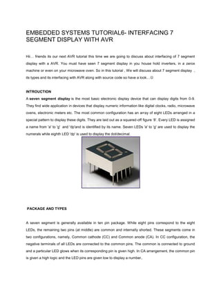
A seven segment display is the most basic electronic display device that can display digits from 0-9.
They find wide application in devices that display numeric information like digital clocks, radio, microwave
ovens, electronic meters etc. The most common configuration has an array of eight LEDs arranged in a
special pattern to display these digits. They are laid out as a squared-off figure ‘8’. Every LED is assigned
a name from 'a' to 'g' and 'dp'and is identified by its name. Seven LEDs 'a' to 'g' are used to display the
numerals while eighth LED 'dp' is used to display the dot/decimal.
PACKAGE AND TYPES
A seven segment is generally available in ten pin package. While eight pins correspond to the eight
LEDs, the remaining two pins (at middle) are common and internally shorted. These segments come in
two configurations, namely, Common cathode (CC) and Common anode (CA). In CC configuration, the
negative terminals of all LEDs are connected to the common pins. The common is connected to ground
and a particular LED glows when its corresponding pin is given high. In CA arrangement, the common pin
is given a high logic and the LED pins are given low to display a number .
2. HOW IT WORKS
Now let us suppose a digit is to be displayed on the 7 segment. Suppose the digit is 1 in
such case LEDS corresponding b and c should glow, so we can say foe each and every
digit a specific set of LEDs has to glow . the LEDs to be golw with corresponding digits
Are as shown.
3. INTERFACING WITH AVR MICROCONTROLLER
Here is step wise process for inTERfacing a 7 segment display with AVR
microcontroller( ATMEGA 16)
SETP 1
CICUIT CONNECTION
Here we are using a common anode 7 segment display.
Connect your 7 segment display with the atmega 16 as per the connections shown in
the diagram below
4. STEP 2
SOURCE CODE
Create the new project in AVR STUDIO4 and compile the code written below-
/*
A simple program for interfacing common anode seven segment display with AVR
microcontroller
9. In this program first we have created a function to display digits named
seven_segment_display, then we have passed two argument first to display numbers
and other to display decimal point if we want. We are going to connect our 7 segment at
PORT C, so we will make it output port and after that the corresponding pins connected
to 7 segment pins are set to high or low according to number to be displayed. This
program will display the no from 0 t0 9 and as it reaches to 9 , it will be reset to 0. You
can change numbering sequence or display only odd or odd number or whatever you
want just by some small changes in the source code according to your task.
Now burn the microcontroller with the hex file generated and power up your
circuit , you will see numbers displaying from 0 to 9.
So we have learnt the basics of 7 segment display interfacing, we can more 7 seven
segment display with a AVR but for that we will need multiplexing technique, we will
discuss multiplexing in upcoming tutorials but before that we have to discuss about
TIMER in AVR so in next tutorial we will discuss about TIMER s