
Recommandé
Contenu connexe
Tendances
Tendances (19)
Similaire à Physics Revision Notes Term 1.pdf
Similaire à Physics Revision Notes Term 1.pdf (18)
Dernier
Dernier (20)
Physics Revision Notes Term 1.pdf
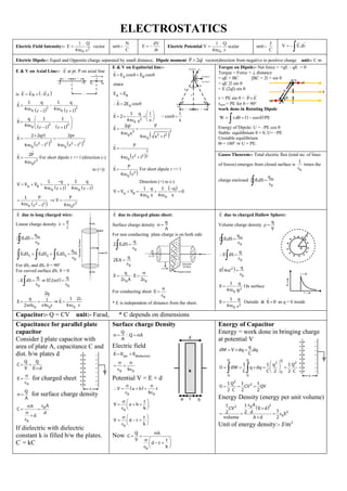
- 1. ELECTROSTATICS Electric Field Intensity:- 2 0 1 Q E 4 r = vector unit:- N C dV E dr = − Electric Potential 0 1 Q V 4 r = scalar unit:- J C V E.dr = − Electric Dipole:- Equal and Opposite charge separated by small distance, Dipole moment P 2ql = vector(direction from negative to positive charge unit:- C m E & V on Axial Line:- E at pt. P on axial line is ( ) B A E E E = + − ( ) ( ) = − − + 2 2 0 0 1 q 1 q E 4 4 r l r l ( ) ( ) = − − + 2 2 0 q 1 1 E 4 r l r l ( ) ( ) = = − − 2 2 2 2 2 0 0 2 2qrl 2pr E 4 r l 4 r l = 3 0 2P E 4 r For short dipole r >> l (direction (-) to (+)) ( ) ( ) − = + = + + − A B 0 0 1 q 1 q V V V 4 4 r l r l ( ) = − 2 2 0 1 P 4 r l = 2 0 P V 4 r E & V on Equitorial line:- ( ) = + = = = = = = + A B A B A 2 0 3 3 2 2 0 0 E E cos E cos since E E E 2E cos 1 q l l E 2 cos 4 x x x 2ql P E 4 x 4 x l ( ) = + 3 2 2 2 0 P E 4 r l ( ) = 3 0 P E 4 r For short dipole r >> l Direction (+) to (-) ( ) − = + = + = A B 0 0 q 1 q 1 V V V 0 4 x 4 x Torque on Dipole:- Net force = +qE – qE = 0 Torque = Force × ⊥ distance = qE × BC [BC = 2l × sin θ = qE 2l sin θ = E (2ql) sin θ τ = PE sin θ = P E τmax = PE for θ = 90o work done in Rotating Dipole ( ) W d 1 cos PE = = − Energy of Dipole: U = –PE cos θ Stable equilibrium θ = 0, U= –PE Unstable equilibrium Θ = 180o ⇒ U = PE. Gauss Theorem:- Total electric flux (total no. of lines of forces) emerges from closed surface is 0 1 times the charge enclosed = in 0 q E.dS E due to long charged wire: Linear charge density = q l = in 0 q E.dS + + = in 1 2 3 0 q E.dS E.dS E.dS For dS2 and dS3 θ = 90o For curved surface dS1 θ = 0 = 0 q E dS ⇒ ( ) = 0 q E 2 rl = = 0 0 2q q l E 2 rl 4 r ⇒ = 0 1 2 E 4 r E due to charged plane sheet: Surface charge density = q A For non conducting plate charge is on both side = 0 q 2 E.dS = 0 q 2EA = 0 q E 2 A = 0 E 2 For conducting sheet = 0 E * E is independent of distance from the sheet. E due to charged Hallow Sphere: Volume charge density = q V = in 0 q E.dS = 0 q E dS ( ) = 2 0 q E 4 r = 2 0 1 q E 4 R On surface = 2 0 1 q E 4 r Outside & = E 0 as q = 0 inside Capacitor:- Q = CV unit:- Farad, * C depends on dimensions Capacitance for parallel plate capacitor Consider || plate capacitor with area of plate A, capacitance C and dist. b/w plates d = = Q Q C V E d = 0 E for charged sheet = Q A for surface charge density = = 0 0 A A C d d If dielectric with dielectric constant k is filled b/w the plates. C’ = kC Surface charge Density = = Q Q A A Electric field = + air dielectric E E E = + 0 0 k Potential V = E × d ( ) = + + 0 0 V a b t k = + + 0 t V a b k = − + 0 t V d t k Now = = − + 0 Q A C V t d t k Energy of Capacitor Energy = work done in bringing charge at potential V = = q dW V dq .dq C = = = = Q Q Q 2 2 0 0 0 1 1 q 1 Q U dW q dq C C 2 2 C = = = 2 2 1 Q 1 1 U CV QV 2 C 2 2 Energy Density (energy per unit volume) ( ) = = = 2 2 0 2 0 A 1 1 E d CV 1 2 d 2 E volume A d 2 Unit of energy density:- J/m3
- 2. CURRENT ELECTRICITY Electric Current: q i t = , unit - Ampere * Scalar quantity nAle i q / t t = = Current I = neAVd eV I neA ml = 2 I ne A V ml = V = IR 2 V ml R I ne A = = Mobility d V E = (m2 /sV) A – Area n – number of free electrons in unit volume resistivity ρ = RA l ρ 2 m ne = Also J E = I J A = = current density (vector) Drift velocity:- v u a = + if u = 0 –14 relaxationtime (10 s) − d V a = Also ma = eE = f eE a m = d eE V m = (10–5 m/s) as V = Exl d eV V ml = Temperature dependence of resistivity Electric Energy & power Colour Coding of Resistor with increase in temperature conductors : decrease. inc. semiconductors; n increase dec Power = Energy / Time = Work done / Time It is a scalar quantity 2 2 V E V.I.t I Rt t R = = = 2 2 V P V.I I R R = = = 1 unit = 1 KWh Series combination of resistance:- R = R1 + R2. Current same Parallel combination of resistance:- 1/R = 1/R1 + 1/R2 Voltage same E = V + ir charging E = V – ir discharging KIRCHOFF’S LAW i. i = 0 Junction law ii. iR = E = 0 Voltage law Cell in series I = nE /nr + R Cell in parallel nE i r nR = + Meter Bridge: Let Unknown Resistance = X R l X 100 l = − R(100 R) X l − = Resistivity RA L = Meter bridge in most sensitive when null pt. in middle. Wheatstone Bridge: Balance condition P / Q = R / S Potential at A & B same at null pt. Position of Galvanometer & battery can be interchanged at null pt. Potentiometer: Principle:- If constant current flows through wire of uniform cross section, then drop in directly proportional to length of that portion E K L = = Potential gradient When K1 inserted then E1 = K × L1 When K2 inserted then E2 = K × L2 1 1 2 2 E L E L = When only K1 is inserted then E = K × L1 When K1 and K2 both are inserted then V = K × L2 = E – r 1 2 1 l r R l = − Advantage of Potentiometer over voltmeter:- 1. Preferred over voltmeter as it give exact reading draw no current 2. Sensitivity increase with increase in length 3. A small P. D can be measured accurately with the help of potentiometer. The resistance of voltmeter is high but not infinity to work as an ideal voltmeter. 4. The internal resistance of a cell can be measured with the help of potentiometer.
- 3. MOVING CHARGES & MAGNETISM Magnetic Field:- Produced by magnet, moving charge, Vector quantity. Unit:- Tesla (weber/m2 ), gauss (maxwell/cm2 ) IT = 104 G Oested Experiment:- Current carrying conductor produces magnetic field. Bio Savart Law:- It gives M.F. at a point around current carrying conductor. idl sin dB r = 0 2 4 TmA − − = 7 1 0 10 4 μ0 – Permeability of free space Direction of B:- Perpendicular to dl and r. B = 0 if sin θ = 0 B = max sin θ = 1 θ = 90o Vector Form idl r dB r = 0 3 4 Ampere’s Circuital Law:- B.dl i = 0 The line integral of magnetic field B for any closed circuit is equal to μ0 times current i threading through this closed loop and this closed loop is called Amperian loop. B. Due to Infinitely Long Wire:- Magnetic field at P due to wire B.dl i = 0 B dl i = 0 B(2πr) = μ0i l B r = 0 2 4 Direction:- Right Hand Thumb Rule curly finger gives field direction if thumb of right hand points current outside Mag. Field At Centre of Coil:- o idl sin dB r = 0 2 90 4 i B dB dl r = = 0 2 4 ( ) i r r = 0 2 2 4 i B r = 0 2 or Ni B r = 0 2 Direction:- Right Hand Thumb Rule. B. due to Solenoid:- Bdl B.dl cos = N – Total Turns d a B.dl i = 0 ( ) b c d a a b c d B.dl B.dl B.dl B.dl Ni + + + = 0 ( ) b a B.dl Ni + + + = 0 0 0 0 b a B. dl Ni = 0 B.L ni = 0 ⇒ ∴ B = μ0ni N n L = (Turns per unit Length) On Axis of Coil:- o idl sin dB x = 0 2 90 4 B dB sin = ( ) i a a . x x = 0 2 2 4 ( ) / Nia B a r = + 2 0 3 2 2 2 2 Force on charge in Electric field:- F = qE (both for rest & motion) Magnetic Field:- F = qV Bsin θ (only for moving charge) B. Due to Toroid:- (Closed solenoid) B.dl Ni = 0 ( ) B r Ni = 0 2 Ni N B n r r = = 0 2 2 B ni = 0 [at P] Lorentz Force:- F = qE + qvB sin θ = q (E + vB sin θ) Cyclotron:- Used to accelerate charge Particles. Principle:- The repeated motion of charged particles under mag. & ele. field accelerates it. E.F. provides energy while M.F. changes direction. Construction:- Dees, Sources, M.F., R.F. Oscillator Working:- max Max KE mv = 2 1 2 qBr m m = 2 1 2 q B r K.E. m = 2 2 2 1 2 Force b/w 2 parallel current carrying wire:- Force acting on a due to b. o i F i l sin r = 0 1 2 2 90 4 i i F r = 0 1 2 2 4 (For unit Length) By Flemings LHR force is of attraction for same direction of current and force of repulsion for opposite direction of current. if i i A, r m. = = = 1 2 1 1 then F = 2 × 10⁻⁷ N. Current Sensitivity:- Deflection per unit current s BAN I i C = = Radian Ampere Moving Coil Galvanometer:- Device to detect & measure electric current. Principle:- Current loop experience torque in uniform M.F. Construction:- Light Coil, concave magnetic Poles → radial field. Theory:- Deflecting torque = Restring force (torque) B × i × N × A × sin θ = CØ (θ = 90o ) as field is radial ∴ B AiN = CØ ⇒ C i ABN = Torque Experienced By a Current loop in uniform Magnetic Field:- τ = F × ⊥ distance = Bil × bsin θ τ = Bi A sin θ For N Turns:- τ = BiNa sin θ Voltage Sensitivity:- Deflection per unit voltage s s I BAN V R V iR CR = = = = Radian Volt Limitation:- Only charged particles can be acceleration For circular path:- mv qvB r = 2 ⇒ mv r qB = ⇒ r ∝ v q B r K.E. m = 2 2 2 1 2 Time period = Distance / Velocity = 2πr / v ⇒ T = 2πm / qB Frequency of Revolution:- f = 1/T = qB/2πm Application:- For nuclear reaction & other research purpose.
- 4. Conversion of Galvanometer into Ammeter:- (i – ig)S = ig.G g g i .G S i i = − {For Ideal Ammeter R = 0} Conversion Into Voltmeter:- By connecting high resistance in series {For Ideal voltmeter, R = ∞} ( ) g V i R G = + ( ) g V R G i = + ELECTROMAGNETIC INDUCTION (E.M.I) The phenomena of producing induced current due to change in magnetic flux is called electromagnetic induction. Faraday Law:- (i) Change in magnetic flux induces current which last till there is change. (ii) d e dt − = Lenz’s Law:- Induce current opposes the factor due to which it is produced. acc. to law of conservation of energy. Method of producing emf:- d dBAcos e dt dt − − = = Induced current / charge:- d e d dq d e ,i , dt R Rdt dt Rdt − − − = = = = d dq R − = Motional emf:- The emf induced due to motion of a conductor in M. field. Motional emf:- d e dt − = dB.A dt − = BdA Bldx dt dt − − = = e Bvl = − Direction = Anticlockwise Force:- Bvl i R = Bvl F Bil B l R = = − B vl F R − = 2 2 Power:- P = Fv B v l P R − = 2 2 2 Rotating rod:- d e dt − = dBA e dt − = BdA e dt = B L e = 2 2 e B L = 2 1 2 or e B R = 2 1 2 No. of spokes is increased emf remain same. Eddy Current:- The circulating induced current in a oscillating metallic block kept in magnetic field. In can be reduced by using laminated core, or cutting slots in block. Application:- (i) Magnetic brakes (ii) Induction furnace (iii) Dead beat galvanometer Self – Induction:- Change in current in a coil, induced current is produced which opposes the change in same coil. Unit:- L = 1 Henry (H) Dimension Formula:- [ML2 T–2 A–2 ] Solenoid:- ϕ = Li ϕ = BAN = (μ0niA) × N Li = μ0n2 × i × A × l (n = N/l) L = μ0n2 Al Mutual – Induction:- when the change in current in primary coil induces current in secondary coil. ϕ ∝ i ϕ = Mi Unit – Henry ∈0 = Farad/m μ0 = Henry/m Solenoid:- B2 = μ0n2i2 ϕ = B2AN1 ϕ = (μ0n2i2)AN1 ϕ = Mi2 Mi2 = μ0n1n2Ali2 M = μ0n1n2Al *No. of turns is double than inductance become four times ( L ∝ n2 ). Electrical Resonance:- F LC = 1 1 2 Power in A.C. circuit:- P V i cos = 0 0 1 2 V i P cos = 0 0 2 2 RMS RMS P V i Cos = R Cos Z =
- 5. MAGNETISM & MATTER Properties of Magnet: 1. Magnets have north pole and south pole. 2. Likes poles repel & unlike attract each other. 3. Freely suspended magnet rests in N – S direction. 4. Monopole do not exist. 5. Mag. Length is eq to 0.84 times of their geometric length. Permanent Magnets are made up of steel: Hysteresis Loop / curve: The graph plotted b/w external field (H) & mag. induction (B) is called “BH curve ‘or hysteresis Loop. Energy Loss: Work done (energy loss) in magnetization and demagnetization is eq. to area of BH curve. Magnetic Material: Paramagnetic 1. odd no of e– in outer most orbit & possess net dipole moment. Diamagnetic 1. Even no of e– and possess net dipole moment is 0. Ferromagnetic 1. Ferromagnetic materials have some unpaired electrons so their atoms have a net magnetic moment. They get their strong magnetic properties due to the presence of magnetic domains. Magnetic Dipole Moment: N 2l → S M = m2l unit: Am2 m → pole Strength. M → Magnetic Dipole Moment Elements of Earth’s magnetic field: 1. Angle of Dip: Angle b/w horizontal line & mag. meridian as a freely suspended magnet. 2. Angle of Declination: Angle b/w geographical meridian & mag. meridian is called Angle of Declination 3. Horizontal Intensity of Earth Mag. The horizontal component of to. Earth’s field at any point is called horizontal intensity ( ) 2 2 2 V H V H B Bsin tan ,B (B ) B B Bcos = = = + 2 2 H V B B B = + M. Due to Current Loop: When current is passed through a loop it, behaves like a magnet. (M = iA) = current × Area, M = NiA ⸫ 2 q evr M ( r) t 2 = = {for e- , v = 2r/t} Magnetic Dipole Moment of a revolving: ( ) 2 q M iA r t = = = evr 2 {for e- , v = 2r/t} 2. Aligns || to field & get weakly magnetized along ext. field. 2. Align ⊥ to ext. field. 2. When a magnetizing force is applied, the domains become aligned to produce a strong magnetic field within the part. Magnetic Field Intensity due to magnetic Dipole: 1. On Axial line: 0 3 2M B 4 r = 2. On Equatorial line: 0 3 M B 4 r = Magnetic Field of Earth: Torque Acting on dipole in Mag. field: f dis. = = mB2 l sin = m2 lBsin = MBsin ⸫ MBsin = →Torque is ⊥ to mag. field and mag. dipole moment (M) → max = MB (sin = 1), = 90° {Due to torque rotation motion or liner. } → min = 0 = (sin = 0) , = 0 3. Mag. field pass through substance 4.Increase with decrease in temp. 3. Mag. field repelled by substance. 4. Increase with increase in temp 3. Temp. at which ferromagnetic substance becomes paramagnetic called curie Temperature. Work done in Rotating the Dipole: W = MB [cos1 – cos2] Electromagnets: Are prepended by passing electric current in a solenoid. The magnet lasts till the current is passed. It can be increased by: 1. Increasing number of turns. 2. Increasing current. 3. using soft iron core.
- 6. ALTERNATING CURRENT (A.C) TRANSFORMER: - It is a device use the change AC voltage. Principle: It is based on principle of mutual induction. Construction: two coil primary & secondary Step up: Increase voltage (k>1) and decrease current. Step down: decrease voltage (k < 1) and increase current. Theory: p s S p p s i V N K V N i = = = 100% output input = A.C. Generator :- It is a device which convert mechanical energy into electrical energy. Principle: It is based on principle of electromagnetic induction. Construciton: (i) Arumature coil. (ii) Field magnet (iii) Slip ring (iv) Brushes . d e dt − = – cos dBA t e dt = e = BA(–ωsinωt) e = BAN ωsin ωt emax = e0 = BANω e = e0sinωt Alternating Current: - D.C – Direction & magnitude are fixed. A.C – Change in both magnitude and direction. HALF– CYCLE: 0 V Vavg. = avg 0 0 1 V . V sin d = av 0 0 1 V V cos = − 0 av V V cos cos0 − = − 0 0 av av 2V 2I V or I = = Full Cycle: Vav = 2 0 1 Vd 2 2 avg 0 0 1 V V sin d 2 = ( ) 2 0 avg 0 V V cos 2 = − ( ) ( ) 0 0 avg V V V cos2 cos 1 1 2 2 = − + = − + avg avg V 0 or I 0 = = Root mean Square: 2 2 RMS 0 1 V V 2 = 2 2 2 2 2 2 RMS 0 0 0 1 1 V V V sin d 2 2 = = 2 2 2 2 0 0 RMS V V 1 cos2 V ( ) sin 2 2 2 − = = = 0 0 RMS RMS V I V or I 2 2 = = A.C. Circuit: - Pure Resistive Circuit: (Circuit containing resistance) 0 V V sin t R R = 0 0 i i sin t V V sin t = = V I Resistance is independent frequency of A.C. Pure capacitor circuit (circuit containing capacitor only) Q = CV d dV C dt dt = , d i C dt = (V0 sinωt) 0 d i CV sin t dt = ωCV0 cosωt 0 V i sin( t / 2) 1 C = + 0 V i 1 C = Pure inductive circuit: V = V0 sin ωt Ldi V dt = Vdt di L + = 0 V sin tdt di L = ( ) 0 0 V V di sin tdt cos t L L = = − Series LCR circuit: - 2 2 2 R v V (Vc Vc) = + − 2 2 2 L C (IZ) (IR) (IX IX ) = + − 2 2 L C Z R (X X ) = + − 2 2 1 Z R L C = + − 1 L C tan R − = ⇒ L C X X tan R − =