SlideShare une entreprise Scribd logo
1  sur  16
Télécharger pour lire hors ligne
CHAPTER - 16
DOZER AND RIPPER
A bulldozer is a pendant attachment mounted on crawler and wheel tractors. In laying a
road bed, bulldozers are employed in opencast mines to dig and transport soil from cuts
to a pile, build fills, push soil from cuts to spoil banks. At stockpiles and construction
sites, bulldozers transport, pile and load crushed stone, sand, gravel and other loose
materials, develop small gravel and sand quarries and supply stone material to the feeding
devices of mixers. The main function of dozer used in open cast mine is to make the road
for the excavating and transport machinery. Like shovel and dumper, it is one of the main
equipment used in open pit mining operation. The use of bulldozers for moving soil and
loose construction materials is highly expedient at distances less than 100 meters.
Bulldozers can erect fills and dig cuts to a height or to a depth of up to 3 meters. It is
powered by diesel engine and power transmission through hydraulic drive. The dozers
are tractors equipped with a front pusher blade that can be raised or lowered by hydraulic
cylinders for digging and pushing the material. The straight dozer is used for pushing
material in a straight path, especially when operating in a self-cut slot. Angling dozers
have blades that may be set an angle to cast dirt to either side while the tractor moves
forward. Crawler tractors carry most of the bulldozers intended for excavation or heavy
pushing. Wheel mounted dozers are mainly used for spreading and backfilling loose
material.
The blade can be controlled vertically or its angular movement by means of hydraulic
actuators. The dozer is powered by a turbo-charged diesel engine. The usual operating
weight of a dozer varies from 20 ton to 50 ton.
DOZER
Dozer classification
The dozers which are commonly used in open pit mining operation are the following
types:
1. Straight dozer or bull dozer, 2. Angle dozer, 3. Tilt dozer
Straight dozer is the conventional dozer with a cutting edge and blade at right angle to the
longitudinal axis of the dozer. The blade can be raised, lowered and tilted slightly but
cannot be angled to the direction of travel. This type of dozer is used for pushing the
material in a straight path, specially when operating in a self-cut slot.
In an angle dozer, the blade can be turned at an angle to the direction of travel as shown
in figure. Hydraulic cylinders generally activate the blade. A particularly important
feature is that it can throw off a window on one edge of the blade, a feature required for
grading haul roads. It is also useful in cutting away the toes of earth embankments or
making hillside cuts. The blade is wider than a straight dozer to enable it to cut a full
width path when angled. The bottom of the moldboard and the edge are flared out at the
lower corners so as to make a full, sharp edged cut when side casting. This causes some
undercutting of edges in straight work. The angled position of the blade add a sideward
movement of the load to the forward motion which can be utilized in leveling and
changing slopes whose is across the path of the machine, in crowning roads, in side
casting earth back into small trenches, and in making shallow ditches.
The tilt dozer is the modification of straight dozer which has a blade that can be pitched
through vertical arc of a few degrees when top of the blade is pitched to the rear. It cuts
better for hard material. The push dozer has a blade that has been reinforced at the center
with heavy steel plate. The shape and size of the blade is such that it can make contact
with the rear end of a scraper. The primary purpose of the push dozer is to make contact
with the scraper push back so as to combine its drawbar pull with that of the scraper to
speed up the loading of the scraper.
The U-bladed dozer has the sides advanced farther than the center. This makes it possible
to transport large load by reducing the side spill. The pointed corner assists penetration in
hard soil and under stumps and boulders.
The dozer may be wheel mounted and crawler mounted. However, crawler mounted
dozer is mostly used. The main components of dozer are blade, arms, undercarriage unit,
transmission system and blade operation system.
The blade has a rectangular base and the back structure with a knife-edge riveted to the
bottom part. The body is steel structure and edge that is projected ahead is made of hard
steel. The dimensions of the blade may be 4260  1060 mm, 3460  1280 mm. etc. The
edge is usually three pieces, a wide center and two corners, which are bolted or riveted.
They are of reversible type. The front of the blade is called moldboard and is concave and
sloped back. As the blade is pushed into the ground, the knife edge normally cuts and
breaks up the dirt that is pushed up the curve of the moldboard until it falls forward.
The material being pushed ahead of the blade is thus kept more or less in rotary
movement, which tends to even up the load and offer less friction and larger load than
would be obtained with the flat vertical moldboard (Fig. a). If the profile blade is
incorrectly selected, then, as the dragging prism is being formed, the cut-off soil does not
move upwards over the blade surface, but budges the soil mass that forms the dragging
prism (Fig. b). This causes the intensive friction between the soil particles. The corner
pieces of the blade wear fastest and are sometimes built up by welding until whole edge
is so worn as to need reversing or replacing.
The rams provided with the dozer are of two types Push arm and Pitch arm. The push
arms are heavy, hollow beams extending from a hinged connection with the tractor to the
bottom of the blade. The pitch arm helps in controlling the pitch and tilts the dozer blade.
The pitch arms are diagonal braces between the push arm and the top of the blade. They
brace the blade against loads above the line of the push arms and provide means of
regulating the pitch and the tilt of the blade. They may be single piece or two-piece
members. Two-piece members help in lengthening or shortening the pitch arm, thereby
helping in forward or backward tipping.
Dozer blade capacity = 0.5  h2
 l  w
Where h is the height of the blade, l is the length and w is the specific weight of the
material. One level or horizontal ground 20% center bulging is found hence the capacity
of the dozer blade is 0.6  h2  l  w.
The capacity of a bulldozer depends on the blade shape, distance through which
the cut-off material is moved, properties of the material, downgrade or upgrade earth
moving. The blade generally pushes 4% more for each percent of down slope as found in
actual practice on a level floor. Therefore, on 25% grade, the machine pushes almost
double the amount of its normal load on the ground. While in uphill, a half load in
comparison with load on level ground is pushed up in a 20% grade and one-fourth of the
load is pushed in a 100% grade. This is mainly to counteract the extra load due to
gradient effect (W sin ) where,  is the gradient. That is why it is required to operated a
bulldozer with variable depth of penetration, beginning with the a depth of 25 – 30%
more than that at the end of the pass. The dragging prism forms over 5 – 7m of distance
covered. The soil is usually cut off in the first or second gear and moved in the third gear
Undercarriage Unit
Figure shows a sketch of the undercarriage unit of a dozer. It consists of two units
mounted on the main frame. The driving sprocket is fitted at the rear end while the idler
wheel is fixed at the front end of the machine.
Undercarriage Unit of Dozer
An endless chain passes over the sprocket and the idler wheel. The track pads which are
usually elevated grouser pads fastened on the track chain. The track chain is driven by the
driving sprocket. The track chain is supported in between the carrier rollers and the track
rollers which are supported on the bearings mounted on the track frame. The tension
adjusting arrangement is fitted between the crawler frame and the idler wheel to adjust
the chain sag.
Technical description (with hydrostatic drive unit of dozer)
A. Make & Model – LIEBHERR 751 / France
Engine: Water cooled Cummins Diesel Engine, 295 kW at 1800 rpm
Engine starting: 24 V dc, electrical system, starter 1 kW, Alternator 50 amps
Attachment Hydraulics:
One double gear pump for operation of front and rear mounted attachments. Maximum
pump capacity – 72 GPM, 160 bar.
Travel drive:
Hydrostatic drive. Each track is driven by one variable displacement swashplate type
pump and two variable displacement motors.
Maxm. pump capacity – 116 GPM, 420 bar
Travel speed – 0 to 9.5 kmph, infinitely variable, forward and reverse.
Maximum drawbar pull – 530 kN, at 1 kmph
Engine speed sensing horsepower control system endures a constant balance between
traction and travel speed, guaranteeing full utilization of engine output and engine
overload does not occur.
Oscillation of track roller frame is  3.50.
& track rollers and 2 carrier rollers.
Track adjustment by grease cylinder. Automatic parking brake application.
B. Make and Model: Hitachi / Japan; FD 30 C (hydrodynamic drive unit of dozer)
Engine: 257 kW
Electrical System: 24 V, 4 Nos. of batteries, Alternator capacity 55 A
Torque Converter:
Type: Single stage
Torque Multiplication: 2.3 : 1.0
Power shift Transmission:
Full power shift, countershaft, constant mesh
3 forward and 3 reverse speed
4.30 kmph (min.) and 12.10 kmph (max.)
Steering:
Hydraulically released, spring applied, oil cooled, multidisc clutches.
Braking:
Hydraulically released, spring applied, contracting band oil bath type, service brake
Parking Brake
Automatic actuation on service brakes with safety transmission lever in lock position or
with engine stop.
Final Drive:
Double reduction 9.30 : 1.0
Undercarriage Unit
Hydraulic track adjusters, Sprockets with bolt on segments.
Length on track on ground: 3150 mm
Gauge: 2135 mm
Ground clearance: 510 mm
Track rollers: 7 nos.
Carrier rollers: 2 nos.
Number of shoes per track: 41 nos.
Track shoes: 610 mm
Ground contact area of track shoes: 38430 cm2
Hydraulic System:
Pump: Gear Type, two section
Large section 346 lpm
Power assist section 27 lpm
Relief valve pressure 160 bar
Actuation: Single lever, power assisted blade control
Hydraulic Tank capacity: 180 litre
Blade Size: (Width × Height) 3975 mm × 1650 mm
Blade capacity: 8.70 m3
Maximum tilt: 900 mm
Maximum pitch: 100
Digging depth: 535 mm
Brake Hydraulic system of dozer
The Brake Hydraulic Circuit diagram of the dozer Model BD-355A is shown in Figure.
Fig. Brake Hydraulic Circuit Diagram
The steering gear pump driven by the prime mover of the dozer through its PTO drive
unit supplies pressurized hydraulic fluid to the steering and braking system of the dozer.
Through flow divider the oil is usually divided into 2 : 1 ratio to the steering and the
braking systems of the dozer (for example in dozer model BD-355A, the 141 lpm oil is
supplied to the steering system; whereas 70.50 lpm is supplied to the braking system).
With the actuation of the brake pedal valve, the oil is directed to the brake booster
cylinder that actuates the steering brakes of the dozer.
The oil flow from the flow divider for the steering circuit is supplied for the actuation of
the steering clutches. The hydraulic circuit diagram of the steering system of the dozer is
shown in Figure.
Fig. Steering Hydraulic Circuit Diagram
Blade control Hydraulic system
The dozer blade and the ripper tool are controlled hydraulically. The pump driven by the
prime mover through the PTO drive of the transmission unit is installed inside the
hydraulic tank. It supplies pressurised hydraulic fluid for the operation of the blade in
different position: lift, lower, float and hold. The blade is also tilted hydraulically.
Fig. Blade Control Hydraulic System
The pressurized oil supplied from the main pump is to the respective control valve after
passing through the check valve that serves to check the backflow of the oil. The suction
valves are provided to make-up oil from the hydraulic tank for the purpose of filling up
oil in the hydraulic cylinders operating the blade and ripper tool of the dozer. During float
position the piston is lowered by the self weight of the blade / ripper tool and therefore,
vacuum is created in the upper chamber of the respective cylinders. In such case the
suction valve draws oil from the hydraulic tank and fills up the void created inside the
cylinder. The quick drop valve prevents the free fall of the blade in its downward
movement by creating back pressure. The pumps and the control valves are located
within the oil tank. The oil filter is located at the top of the tank. A small transmission
pump is also driven the prime mover that supplies pressurized oil for the pilot circuit of
the control valves as well as to the transmission circuit.
Power Transmission System
Figure shows the power transmission system of a dozer. The power delivered by the
engine is distributed for the propel operation and to drive the auxiliary drive unit. For
propel operation of the machine, the power from the hydraulic transmission system
(usually a power shift transmission unit) is transferred to the intermediate gear box. The
intermediate gear unit has two output shafts which are connected with the drive sprockets
through steering clutches and final drive unit (a planetary reduction gear unit).
Fig. Power Transmission system of Dozer
The steering pump and the transmission pumps are driven through auxiliary drive unit of
the power shift transmission. The steering pump supplies pressurized hydraulic fluid for
the actuation of the steering clutches and the brake unit of the final drive assemblies;
whereas the transmission pump delivers pressurized oil for the actuation of the clutches
of the transmission unit. The dozer is steered by controlling the steering clutches
individually. During the straight travel of the machine, both the steering clutches are
engaged; while the clutches at the left or right are engaged or disengaged accordingly to
turn left or right.
Bulldozer Operation
Digging: As bulldozer movers forward and digs, some of the solid cut by the blade will
pile up in front of the blade and move with it, and some of it will drift off the sides,
forming ridges and windrows. The dozer digs and transports much more effectively
downhill than on a level or uphill, and work should be arranged to work down a grade
when it can be done.
Breaking piles: A pile of dirt may be knocked down by walking into it with the blade at
the desired grade, after which it is spread or piled elsewhere. If the heap is too large or
hard for the machine to take it at one pass, or if it is to be preferred in more than one
direction, the first part may be made to cut away part of the pile to grade. If the pile is
very large or hard in proportion to the power of the dozer, the side cut should be repeated
from different angles.
Transporting: While transporting the material, the dirt which flows off the sides of the
blade must be checked or replaced to keep a full load. If the ground is smooth, the blade
is held to just touch it or dig slightly. If the gerund is uneven, an effort is made to cut
enough in humps to replace the dirt that is lost in the hollows or drifts off the sides.
Spreading: When spreading material, the blade is held somewhat above the original
surface so that the dirt can slip under it in a smooth layer on which the machine can work.
A thin layer may be spread to the desired grade, but a thick layer should be built higher to
allow for compaction.
Backblading: After an area has been graded, it may look a bit rough because of small
windrows of loose dirt, grouser prints, and piles left where the dozer turned. These may
be smoothened down by backing over the area with the blade floating. It acts as drag,
smoothing off humps and filling hollows, but does not move enough dirt to change the
grade.
Inspection Before Starting a Dozer
a. Walk around the machine and check for any trace of oil or water leakage.
Examine the connections of the high pressure hoses.
b. Check tightness of the bolts and nuts.
c. Check the engine air cleaner, muffler and track roller supports.
d. Check for damaged electric wires.
e. Check fuel level, water level, oil levels in the machine.
f. Check for the proper functioning of the brakes and the levers..
Procedure for stopping a dozer
a. Cool engine gradually by running it at idling speed for about five to ten minutes.
b. Cut-off the fuel supply of the engine.
c. Turn the starting switch key to the off position and remove key.
Precautions for operation of a dozer
a. Avoid turning the machine on a slope since the machine tends to slip sideways.
b. Always stop the machine on a flat and stable ground.
c. If the temperature of oil in torque converter exceeds the limit, the load on the
machine to be reduced and wait for the temperature to decrease.
d. Never step on the decelerator pedal when going uphill as the engine speed will
decrease and climbing ability will be reduced.
Component wise Maintenance of Dozer
Blade and Arms
a. Any material sticking on the front wall should be scraped off.
b. The edge of the blade should be inspected for its sharpness.
c. Corner pieces should be secured properly.
d. Hinge points of both the pitch arms and the push arms should be inspected for any
play and then to be lubricated properly.
Blade operation control unit
a. Inspect for any leakage of hydraulic oil from the hoses and oil seals in blade
actuating cylinders.
b. Inspect for the smooth operation of the blade lifting cylinders.
c. Inspect the operation of the safety valve and locking valve etc.
d. Clean and replace the oil strainers.
Transmission system
a. Operate the main clutch for the proper functioning.
b. Inspect the intermediate brake by applying it.
c. Oil level in the transmission to be checked.
d. Functioning of the steering clutches to be checked.
e. Driving sprockets to be checked.
Undercarriage Unit
a. The shoe and its profile to be checked.
b. Excessive sagging of the chain should be corrected by providing proper
tensioning.
c. Inspect the conditions of the track and the carrier rollers.
d. Tighten different mountings and the bolts.
Ripper
The main function of the ripper is to loosen the rock. This is necessary for stiff
clay, semi consolidated sand and gravel etc. which needs to be loaded/transported by
scrapper or dozer. Production Ripping is being used more and more today as an
alternative to drilling and blasting with explosive. Due to the increased environmental
pressures and technological developments, there is tremendous improvements in ripping
applications into conditions which formerly required blasting. The material condition of
rock affects its rippability. Although sedimentary formations generally offer the best
opportunity for ripping and igneous and metamorphic the least, decomposed granites and
other weathered igneous and metamorphic rocks often can be ripped economically. The
ripper tool is fitted as an additional attachment at the rear end of the dozer or tractor. The
hydraulic cylinders control the movement of the ripper tool. It may be required to loose
the dense rock with multi-tooth ripper (4 to 5) to raise the output. The loosening
(rippebility) of the rock depends on the direction of ripping with respect to the system of
joints. Ripping at right angles to the direction of main jointing proves to be most
effective. When laminated igneous or metamorphic rocks are ripped, the initial
penetration of the tooth into the ground is very important. To facilitate penetration by
carrying multiple passes of the ripper or by blasting, an advanced cut of the required
depth is made at right angles to the contemplated parallel passes of the rippers. The
length of the cut usually varies from 100 m to 200m.
Ripper Tool
Mainly two types of Ripper tool are used:
a. Hinge Type
b. Parallelogram Type
Each type has special advantage for certain application. Hinge type is used in slabby
material with layers and intermittent ripping jobs. In the hinge type the linkage
arrangement swings the clevis and shank down through an arc, changing the point angle
at various depths. This type offers penetration in the curve and shortens tip and shank
life.
In parallelogram rippers have a rigid mounting with the dozer. The angle remains
constant at any depth and the fixed shank mounting does not allow lateral shank
movement. The hydraulic cylinders form the part of the linkage and they can be adjusted
to change the ripping angle for the best result in different types of material. The depth of
ripping with trailed ripper is normally 0.40 m to 0.50 m, and with self-propelled ripper it
is about 1.0 m to 1.5 m, though it depends on the type of soil on which the ripper works.
1. Hinge type – In this type of ripper, the linkage carries the beam and shank pivots about
a fixed point at the rear end of the tractor. The shank is also fixed to the linkage at a
certain angle. As the shank enters the ground, it penetrates to a depth; the tooth angle is
constantly changing. The hinge type ripper uses a beam capable of holding from one to
five shanks. The shanks can be adjusted to meet the depth and tooth angle requirements
by using a series of holes in the shanks.
Tip angle θ = 200 to 300
Clearance angle φ ≥ 80 to 100
Ripping angle γ = 400 to 600
Smaller φ causes crushing of the rock by its base face of the tip, increases its wear
and resistance of the rock to ripping. The cutting force of the ripper depends on the
ripping angle.
Parallelogram Type Ripper
Make Model: LIEBHERR 751 / France
D – Ground clearance below tool beam – 256 mm
H – Maxm. Clearance under tip – 1100mm
K – Maxm. Penetration – 1760 mm
M – Overall length raised position – 2210 mm
N – Overall length lowered position – 2560 mm
X - Slope angle – 33.50
Y – Shank adjustment angle – 33.50
G - Overall beam width - 1370 mm
Parallelogram Ripper with hydraulic pitch adjustment
Weight of the Ripper complete unit - 6.1 tonne
Ripper:
Make and Model: Hitachi / Japan; VP 30 MH / 3
Type: Parallelogram, Variable pitch
Ripping depth: 750 mm
Ripping width: 2400 mm
Shanks: 3 nos.
Clearance under tooth with ripper raised: 1750 mm
2. Parallelogram type: - This allows the linkage carrying the beam and shank to maintain
an essentially constant tip ground angle regardless of tooth type. Here depth of cut is
more.
3. Adjustable Radial ripper type - It combines the features of hinge type ripper with the
advantage of shank adjustment capability. Such ripper provides a greater range of shank
angles and more reach. It automatically provides more penetration shank angle at the
ground entry and after penetration a more optimum angle for advancement through the
material.
It has the features of both hinge type and parallelogram type. It can vary the tip angle
with respect to vertical for improved penetration and can be hydraulically adjusted while
ripping to provide optimum ripping angle in most of the material.
The impact ripper is mounted to the tractor on a multi shank adjustable parallelogram
frame. It incorporates a hydraulic hammer. The tractor of the dozer provides the hammer
power. The hammer strikes the shank assembly which transmits the hammer force in to
ripping force. These combined with the draw bar pull provides the material penetration
and material sizing capabilities greatly increased over conventional ripping. Advantage is
that there is no noise pollution, no dust, big size of boulders is not there and the
secondary operation is not required. Working on rock requires narrow shoe to reduce
bending or breakage. This should be the single grouser shoe heat treated to a higher
tensile strength and it should provide the better wear resistance as compared to normal
conventional track shoe. The short teeth should be used in extreme impact conditions.
The intermediate teeth are to be used for moderate impact and abrasion conditions. The
long tip is designed for low impact, highly abrasion conditions where the breakage of
rock is not a problem.
The shank protector is a replaceable item which is pinned to the leading edge of the
shank, protecting it from wear and greatly extending the shank life. Ripper shanks are
generally available in two basic designs. One is straight another is curved. Straight shank
provides the lifting action needed in tight, laminated materials plus the ripping ability
required in blocky or shabby material. On the other hand, the curved shanks work well in
less dense material and also produce less ripping resistance.
The cost of ripping depends on what method should be used to get the solid material
into movable form. The advantage of the large ripping tractor over the drilling and
blasting is its ability to loose more materials faster and at a lower cost per m. About 30 to
40% of ripping cost is the cost of its tool.
Attachment of Multi-Shank Ripper with Dozer
1. Main control valve, 2. Divider block, 3. Ripper tilt cylinder (right)
4. Ripper lift cylinder (right), 5. Ripper lift cylinder (left), 6. Ripper tilt cylinder
(left)
Example:
A dozer blade has the dimension of 4500 mm  2000 mm operates on level ground.
What will be the output capacity of the dozer ?
Solution
With reference to the figure,
The output of the dozer blade = 0.5  h2
 L = 0.5  2  2  4.5 = 9.0 m3
Considering 20% of the bulging of the material in front of the blade
The output of the dozer blade = 9  1.2 = 10.8 m3 Ans.

Contenu connexe

Tendances

Excavators: Power Shovel, Backhoe an Front Shovel (by Faisal VA and Karthik V)
Excavators: Power Shovel, Backhoe an Front Shovel (by Faisal VA and Karthik V)Excavators: Power Shovel, Backhoe an Front Shovel (by Faisal VA and Karthik V)
Excavators: Power Shovel, Backhoe an Front Shovel (by Faisal VA and Karthik V)Construction Tech. and Mgmt., VNIT Nagpur
 
Tractor, bulldozer, scraper, ripper_Advanced Construction Technology (Semeste...
Tractor, bulldozer, scraper, ripper_Advanced Construction Technology (Semeste...Tractor, bulldozer, scraper, ripper_Advanced Construction Technology (Semeste...
Tractor, bulldozer, scraper, ripper_Advanced Construction Technology (Semeste...A Makwana
 
Shovel excavator
Shovel excavatorShovel excavator
Shovel excavatorathulya cs
 
Introduction to Conveyors.ppt
Introduction to Conveyors.pptIntroduction to Conveyors.ppt
Introduction to Conveyors.pptKISHAN KUMAR
 
Kope winder or friction winder ppt
Kope winder or friction winder pptKope winder or friction winder ppt
Kope winder or friction winder pptAMIT SAHU
 
Drag line excavator
Drag line excavatorDrag line excavator
Drag line excavatorParth Desani
 
In pit crushing and conveying in surface mines
In pit crushing and conveying  in surface minesIn pit crushing and conveying  in surface mines
In pit crushing and conveying in surface minesSafdar Ali
 
Jack hammer drill
Jack hammer drillJack hammer drill
Jack hammer drillSafdar Ali
 
Mine locomotive ppt (under ground transport system )
Mine locomotive ppt (under ground transport system )Mine locomotive ppt (under ground transport system )
Mine locomotive ppt (under ground transport system )AMIT SAHU
 

Tendances (20)

Excavator machinepptx
Excavator machinepptxExcavator machinepptx
Excavator machinepptx
 
Draglines
DraglinesDraglines
Draglines
 
Bulldozer
BulldozerBulldozer
Bulldozer
 
1.2.2.front end loaders
1.2.2.front end loaders1.2.2.front end loaders
1.2.2.front end loaders
 
Excavators: Power Shovel, Backhoe an Front Shovel (by Faisal VA and Karthik V)
Excavators: Power Shovel, Backhoe an Front Shovel (by Faisal VA and Karthik V)Excavators: Power Shovel, Backhoe an Front Shovel (by Faisal VA and Karthik V)
Excavators: Power Shovel, Backhoe an Front Shovel (by Faisal VA and Karthik V)
 
Tractor, bulldozer, scraper, ripper_Advanced Construction Technology (Semeste...
Tractor, bulldozer, scraper, ripper_Advanced Construction Technology (Semeste...Tractor, bulldozer, scraper, ripper_Advanced Construction Technology (Semeste...
Tractor, bulldozer, scraper, ripper_Advanced Construction Technology (Semeste...
 
Shovel excavator
Shovel excavatorShovel excavator
Shovel excavator
 
Introduction to Conveyors.ppt
Introduction to Conveyors.pptIntroduction to Conveyors.ppt
Introduction to Conveyors.ppt
 
Draglines (fabil & venkatesh)
Draglines (fabil & venkatesh)Draglines (fabil & venkatesh)
Draglines (fabil & venkatesh)
 
Longwall mining[1]
Longwall mining[1]Longwall mining[1]
Longwall mining[1]
 
Bulldozer
BulldozerBulldozer
Bulldozer
 
Kope winder or friction winder ppt
Kope winder or friction winder pptKope winder or friction winder ppt
Kope winder or friction winder ppt
 
Drag line excavator
Drag line excavatorDrag line excavator
Drag line excavator
 
Mining dumper
Mining dumperMining dumper
Mining dumper
 
In pit crushing and conveying in surface mines
In pit crushing and conveying  in surface minesIn pit crushing and conveying  in surface mines
In pit crushing and conveying in surface mines
 
Road Header and Bolter Miner
Road Header and Bolter MinerRoad Header and Bolter Miner
Road Header and Bolter Miner
 
Dragline ppt
Dragline pptDragline ppt
Dragline ppt
 
Jack hammer drill
Jack hammer drillJack hammer drill
Jack hammer drill
 
Scraper
ScraperScraper
Scraper
 
Mine locomotive ppt (under ground transport system )
Mine locomotive ppt (under ground transport system )Mine locomotive ppt (under ground transport system )
Mine locomotive ppt (under ground transport system )
 

Similaire à Dozer & ripper

Chapter 2 -Scrapers.pdf
Chapter 2 -Scrapers.pdfChapter 2 -Scrapers.pdf
Chapter 2 -Scrapers.pdfAnTonkholodov1
 
6 FPM primary tillage presentation.pdf
6 FPM primary tillage  presentation.pdf6 FPM primary tillage  presentation.pdf
6 FPM primary tillage presentation.pdfAshikshaik5
 
Chapter Iii
Chapter IiiChapter Iii
Chapter Iiigalih
 
Equipment for earth work (for civil engineering)
Equipment for earth work (for civil engineering) Equipment for earth work (for civil engineering)
Equipment for earth work (for civil engineering) laxman singh
 
Road making machines in mines
Road making machines in minesRoad making machines in mines
Road making machines in minesVijayant Singh
 
Slotter and plannar machine tools
Slotter and plannar machine toolsSlotter and plannar machine tools
Slotter and plannar machine toolsNavroz Navodia
 
Classification of heavy duty and construction equipment
Classification of heavy duty and construction equipment Classification of heavy duty and construction equipment
Classification of heavy duty and construction equipment debasdessie
 
Earth work equipment
Earth work equipmentEarth work equipment
Earth work equipmentswetha110
 
Power shovel1
Power shovel1Power shovel1
Power shovel1paras6904
 
Types of soil excavation tools and machines in construction
Types of soil excavation tools and machines in constructionTypes of soil excavation tools and machines in construction
Types of soil excavation tools and machines in constructionRanaGhafran
 
Construction equipments
Construction equipmentsConstruction equipments
Construction equipmentsswift_talk
 
rotavator ppt.pptx
rotavator ppt.pptxrotavator ppt.pptx
rotavator ppt.pptxRanit Sarkar
 
Scraper ripper-grader-dozer
Scraper ripper-grader-dozerScraper ripper-grader-dozer
Scraper ripper-grader-dozerSATYANARAYANA I
 

Similaire à Dozer & ripper (20)

Tractors & Related Equipment's (ACE)
Tractors & Related Equipment's (ACE)Tractors & Related Equipment's (ACE)
Tractors & Related Equipment's (ACE)
 
Chapter 2 -Scrapers.pdf
Chapter 2 -Scrapers.pdfChapter 2 -Scrapers.pdf
Chapter 2 -Scrapers.pdf
 
bulldozers.pptx
bulldozers.pptxbulldozers.pptx
bulldozers.pptx
 
6 FPM primary tillage presentation.pdf
6 FPM primary tillage  presentation.pdf6 FPM primary tillage  presentation.pdf
6 FPM primary tillage presentation.pdf
 
Chapter Iii
Chapter IiiChapter Iii
Chapter Iii
 
Excavation in hard rock
Excavation in hard rockExcavation in hard rock
Excavation in hard rock
 
Equipment for earth work (for civil engineering)
Equipment for earth work (for civil engineering) Equipment for earth work (for civil engineering)
Equipment for earth work (for civil engineering)
 
Road making machines in mines
Road making machines in minesRoad making machines in mines
Road making machines in mines
 
Construction equipments and methods
Construction equipments and methodsConstruction equipments and methods
Construction equipments and methods
 
Slotter and plannar machine tools
Slotter and plannar machine toolsSlotter and plannar machine tools
Slotter and plannar machine tools
 
Classification of heavy duty and construction equipment
Classification of heavy duty and construction equipment Classification of heavy duty and construction equipment
Classification of heavy duty and construction equipment
 
Jaw crusher
Jaw crusherJaw crusher
Jaw crusher
 
Earth work equipment
Earth work equipmentEarth work equipment
Earth work equipment
 
Power shovel1
Power shovel1Power shovel1
Power shovel1
 
Types of soil excavation tools and machines in construction
Types of soil excavation tools and machines in constructionTypes of soil excavation tools and machines in construction
Types of soil excavation tools and machines in construction
 
Directional drilling
Directional drillingDirectional drilling
Directional drilling
 
Construction equipments
Construction equipmentsConstruction equipments
Construction equipments
 
earth moving equipments
earth moving equipmentsearth moving equipments
earth moving equipments
 
rotavator ppt.pptx
rotavator ppt.pptxrotavator ppt.pptx
rotavator ppt.pptx
 
Scraper ripper-grader-dozer
Scraper ripper-grader-dozerScraper ripper-grader-dozer
Scraper ripper-grader-dozer
 

Dernier

Processing & Properties of Floor and Wall Tiles.pptx
Processing & Properties of Floor and Wall Tiles.pptxProcessing & Properties of Floor and Wall Tiles.pptx
Processing & Properties of Floor and Wall Tiles.pptxpranjaldaimarysona
 
CCS335 _ Neural Networks and Deep Learning Laboratory_Lab Complete Record
CCS335 _ Neural Networks and Deep Learning Laboratory_Lab Complete RecordCCS335 _ Neural Networks and Deep Learning Laboratory_Lab Complete Record
CCS335 _ Neural Networks and Deep Learning Laboratory_Lab Complete RecordAsst.prof M.Gokilavani
 
MANUFACTURING PROCESS-II UNIT-2 LATHE MACHINE
MANUFACTURING PROCESS-II UNIT-2 LATHE MACHINEMANUFACTURING PROCESS-II UNIT-2 LATHE MACHINE
MANUFACTURING PROCESS-II UNIT-2 LATHE MACHINESIVASHANKAR N
 
Extrusion Processes and Their Limitations
Extrusion Processes and Their LimitationsExtrusion Processes and Their Limitations
Extrusion Processes and Their Limitations120cr0395
 
Introduction and different types of Ethernet.pptx
Introduction and different types of Ethernet.pptxIntroduction and different types of Ethernet.pptx
Introduction and different types of Ethernet.pptxupamatechverse
 
The Most Attractive Pune Call Girls Budhwar Peth 8250192130 Will You Miss Thi...
The Most Attractive Pune Call Girls Budhwar Peth 8250192130 Will You Miss Thi...The Most Attractive Pune Call Girls Budhwar Peth 8250192130 Will You Miss Thi...
The Most Attractive Pune Call Girls Budhwar Peth 8250192130 Will You Miss Thi...ranjana rawat
 
Call for Papers - Educational Administration: Theory and Practice, E-ISSN: 21...
Call for Papers - Educational Administration: Theory and Practice, E-ISSN: 21...Call for Papers - Educational Administration: Theory and Practice, E-ISSN: 21...
Call for Papers - Educational Administration: Theory and Practice, E-ISSN: 21...Christo Ananth
 
(ANJALI) Dange Chowk Call Girls Just Call 7001035870 [ Cash on Delivery ] Pun...
(ANJALI) Dange Chowk Call Girls Just Call 7001035870 [ Cash on Delivery ] Pun...(ANJALI) Dange Chowk Call Girls Just Call 7001035870 [ Cash on Delivery ] Pun...
(ANJALI) Dange Chowk Call Girls Just Call 7001035870 [ Cash on Delivery ] Pun...ranjana rawat
 
Booking open Available Pune Call Girls Koregaon Park 6297143586 Call Hot Ind...
Booking open Available Pune Call Girls Koregaon Park  6297143586 Call Hot Ind...Booking open Available Pune Call Girls Koregaon Park  6297143586 Call Hot Ind...
Booking open Available Pune Call Girls Koregaon Park 6297143586 Call Hot Ind...Call Girls in Nagpur High Profile
 
Call Girls Pimpri Chinchwad Call Me 7737669865 Budget Friendly No Advance Boo...
Call Girls Pimpri Chinchwad Call Me 7737669865 Budget Friendly No Advance Boo...Call Girls Pimpri Chinchwad Call Me 7737669865 Budget Friendly No Advance Boo...
Call Girls Pimpri Chinchwad Call Me 7737669865 Budget Friendly No Advance Boo...roncy bisnoi
 
Sheet Pile Wall Design and Construction: A Practical Guide for Civil Engineer...
Sheet Pile Wall Design and Construction: A Practical Guide for Civil Engineer...Sheet Pile Wall Design and Construction: A Practical Guide for Civil Engineer...
Sheet Pile Wall Design and Construction: A Practical Guide for Civil Engineer...Dr.Costas Sachpazis
 
Call Girls Service Nashik Vaishnavi 7001305949 Independent Escort Service Nashik
Call Girls Service Nashik Vaishnavi 7001305949 Independent Escort Service NashikCall Girls Service Nashik Vaishnavi 7001305949 Independent Escort Service Nashik
Call Girls Service Nashik Vaishnavi 7001305949 Independent Escort Service NashikCall Girls in Nagpur High Profile
 
High Profile Call Girls Nagpur Meera Call 7001035870 Meet With Nagpur Escorts
High Profile Call Girls Nagpur Meera Call 7001035870 Meet With Nagpur EscortsHigh Profile Call Girls Nagpur Meera Call 7001035870 Meet With Nagpur Escorts
High Profile Call Girls Nagpur Meera Call 7001035870 Meet With Nagpur EscortsCall Girls in Nagpur High Profile
 
UNIT - IV - Air Compressors and its Performance
UNIT - IV - Air Compressors and its PerformanceUNIT - IV - Air Compressors and its Performance
UNIT - IV - Air Compressors and its Performancesivaprakash250
 
Introduction to IEEE STANDARDS and its different types.pptx
Introduction to IEEE STANDARDS and its different types.pptxIntroduction to IEEE STANDARDS and its different types.pptx
Introduction to IEEE STANDARDS and its different types.pptxupamatechverse
 
High Profile Call Girls Nagpur Isha Call 7001035870 Meet With Nagpur Escorts
High Profile Call Girls Nagpur Isha Call 7001035870 Meet With Nagpur EscortsHigh Profile Call Girls Nagpur Isha Call 7001035870 Meet With Nagpur Escorts
High Profile Call Girls Nagpur Isha Call 7001035870 Meet With Nagpur Escortsranjana rawat
 
OSVC_Meta-Data based Simulation Automation to overcome Verification Challenge...
OSVC_Meta-Data based Simulation Automation to overcome Verification Challenge...OSVC_Meta-Data based Simulation Automation to overcome Verification Challenge...
OSVC_Meta-Data based Simulation Automation to overcome Verification Challenge...Soham Mondal
 
APPLICATIONS-AC/DC DRIVES-OPERATING CHARACTERISTICS
APPLICATIONS-AC/DC DRIVES-OPERATING CHARACTERISTICSAPPLICATIONS-AC/DC DRIVES-OPERATING CHARACTERISTICS
APPLICATIONS-AC/DC DRIVES-OPERATING CHARACTERISTICSKurinjimalarL3
 

Dernier (20)

Processing & Properties of Floor and Wall Tiles.pptx
Processing & Properties of Floor and Wall Tiles.pptxProcessing & Properties of Floor and Wall Tiles.pptx
Processing & Properties of Floor and Wall Tiles.pptx
 
CCS335 _ Neural Networks and Deep Learning Laboratory_Lab Complete Record
CCS335 _ Neural Networks and Deep Learning Laboratory_Lab Complete RecordCCS335 _ Neural Networks and Deep Learning Laboratory_Lab Complete Record
CCS335 _ Neural Networks and Deep Learning Laboratory_Lab Complete Record
 
MANUFACTURING PROCESS-II UNIT-2 LATHE MACHINE
MANUFACTURING PROCESS-II UNIT-2 LATHE MACHINEMANUFACTURING PROCESS-II UNIT-2 LATHE MACHINE
MANUFACTURING PROCESS-II UNIT-2 LATHE MACHINE
 
Extrusion Processes and Their Limitations
Extrusion Processes and Their LimitationsExtrusion Processes and Their Limitations
Extrusion Processes and Their Limitations
 
Introduction and different types of Ethernet.pptx
Introduction and different types of Ethernet.pptxIntroduction and different types of Ethernet.pptx
Introduction and different types of Ethernet.pptx
 
DJARUM4D - SLOT GACOR ONLINE | SLOT DEMO ONLINE
DJARUM4D - SLOT GACOR ONLINE | SLOT DEMO ONLINEDJARUM4D - SLOT GACOR ONLINE | SLOT DEMO ONLINE
DJARUM4D - SLOT GACOR ONLINE | SLOT DEMO ONLINE
 
Water Industry Process Automation & Control Monthly - April 2024
Water Industry Process Automation & Control Monthly - April 2024Water Industry Process Automation & Control Monthly - April 2024
Water Industry Process Automation & Control Monthly - April 2024
 
The Most Attractive Pune Call Girls Budhwar Peth 8250192130 Will You Miss Thi...
The Most Attractive Pune Call Girls Budhwar Peth 8250192130 Will You Miss Thi...The Most Attractive Pune Call Girls Budhwar Peth 8250192130 Will You Miss Thi...
The Most Attractive Pune Call Girls Budhwar Peth 8250192130 Will You Miss Thi...
 
Call for Papers - Educational Administration: Theory and Practice, E-ISSN: 21...
Call for Papers - Educational Administration: Theory and Practice, E-ISSN: 21...Call for Papers - Educational Administration: Theory and Practice, E-ISSN: 21...
Call for Papers - Educational Administration: Theory and Practice, E-ISSN: 21...
 
(ANJALI) Dange Chowk Call Girls Just Call 7001035870 [ Cash on Delivery ] Pun...
(ANJALI) Dange Chowk Call Girls Just Call 7001035870 [ Cash on Delivery ] Pun...(ANJALI) Dange Chowk Call Girls Just Call 7001035870 [ Cash on Delivery ] Pun...
(ANJALI) Dange Chowk Call Girls Just Call 7001035870 [ Cash on Delivery ] Pun...
 
Booking open Available Pune Call Girls Koregaon Park 6297143586 Call Hot Ind...
Booking open Available Pune Call Girls Koregaon Park  6297143586 Call Hot Ind...Booking open Available Pune Call Girls Koregaon Park  6297143586 Call Hot Ind...
Booking open Available Pune Call Girls Koregaon Park 6297143586 Call Hot Ind...
 
Call Girls Pimpri Chinchwad Call Me 7737669865 Budget Friendly No Advance Boo...
Call Girls Pimpri Chinchwad Call Me 7737669865 Budget Friendly No Advance Boo...Call Girls Pimpri Chinchwad Call Me 7737669865 Budget Friendly No Advance Boo...
Call Girls Pimpri Chinchwad Call Me 7737669865 Budget Friendly No Advance Boo...
 
Sheet Pile Wall Design and Construction: A Practical Guide for Civil Engineer...
Sheet Pile Wall Design and Construction: A Practical Guide for Civil Engineer...Sheet Pile Wall Design and Construction: A Practical Guide for Civil Engineer...
Sheet Pile Wall Design and Construction: A Practical Guide for Civil Engineer...
 
Call Girls Service Nashik Vaishnavi 7001305949 Independent Escort Service Nashik
Call Girls Service Nashik Vaishnavi 7001305949 Independent Escort Service NashikCall Girls Service Nashik Vaishnavi 7001305949 Independent Escort Service Nashik
Call Girls Service Nashik Vaishnavi 7001305949 Independent Escort Service Nashik
 
High Profile Call Girls Nagpur Meera Call 7001035870 Meet With Nagpur Escorts
High Profile Call Girls Nagpur Meera Call 7001035870 Meet With Nagpur EscortsHigh Profile Call Girls Nagpur Meera Call 7001035870 Meet With Nagpur Escorts
High Profile Call Girls Nagpur Meera Call 7001035870 Meet With Nagpur Escorts
 
UNIT - IV - Air Compressors and its Performance
UNIT - IV - Air Compressors and its PerformanceUNIT - IV - Air Compressors and its Performance
UNIT - IV - Air Compressors and its Performance
 
Introduction to IEEE STANDARDS and its different types.pptx
Introduction to IEEE STANDARDS and its different types.pptxIntroduction to IEEE STANDARDS and its different types.pptx
Introduction to IEEE STANDARDS and its different types.pptx
 
High Profile Call Girls Nagpur Isha Call 7001035870 Meet With Nagpur Escorts
High Profile Call Girls Nagpur Isha Call 7001035870 Meet With Nagpur EscortsHigh Profile Call Girls Nagpur Isha Call 7001035870 Meet With Nagpur Escorts
High Profile Call Girls Nagpur Isha Call 7001035870 Meet With Nagpur Escorts
 
OSVC_Meta-Data based Simulation Automation to overcome Verification Challenge...
OSVC_Meta-Data based Simulation Automation to overcome Verification Challenge...OSVC_Meta-Data based Simulation Automation to overcome Verification Challenge...
OSVC_Meta-Data based Simulation Automation to overcome Verification Challenge...
 
APPLICATIONS-AC/DC DRIVES-OPERATING CHARACTERISTICS
APPLICATIONS-AC/DC DRIVES-OPERATING CHARACTERISTICSAPPLICATIONS-AC/DC DRIVES-OPERATING CHARACTERISTICS
APPLICATIONS-AC/DC DRIVES-OPERATING CHARACTERISTICS
 

Dozer & ripper

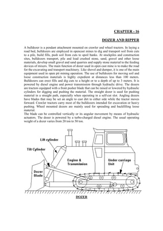
  • 1. CHAPTER - 16 DOZER AND RIPPER A bulldozer is a pendant attachment mounted on crawler and wheel tractors. In laying a road bed, bulldozers are employed in opencast mines to dig and transport soil from cuts to a pile, build fills, push soil from cuts to spoil banks. At stockpiles and construction sites, bulldozers transport, pile and load crushed stone, sand, gravel and other loose materials, develop small gravel and sand quarries and supply stone material to the feeding devices of mixers. The main function of dozer used in open cast mine is to make the road for the excavating and transport machinery. Like shovel and dumper, it is one of the main equipment used in open pit mining operation. The use of bulldozers for moving soil and loose construction materials is highly expedient at distances less than 100 meters. Bulldozers can erect fills and dig cuts to a height or to a depth of up to 3 meters. It is powered by diesel engine and power transmission through hydraulic drive. The dozers are tractors equipped with a front pusher blade that can be raised or lowered by hydraulic cylinders for digging and pushing the material. The straight dozer is used for pushing material in a straight path, especially when operating in a self-cut slot. Angling dozers have blades that may be set an angle to cast dirt to either side while the tractor moves forward. Crawler tractors carry most of the bulldozers intended for excavation or heavy pushing. Wheel mounted dozers are mainly used for spreading and backfilling loose material. The blade can be controlled vertically or its angular movement by means of hydraulic actuators. The dozer is powered by a turbo-charged diesel engine. The usual operating weight of a dozer varies from 20 ton to 50 ton. DOZER
  • 2. Dozer classification The dozers which are commonly used in open pit mining operation are the following types: 1. Straight dozer or bull dozer, 2. Angle dozer, 3. Tilt dozer Straight dozer is the conventional dozer with a cutting edge and blade at right angle to the longitudinal axis of the dozer. The blade can be raised, lowered and tilted slightly but cannot be angled to the direction of travel. This type of dozer is used for pushing the material in a straight path, specially when operating in a self-cut slot. In an angle dozer, the blade can be turned at an angle to the direction of travel as shown in figure. Hydraulic cylinders generally activate the blade. A particularly important feature is that it can throw off a window on one edge of the blade, a feature required for grading haul roads. It is also useful in cutting away the toes of earth embankments or making hillside cuts. The blade is wider than a straight dozer to enable it to cut a full width path when angled. The bottom of the moldboard and the edge are flared out at the lower corners so as to make a full, sharp edged cut when side casting. This causes some undercutting of edges in straight work. The angled position of the blade add a sideward movement of the load to the forward motion which can be utilized in leveling and changing slopes whose is across the path of the machine, in crowning roads, in side casting earth back into small trenches, and in making shallow ditches. The tilt dozer is the modification of straight dozer which has a blade that can be pitched through vertical arc of a few degrees when top of the blade is pitched to the rear. It cuts better for hard material. The push dozer has a blade that has been reinforced at the center with heavy steel plate. The shape and size of the blade is such that it can make contact with the rear end of a scraper. The primary purpose of the push dozer is to make contact with the scraper push back so as to combine its drawbar pull with that of the scraper to speed up the loading of the scraper. The U-bladed dozer has the sides advanced farther than the center. This makes it possible to transport large load by reducing the side spill. The pointed corner assists penetration in hard soil and under stumps and boulders. The dozer may be wheel mounted and crawler mounted. However, crawler mounted dozer is mostly used. The main components of dozer are blade, arms, undercarriage unit, transmission system and blade operation system. The blade has a rectangular base and the back structure with a knife-edge riveted to the bottom part. The body is steel structure and edge that is projected ahead is made of hard steel. The dimensions of the blade may be 4260  1060 mm, 3460  1280 mm. etc. The edge is usually three pieces, a wide center and two corners, which are bolted or riveted. They are of reversible type. The front of the blade is called moldboard and is concave and sloped back. As the blade is pushed into the ground, the knife edge normally cuts and breaks up the dirt that is pushed up the curve of the moldboard until it falls forward.
  • 3. The material being pushed ahead of the blade is thus kept more or less in rotary movement, which tends to even up the load and offer less friction and larger load than would be obtained with the flat vertical moldboard (Fig. a). If the profile blade is incorrectly selected, then, as the dragging prism is being formed, the cut-off soil does not move upwards over the blade surface, but budges the soil mass that forms the dragging prism (Fig. b). This causes the intensive friction between the soil particles. The corner pieces of the blade wear fastest and are sometimes built up by welding until whole edge is so worn as to need reversing or replacing. The rams provided with the dozer are of two types Push arm and Pitch arm. The push arms are heavy, hollow beams extending from a hinged connection with the tractor to the bottom of the blade. The pitch arm helps in controlling the pitch and tilts the dozer blade. The pitch arms are diagonal braces between the push arm and the top of the blade. They brace the blade against loads above the line of the push arms and provide means of regulating the pitch and the tilt of the blade. They may be single piece or two-piece members. Two-piece members help in lengthening or shortening the pitch arm, thereby helping in forward or backward tipping.
  • 4. Dozer blade capacity = 0.5  h2  l  w Where h is the height of the blade, l is the length and w is the specific weight of the material. One level or horizontal ground 20% center bulging is found hence the capacity of the dozer blade is 0.6  h2  l  w. The capacity of a bulldozer depends on the blade shape, distance through which the cut-off material is moved, properties of the material, downgrade or upgrade earth moving. The blade generally pushes 4% more for each percent of down slope as found in actual practice on a level floor. Therefore, on 25% grade, the machine pushes almost double the amount of its normal load on the ground. While in uphill, a half load in comparison with load on level ground is pushed up in a 20% grade and one-fourth of the load is pushed in a 100% grade. This is mainly to counteract the extra load due to gradient effect (W sin ) where,  is the gradient. That is why it is required to operated a bulldozer with variable depth of penetration, beginning with the a depth of 25 – 30% more than that at the end of the pass. The dragging prism forms over 5 – 7m of distance covered. The soil is usually cut off in the first or second gear and moved in the third gear
  • 5. Undercarriage Unit Figure shows a sketch of the undercarriage unit of a dozer. It consists of two units mounted on the main frame. The driving sprocket is fitted at the rear end while the idler wheel is fixed at the front end of the machine.
  • 6. Undercarriage Unit of Dozer An endless chain passes over the sprocket and the idler wheel. The track pads which are usually elevated grouser pads fastened on the track chain. The track chain is driven by the driving sprocket. The track chain is supported in between the carrier rollers and the track rollers which are supported on the bearings mounted on the track frame. The tension adjusting arrangement is fitted between the crawler frame and the idler wheel to adjust the chain sag. Technical description (with hydrostatic drive unit of dozer) A. Make & Model – LIEBHERR 751 / France Engine: Water cooled Cummins Diesel Engine, 295 kW at 1800 rpm Engine starting: 24 V dc, electrical system, starter 1 kW, Alternator 50 amps Attachment Hydraulics: One double gear pump for operation of front and rear mounted attachments. Maximum pump capacity – 72 GPM, 160 bar. Travel drive: Hydrostatic drive. Each track is driven by one variable displacement swashplate type pump and two variable displacement motors. Maxm. pump capacity – 116 GPM, 420 bar Travel speed – 0 to 9.5 kmph, infinitely variable, forward and reverse. Maximum drawbar pull – 530 kN, at 1 kmph Engine speed sensing horsepower control system endures a constant balance between traction and travel speed, guaranteeing full utilization of engine output and engine overload does not occur. Oscillation of track roller frame is  3.50. & track rollers and 2 carrier rollers.
  • 7. Track adjustment by grease cylinder. Automatic parking brake application. B. Make and Model: Hitachi / Japan; FD 30 C (hydrodynamic drive unit of dozer) Engine: 257 kW Electrical System: 24 V, 4 Nos. of batteries, Alternator capacity 55 A Torque Converter: Type: Single stage Torque Multiplication: 2.3 : 1.0 Power shift Transmission: Full power shift, countershaft, constant mesh 3 forward and 3 reverse speed 4.30 kmph (min.) and 12.10 kmph (max.) Steering: Hydraulically released, spring applied, oil cooled, multidisc clutches. Braking: Hydraulically released, spring applied, contracting band oil bath type, service brake Parking Brake Automatic actuation on service brakes with safety transmission lever in lock position or with engine stop. Final Drive: Double reduction 9.30 : 1.0 Undercarriage Unit Hydraulic track adjusters, Sprockets with bolt on segments. Length on track on ground: 3150 mm Gauge: 2135 mm Ground clearance: 510 mm Track rollers: 7 nos. Carrier rollers: 2 nos. Number of shoes per track: 41 nos. Track shoes: 610 mm Ground contact area of track shoes: 38430 cm2 Hydraulic System: Pump: Gear Type, two section Large section 346 lpm Power assist section 27 lpm Relief valve pressure 160 bar Actuation: Single lever, power assisted blade control Hydraulic Tank capacity: 180 litre Blade Size: (Width × Height) 3975 mm × 1650 mm Blade capacity: 8.70 m3 Maximum tilt: 900 mm Maximum pitch: 100 Digging depth: 535 mm
  • 8. Brake Hydraulic system of dozer The Brake Hydraulic Circuit diagram of the dozer Model BD-355A is shown in Figure. Fig. Brake Hydraulic Circuit Diagram The steering gear pump driven by the prime mover of the dozer through its PTO drive unit supplies pressurized hydraulic fluid to the steering and braking system of the dozer. Through flow divider the oil is usually divided into 2 : 1 ratio to the steering and the braking systems of the dozer (for example in dozer model BD-355A, the 141 lpm oil is supplied to the steering system; whereas 70.50 lpm is supplied to the braking system). With the actuation of the brake pedal valve, the oil is directed to the brake booster cylinder that actuates the steering brakes of the dozer. The oil flow from the flow divider for the steering circuit is supplied for the actuation of the steering clutches. The hydraulic circuit diagram of the steering system of the dozer is shown in Figure.
  • 9. Fig. Steering Hydraulic Circuit Diagram Blade control Hydraulic system The dozer blade and the ripper tool are controlled hydraulically. The pump driven by the prime mover through the PTO drive of the transmission unit is installed inside the hydraulic tank. It supplies pressurised hydraulic fluid for the operation of the blade in different position: lift, lower, float and hold. The blade is also tilted hydraulically. Fig. Blade Control Hydraulic System
  • 10. The pressurized oil supplied from the main pump is to the respective control valve after passing through the check valve that serves to check the backflow of the oil. The suction valves are provided to make-up oil from the hydraulic tank for the purpose of filling up oil in the hydraulic cylinders operating the blade and ripper tool of the dozer. During float position the piston is lowered by the self weight of the blade / ripper tool and therefore, vacuum is created in the upper chamber of the respective cylinders. In such case the suction valve draws oil from the hydraulic tank and fills up the void created inside the cylinder. The quick drop valve prevents the free fall of the blade in its downward movement by creating back pressure. The pumps and the control valves are located within the oil tank. The oil filter is located at the top of the tank. A small transmission pump is also driven the prime mover that supplies pressurized oil for the pilot circuit of the control valves as well as to the transmission circuit. Power Transmission System Figure shows the power transmission system of a dozer. The power delivered by the engine is distributed for the propel operation and to drive the auxiliary drive unit. For propel operation of the machine, the power from the hydraulic transmission system (usually a power shift transmission unit) is transferred to the intermediate gear box. The intermediate gear unit has two output shafts which are connected with the drive sprockets through steering clutches and final drive unit (a planetary reduction gear unit). Fig. Power Transmission system of Dozer
  • 11. The steering pump and the transmission pumps are driven through auxiliary drive unit of the power shift transmission. The steering pump supplies pressurized hydraulic fluid for the actuation of the steering clutches and the brake unit of the final drive assemblies; whereas the transmission pump delivers pressurized oil for the actuation of the clutches of the transmission unit. The dozer is steered by controlling the steering clutches individually. During the straight travel of the machine, both the steering clutches are engaged; while the clutches at the left or right are engaged or disengaged accordingly to turn left or right. Bulldozer Operation Digging: As bulldozer movers forward and digs, some of the solid cut by the blade will pile up in front of the blade and move with it, and some of it will drift off the sides, forming ridges and windrows. The dozer digs and transports much more effectively downhill than on a level or uphill, and work should be arranged to work down a grade when it can be done. Breaking piles: A pile of dirt may be knocked down by walking into it with the blade at the desired grade, after which it is spread or piled elsewhere. If the heap is too large or hard for the machine to take it at one pass, or if it is to be preferred in more than one direction, the first part may be made to cut away part of the pile to grade. If the pile is very large or hard in proportion to the power of the dozer, the side cut should be repeated from different angles. Transporting: While transporting the material, the dirt which flows off the sides of the blade must be checked or replaced to keep a full load. If the ground is smooth, the blade is held to just touch it or dig slightly. If the gerund is uneven, an effort is made to cut enough in humps to replace the dirt that is lost in the hollows or drifts off the sides. Spreading: When spreading material, the blade is held somewhat above the original surface so that the dirt can slip under it in a smooth layer on which the machine can work. A thin layer may be spread to the desired grade, but a thick layer should be built higher to allow for compaction. Backblading: After an area has been graded, it may look a bit rough because of small windrows of loose dirt, grouser prints, and piles left where the dozer turned. These may be smoothened down by backing over the area with the blade floating. It acts as drag, smoothing off humps and filling hollows, but does not move enough dirt to change the grade. Inspection Before Starting a Dozer a. Walk around the machine and check for any trace of oil or water leakage. Examine the connections of the high pressure hoses. b. Check tightness of the bolts and nuts. c. Check the engine air cleaner, muffler and track roller supports. d. Check for damaged electric wires.
  • 12. e. Check fuel level, water level, oil levels in the machine. f. Check for the proper functioning of the brakes and the levers.. Procedure for stopping a dozer a. Cool engine gradually by running it at idling speed for about five to ten minutes. b. Cut-off the fuel supply of the engine. c. Turn the starting switch key to the off position and remove key. Precautions for operation of a dozer a. Avoid turning the machine on a slope since the machine tends to slip sideways. b. Always stop the machine on a flat and stable ground. c. If the temperature of oil in torque converter exceeds the limit, the load on the machine to be reduced and wait for the temperature to decrease. d. Never step on the decelerator pedal when going uphill as the engine speed will decrease and climbing ability will be reduced. Component wise Maintenance of Dozer Blade and Arms a. Any material sticking on the front wall should be scraped off. b. The edge of the blade should be inspected for its sharpness. c. Corner pieces should be secured properly. d. Hinge points of both the pitch arms and the push arms should be inspected for any play and then to be lubricated properly. Blade operation control unit a. Inspect for any leakage of hydraulic oil from the hoses and oil seals in blade actuating cylinders. b. Inspect for the smooth operation of the blade lifting cylinders. c. Inspect the operation of the safety valve and locking valve etc. d. Clean and replace the oil strainers. Transmission system a. Operate the main clutch for the proper functioning. b. Inspect the intermediate brake by applying it. c. Oil level in the transmission to be checked. d. Functioning of the steering clutches to be checked. e. Driving sprockets to be checked. Undercarriage Unit a. The shoe and its profile to be checked. b. Excessive sagging of the chain should be corrected by providing proper tensioning. c. Inspect the conditions of the track and the carrier rollers. d. Tighten different mountings and the bolts. Ripper The main function of the ripper is to loosen the rock. This is necessary for stiff clay, semi consolidated sand and gravel etc. which needs to be loaded/transported by
  • 13. scrapper or dozer. Production Ripping is being used more and more today as an alternative to drilling and blasting with explosive. Due to the increased environmental pressures and technological developments, there is tremendous improvements in ripping applications into conditions which formerly required blasting. The material condition of rock affects its rippability. Although sedimentary formations generally offer the best opportunity for ripping and igneous and metamorphic the least, decomposed granites and other weathered igneous and metamorphic rocks often can be ripped economically. The ripper tool is fitted as an additional attachment at the rear end of the dozer or tractor. The hydraulic cylinders control the movement of the ripper tool. It may be required to loose the dense rock with multi-tooth ripper (4 to 5) to raise the output. The loosening (rippebility) of the rock depends on the direction of ripping with respect to the system of joints. Ripping at right angles to the direction of main jointing proves to be most effective. When laminated igneous or metamorphic rocks are ripped, the initial penetration of the tooth into the ground is very important. To facilitate penetration by carrying multiple passes of the ripper or by blasting, an advanced cut of the required depth is made at right angles to the contemplated parallel passes of the rippers. The length of the cut usually varies from 100 m to 200m. Ripper Tool Mainly two types of Ripper tool are used: a. Hinge Type b. Parallelogram Type Each type has special advantage for certain application. Hinge type is used in slabby material with layers and intermittent ripping jobs. In the hinge type the linkage arrangement swings the clevis and shank down through an arc, changing the point angle at various depths. This type offers penetration in the curve and shortens tip and shank life. In parallelogram rippers have a rigid mounting with the dozer. The angle remains constant at any depth and the fixed shank mounting does not allow lateral shank movement. The hydraulic cylinders form the part of the linkage and they can be adjusted to change the ripping angle for the best result in different types of material. The depth of ripping with trailed ripper is normally 0.40 m to 0.50 m, and with self-propelled ripper it is about 1.0 m to 1.5 m, though it depends on the type of soil on which the ripper works. 1. Hinge type – In this type of ripper, the linkage carries the beam and shank pivots about a fixed point at the rear end of the tractor. The shank is also fixed to the linkage at a certain angle. As the shank enters the ground, it penetrates to a depth; the tooth angle is constantly changing. The hinge type ripper uses a beam capable of holding from one to five shanks. The shanks can be adjusted to meet the depth and tooth angle requirements by using a series of holes in the shanks.
  • 14. Tip angle θ = 200 to 300 Clearance angle φ ≥ 80 to 100 Ripping angle γ = 400 to 600 Smaller φ causes crushing of the rock by its base face of the tip, increases its wear and resistance of the rock to ripping. The cutting force of the ripper depends on the ripping angle. Parallelogram Type Ripper Make Model: LIEBHERR 751 / France D – Ground clearance below tool beam – 256 mm H – Maxm. Clearance under tip – 1100mm K – Maxm. Penetration – 1760 mm M – Overall length raised position – 2210 mm N – Overall length lowered position – 2560 mm X - Slope angle – 33.50
  • 15. Y – Shank adjustment angle – 33.50 G - Overall beam width - 1370 mm Parallelogram Ripper with hydraulic pitch adjustment Weight of the Ripper complete unit - 6.1 tonne Ripper: Make and Model: Hitachi / Japan; VP 30 MH / 3 Type: Parallelogram, Variable pitch Ripping depth: 750 mm Ripping width: 2400 mm Shanks: 3 nos. Clearance under tooth with ripper raised: 1750 mm 2. Parallelogram type: - This allows the linkage carrying the beam and shank to maintain an essentially constant tip ground angle regardless of tooth type. Here depth of cut is more. 3. Adjustable Radial ripper type - It combines the features of hinge type ripper with the advantage of shank adjustment capability. Such ripper provides a greater range of shank angles and more reach. It automatically provides more penetration shank angle at the ground entry and after penetration a more optimum angle for advancement through the material. It has the features of both hinge type and parallelogram type. It can vary the tip angle with respect to vertical for improved penetration and can be hydraulically adjusted while ripping to provide optimum ripping angle in most of the material. The impact ripper is mounted to the tractor on a multi shank adjustable parallelogram frame. It incorporates a hydraulic hammer. The tractor of the dozer provides the hammer power. The hammer strikes the shank assembly which transmits the hammer force in to ripping force. These combined with the draw bar pull provides the material penetration and material sizing capabilities greatly increased over conventional ripping. Advantage is that there is no noise pollution, no dust, big size of boulders is not there and the secondary operation is not required. Working on rock requires narrow shoe to reduce bending or breakage. This should be the single grouser shoe heat treated to a higher tensile strength and it should provide the better wear resistance as compared to normal conventional track shoe. The short teeth should be used in extreme impact conditions. The intermediate teeth are to be used for moderate impact and abrasion conditions. The long tip is designed for low impact, highly abrasion conditions where the breakage of rock is not a problem. The shank protector is a replaceable item which is pinned to the leading edge of the shank, protecting it from wear and greatly extending the shank life. Ripper shanks are generally available in two basic designs. One is straight another is curved. Straight shank provides the lifting action needed in tight, laminated materials plus the ripping ability required in blocky or shabby material. On the other hand, the curved shanks work well in less dense material and also produce less ripping resistance. The cost of ripping depends on what method should be used to get the solid material into movable form. The advantage of the large ripping tractor over the drilling and
  • 16. blasting is its ability to loose more materials faster and at a lower cost per m. About 30 to 40% of ripping cost is the cost of its tool. Attachment of Multi-Shank Ripper with Dozer 1. Main control valve, 2. Divider block, 3. Ripper tilt cylinder (right) 4. Ripper lift cylinder (right), 5. Ripper lift cylinder (left), 6. Ripper tilt cylinder (left) Example: A dozer blade has the dimension of 4500 mm  2000 mm operates on level ground. What will be the output capacity of the dozer ? Solution With reference to the figure, The output of the dozer blade = 0.5  h2  L = 0.5  2  2  4.5 = 9.0 m3 Considering 20% of the bulging of the material in front of the blade The output of the dozer blade = 9  1.2 = 10.8 m3 Ans.