Panasonic AV-HS410 Multiformat Vision Mixer HD/SD
•
1 j'aime•743 vues

The AV-HS410 is a live production switcher that provides: 1) High-end performance and functions in a compact body, including 9 video inputs, 6 outputs, chroma keying, transitions, and memory functions. 2) An intuitive user interface designed for live operation, with a built-in LCD monitor, memory preview, and multi-viewer display. 3) Expandability through optional input/output boards and a software development kit to add customized functions.

Recommandé
Contenu connexe
Tendances
Tendances (17)
En vedette
En vedette (20)
Similaire à Panasonic AV-HS410 Multiformat Vision Mixer HD/SD
Similaire à Panasonic AV-HS410 Multiformat Vision Mixer HD/SD (20)
Plus de AV ProfShop
Plus de AV ProfShop (20)
Dernier
Dernier (20)
Panasonic AV-HS410 Multiformat Vision Mixer HD/SD
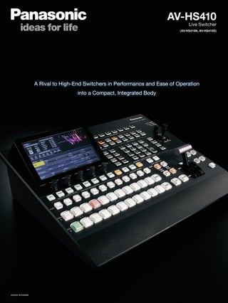
- 1. AV-HS410 Live Switcher (AV-HS410N, AV-HS410E) A Rival to High-End Switchers in Performance and Ease of Operation into a Compact, Integrated Body picture simulated
- 2. High-End Performance and Functions in a Compact Body. A User Interface Designed for Live Operation, and Plug-in Compatibility for Easy Expansion. ● Nine Standard Inputs: Eight SDI and One DVI Six Standard Outputs: Five SDI and One DVI Optional: Additional Four inputs/Four outputs maximum ● Built-in 178 mm (7 inches) multi-mode color LCD monitor displays versatile menus, image monitor, waveform/vectorscope, etc. ● Featuring High-quality Primatte® chroma keying and Versatile transitions, including DVE functions ● Enhanced MultiViewer Display with up to 16 splits enables nine screen variations, clock, level meter and 4:3 marker display. ● Video Memory function allows playback of two channels of still or moving images. ● Memory Preview function provides previews of shot memory and event memory image effects. ● Supports Plug-in API function for external control, external camera control, output of status data, etc. ● Control panel with additional direct button control, numeric keypad, etc achieves enhanced ease of operation. * Primatte® is a registered trademark of IMAGICA DIGIX Inc. The copyrights of Primatte® belong to IMAGICA DIGIX Inc. The patents for Primatte® belong to IMAGICA DIGIX Inc. picture simulated
- 3. Input/Output Signal Standard Option Board AV-HS 04M1 AV-HS 04M2 AV-HS 04M3 AV-HS 04M4 AV-HS 04M5 AV-HS 04M6 AV-HS 04M7 AV-HS 04M8 Video Signal Video Format SDI x 8 DVI-D x 1 SDI x 5 DVI-D x 1 SDI x 2 COMP x 2 DVI-I x 2 COMP x 2 DVI-I/ COMP VIDEO x 2 SDI x 2 DVI-D x 2 IN IN OUT OUT IN IN IN OUT OUT IN OUT IN SDI 480/59.94i √ √ √ √ 576/50i √ √ √ √ 1080/59.94i √ √ √ √ 1080/50i √ √ √ √ 720/59.94p √ √ √ √ 720/50p √ √ √ √ 1080/24PsF √ √ 1080/23.98PsF √ √ DVI Analog XGA (1024 x 768) 60 Hz/50 Hz √ √ WXGA (1280 x 768) 60 Hz/50 Hz √ √ SXGA (1280 x 1024) 60 Hz/50 Hz √ √ DVI Digital (PC) XGA (1024 x 768) 60 Hz/50 Hz √ √ √ √ √ WXGA (1280 x 768) 60 Hz/50 Hz √ √ √ √ √ SXGA (1280 x 1024) 60 Hz/50 Hz √ √ √ √ √ UXGA (1600 x 1200) 60 Hz/50 Hz √ √ √ √ WSXGA+ (1680 x 1050) 60 Hz/50 Hz √ √ √ √ WUXGA (1920 x 1200) 60 Hz/50 Hz √ √ √ √ DVI Digital (VIDEO) 1080/59.94i √ √ 1080/59.94p √ √ √ 1080/50i √ √ 1080/50p √ √ √ 720/59.94p √ √ 720/50p √ √ Analog Composite NTSC √ PAL √ Analog Component 480/59.94i √ √ √ 576/50i √ √ √ 1080/59.94i √ √ √ 1080/50i √ √ √ 720/59.94p √ √ √ 720/50p √ √ √ Nine Standard Inputs/ Six Standard Outputs (Max. 13 Inputs/10 Outputs) The AV-HS410 comes standard with Nine inputs (Eight SDI (HD/SD) and One DVI-D) and Six outputs (Five SDI (HD/SD) and One DVI-D). Two expansion slots accommodate either input or output optional boards, providing a maximum of 13 inputs, and 10 outputs. HD/SD Multi-Format Support The AV-HS410 supports standard HD/SD multi-format, including 1080/24PsF. System frequency is 59.94 Hz/50 Hz/24 Hz switchable. This makes the system ideal for digital cinema production and worldwide operation. A wide range of optional boards also allows the input and output of analog component and various other signals. (Please see the table at the right for more details.) AV-HS410*1 HD Component IN HD Component IN *Additional application is required for the operation of the system. Please contact your Panasonic representative for more information. RS-422A TALLY/GPIRS-422A DVI-D Output LAN DVI-D IN*2 HD SDI OUT HD SDI OUT HD SDI IN HD SDI IN VTR etc. HDMI OUT DVI-D IN HD Camera Recorder HD Camera Recorder System Camera HD Camera Recorder DVD Player AUX Panel AUX Panel Editing Controller PC HD SDI Monitor PC Monitor, Projector, etc. HD SDI Monitor Remote Camera Switching Hub HDMI/DVI-D Conversion Cable PC *Additional application is required for the operation of the system. Please contact your Panasonic representative for more information. *1: The photo shows a system example with the optional AV-HS04M8 and AV-HS04M2 boards mounted. *2: This connector does not support the HDCP technologies.
- 4. Various Switching Functions and High Image Quality are Achieved with an Intuitive User Interface. Built-in Frame Synchronizer for All Input Channels All input channels feature a built-in frame synchronizer for use in switching unsynchronized video signals. A gen-lock function also supports synchronizing systems based on external sync signals (black burst or tri-level). Up-Converter, Dot by Dot and Video Processing The AV-HS410 is equipped with an SD/HD up-converter function for four inputs, and a dot by dot function for eight inputs. Dot by dot input can be used for P-in-P display of HD images from SD footage without degradation. A video processing function with color correction is also provided for eight inputs. Four Aux Buses and Two P-in-P Two P-in-P buses and four Aux buses are provided. Borders and software effects can be applied to the P-in-P buses. In addition to a Cut transition, the bus transition function (P-in-P bus and Aux bus switching effect) also enables a Mix transition (Aux 1 only). Flexible operation is achieved by combining Aux buses and M/E sections. Versatile Transitions and Effects In addition to standard wipe, mix and cut effects, DVE transition patterns using two channels, such as reduce, slide, squeeze and 3D wipe are included. New Video Memory Function for Two Inputs Two inputs for still (STILL) or moving (CLIP) images can be saved in Video Memory, and selected as bus footage. Moving pictures can be recorded and played with key signals (for a maximum of approximately 20 seconds/600 frames with 59.94i). Moving picture and still files can also be transferred over a LAN network from an SDHC/SD Memory Card or PC. * Uploading of moving picture and still images from an Ethernet LAN will be supported in the future. SDHC/SD Memory Card Slot Video memory, shot memory, event memory and set-up data can be saved to SDHC/SD Memory Cards. Primatte® High-Quality Chroma Key Linear, luminance and chroma keying are provided. Chroma keying employs the Primatte® algorithm, which is widely used as a plug-in for nonlinear editors. The same excellent Primatte® image quality that is used worldwide for movies, TV programs, music videos and commercials is achieved by the AV-HS410's real time processing. Superior blue-spill processing naturally combines translucent objects, such as thin cloth and glass, with background colors. Extremely fine objects, such as individual strands of hair, are faithfully reproduced. One DSK channel is also provided to add borders, shadows, and other edge effects. * Primatte® is a registered trademark of IMAGICA DIGIX Inc. The copyrights of Primatte® belong to IMAGICA DIGIX Inc. The patents for Primatte® belong to IMAGICA DIGIX Inc. Shot Memory Up to 100 image effects, such as background transition patterns, P-in-P sizes and border widths, can be registered in shot memory for instant retrieval. The AV-HS410's Effect Dissolve function enables smooth switching from a current image to one of the images or operations registered in the shot memory. Event Memory Up to 64 of the image effects that are registered in the shot memory can be sequentially registered in the event memory for instant retrieval. This allows highly expressive consecutive effects to be easily and smoothly executed. Up to 100 event memories can be registered. picture simulated Circle wipe Page turn Primatte® chroma key (picture simulated) Conventional chroma key (picture simulated)
- 5. New Memory Preview This new function lets you preview the shot memory and event memory content. It allows image effects to be easily confirmed while on-air with this 1 M/E switcher. This is particularly convenient for live operation. * The resolution of images output from memory is slightly lower than the usual resolution. Built-in 178 mm (7 inches) Color LCD Monitor with Multi-Mode Display A 178 mm (7 inches) color LCD monitor with WVGA (800 x 480) resolution is built into the control panel. It can be switched to a wide variety of display modes, including setting menus, image monitoring and waveform/vectorscope. (See the table above.) It also supports the MultiViewer and Memory Preview functions. AV-HS410 provides comfortable operation eliminating the need to view multiple displays in different locations. Enhanced MultiViewer Display The MultiViewer function lets you split the screen to display PVW, PGM and all source images on a single screen. It enables 4/5/6/9/10/16 split screens. The input signal name, audio level meter and 4:3 marker can also be overlaid onto each screen, and a clock can be displayed. This makes it possible to efficiently operate a multi- channel system with a single monitor. Easy-to-Use Panel Layout Features such as a total of 12 crosspoint buttons in each A bus and B bus (for a maximum of 22 with the Shift function) allow direct control with this simple panel layout. Function settings and registrations are made quickly and intuitively with the LCD monitor's matrix menu and rotary switches. Various functions can also be assigned to eight user buttons for one-touch operation. This level of easy operation supports speed and accuracy in live-relay operation. 4 Split 5 Split "A" 5 Split "B" 9 Split6 Split "B" 10 Split "B" 16 Split 6 Split "A" 10 Split "A" 1 2 3 4 1 2 3 4 5 4 5 1 2 3 1 2 3 4 5 6 7 8 9 4 5 6 1 3 42 9 10 1 3 42 5 7 86 1 3 42 5 7 86 9 11 1210 13 15 1614 3 5 6 1 4 2 3 5 64 7 9 108 1 2 Shot Memory Event Memory Memory Preview Bus Access Program Bus Program Image Preview Image Mode: PGM Output: PGM Mode: MEM-PVW Output: MEM-PVW Assign of cross point One line of menu display on a image monitorMenu display/Subscreen/Image displayMenu display in Matrix type VECTOR displayWFM display
- 6. Expanded Functions with Plug-in Software and Optional Boards Plug-in Software Created with a Software Development Kit* Plug-ins allow flexible expansion of software-based functions. A Software Development Kit (SDK) is provided so that third parties or SI enterprises can freely develop the software to add new functions to the AV-HS410. This will enable the system to meet an even wider range of needs, such as controlling the AV-HS410 with an external controller or PC, operating cameras and other devices from the AV-HS410, and outputting status data related to the live switcher or image sources. * Please ask your dealer for details. *1: When external synchronization is selected as the reference signal setting, the reference signal is input. When internal synchronization is selected, the reference signal is output. *2: When external synchronization is selected as the reference signal setting, the signals are looped through output. When internal synchronization is selected, the reference signal is output. *3: Two sets of the same output signals are distributed from SDI OUTPUT 1. *4: Use a crossover cable when connecting the unit and another device on a 1:1 basis without going through a switching hub. *5: Use a switching hub. Input Option Boards (As of December, 2011) Output Option Boards (As of December, 2011) AV-HS04M2 Analog Component Input Board HD/SD Analog Component x 2 (Y/PB/PR) (Built-in Up-converter) AV-HS04M3 DVI Input Board DVI-I x 2 (Built-in Scaler) AV-HS04M4 Analog Output Board HD/SD Analog Component x 2 (Y/PB/PR) AV-HS04M5 DVI/Analog Output Board DVI-I×1, HD/SD Analog Component x 1 (Y/PB/PR) AV-HS04M6 Analog Composite Input Board Analog Composite x 2 (Built-in Up-converter) AV-HS04M7 SDI Output Board SDI (HD/SD) x 2 (Each one has 2 outputs) (BNC) (Built-in Down-converter) AV-HS04M1 SDI Input Board SDI (HD/SD) x 2 (BNC) (Built-in Up-converter) AV-HS04M8 Full HD DVI Input Board DVI-D x 2 (compatible with WUXGA) SDI Input 1 to 8 Memory card Input A1, A2 Input B1, B2 Output A1, A2 Output B1, B2 Black STILL1, 2 CLIP1, 2 Input matrix ColorBar Color BKGD1, 2 Output matrix SDI Output 1-1, 1-2 ( 3) SDI Output 2 to 5 DVI-D Output ~ AC IN PowerAC/DC SDI OUTPUT 1-1, 1-2 SDI OUTPUT 2 to 5 DVI-D OUT ScalerDVI-D Input SDI IN 5 to 8 FS UC VPrc DbyD SDI IN 1 to 4 FS VPrc DbyD DVI-D IN Scaler BKGD CUT, MIX, WIPE, DVE KEY CUT, MIX, WIPE, DVE AUX 1 to 4 WFM MEM PVW FTB Multi View DSK CUT, MIX PinP1, 2 CUT, MIX Option slot A Option slot B REF IN/OUT ( 1) REF OUT ( 2) Reference signal TALLY/GPI 1 Dsub 15 GPI-IN: 8 GPI-OUT: 19 ALARM OUT: 1 GND: 2 TALLY/GPI 2 Dsub 15 Editing controller Aux panel VTR, etc. Switching hub COM Dsub 9 EDITOR Dsub 9 LAN RJ45 Remote cameraAux panelComputer ( 4) ( 5) Block Diagram
- 7. Specifications (As of December, 2011) Power Requirement: AC 100 V to 240 V, 50 Hz/60 Hz, 88 W Operating Temperature: 0 °C to 40 °C (32 °F to 104 °F) Operating Humidity: 10 % to 90 % (no condensation) Dimensions: 440 mm x 158 mm x 361 mm (W x H x D) (17-5/16 inches x 6-7/32 inches x 14-7/32 inches) excluding protrusions Weight: Approx. 6.2 kg (13.669 lb) excluding accessory parts when no options have been installed Approx. 6.6 kg (14.550 lb) excluding accessory parts when all the possible options have been installed Video Inputs (13 signal lines maximum): Standard SDI: 8 signal lines, BNC x 8 (SDI INPUT 1 to SDI INPUT 8) (The up-converter function can be used for the SDI INPUT 5 to SDI INPUT 8 connectors.) Standard DVI-D: 1 signal line, DVI-D x 1 Optional: Up to 4 additional signal lines (IN A1, IN A2, IN B1, IN B2) (Up to two option boards can be installed in the two input/output slots.) Video Outputs (10 signal lines, maximum): Standard SDI: 5 signal lines, BNC x 6 (SDI OUTPUT 1 to SDI OUTPUT 5 x 1 line each, 2 distributed outputs for SDI OUTPUT 1 only) Standard DVI-D: 1 signal line, DVI-D x 1 Optional: Up to 4 additional lines (OUT A1, OUT A2, OUT B1, OUT B2) • PGM, PVW, AUX1 to AUX4, MV (MULTI_VIEW), CLN, KEYOUT and MEM PVW can be assigned to SDI OUTPUT 1 to SDI OUTPUT 5, DVI-D OUT, OUT A1, OUT A2, OUT B1 and OUT B2. • CLN can be pre-selected from KEY or DSK using a menu. (Up to two option boards can be installed in the two input/output slots.) Signal Formats: SD: 480/59.94i, 576/50i HD: 1080/59.94i, 1080/50i, 720/59.94p, 720/50p, 1080/24PsF*, 1080/23.98PsF* *The following option boards are not supported: AV-HS04M1, AV-HS04M2, AV-HS04M3, AV-HS04M4, AV-HS04M5, AV-HS04M6, AV-HS04M7 Signal Processing: Y: PB: PR 4: 2: 2, 10 bit (8 bit for video memory), RGB 4:4:4, 8 bit ME Number: 1 ME SDI Inputs: HD-SDI: HD Serial digital (SMPTE 292M) SD-SDI: SD Serial digital (SMPTE 259M) 8 signal lines, standard: IN1 to IN8 12 signal lines, maximum: IN A1, IN A2, IN B1, IN B2 (When two AV-HS04M1 boards are used; with active through) HD: SMPTE 292M (BTA S-004B) standard complied with • 0.8 V [p-p] ±10 % (75 Ω) • Automatic equalizer More than 100 m (328 ft) (when 1.5 Gbps/5C-FB cable is used) SD: SMPTE 259M standard complied with • 0.8 V [p-p] ±10 % (75 Ω) • Automatic equalizer 200 m (656 ft) (when 5C-2V cable is used) SDI Outputs: HD-SDI: HD Serial digital (SMPTE 292M) SD-SDI: SD Serial digital (SMPTE 259M) 5 signal lines, standard: OUT1 x 2; OUT2 to OUT5 x 1 each 9 signal lines, maximum: OUT A1, OUT A2, OUT B1, OUT B2 (When two AV-HS04M7 boards are used) HD: SMPTE 292M (BTA S-004B) standard complied with • Output level 0.8 V [p-p] ± 10 % • Rise time HD: Less than 270 ps • Fall time HD: Less than 270 ps • Difference between rise time and fall time HD: Less than 100 ps • Alignment jitter HD: Less than 0.2 UI (130 ps) • Timing jitter HD: Less than 1.0 UI • Eye aperture ratio More than 90 % • DC offset 0 ±0.5 V SD: SMPTE 259M standard complied with • Output level 0.8 V [p-p] ±10 % • Rise time Less than 1.5 ns • Fall time Less than 1.5 ns • Difference between rise time and fall time Less than 0.5 ns • Jitter Less than 0.2 UI Composite Input: Analog composite signal (NTSC/PAL) (1.0 V [p-p], 75 Ω) (Option board) 4 signal lines, maximum: IN A1, IN A2, IN B1, IN B2 (When two AV-HS04M6 boards are used; with loop-through) Analog Input: SD/HD analog component Y/PB/PR (1.0 V [p-p], 75 Ω) (Option board) 4 signal lines, maximum: IN A1, IN A2, IN B1, IN B2 (When two AV-HS04M2 boards are used) Analog Output: SD/HD analog component Y/PB/PR (1.0 V [p-p], 75 Ω) (Option board) 4 signal lines, maximum: OUT A1, OUT A2, OUT B1, OUT B2 (When two AV-HS04M4 boards are used) • 2 signal lines (OUT A1, OUT B1) when two AV-HS04M5 boards are used. DVI-I Input: Analog/digital RGB: (Option board) XGA (1024 x 768), WXGA (1280 x 768), SXGA (1280 x 1024) Vertical frequency: 60 Hz • This connector does not support the HDCP technologies. 4 signal lines, maximum: IN A1, IN A2, IN B1, IN B2 (When two AV-HS04M3 boards are used) DVI-I Output: Analog/digital RGB: (Option board) XGA (1024 x 768), WXGA (1280 x 768), SXGA (1280 x 1024), WSXGA+* (1680 x 1050), UXGA* (1600 x 1200), WUXGA* (1920 x 1200) * Selectable only when digital signals are output. Vertical frequency: 60 Hz • This connector does not support the HDCP technologies. 2 signal lines, maximum: OUT A2, OUT B2 (When two AV-HS04M5 boards are used) DVI-D Input: Digital RGB: (Option board) XGA (1024 x 768), WXGA (1280 x 768), SXGA (1280 x 1024), WSXGA+ (1680 x 1050), UXGA (1600 x 1200), WUXGA (1920 x 1200) Vertical frequency: 60 Hz Digital RGB: 1080/50p, 1080/59.94p • Analog input signals are not supported. • This connector does not support the HDCP technologies. 4 signal lines, maximum: IN A1, IN A2, IN B1, IN B2 (When two AV-HS04M8 boards are used) • The DVI-I connector cable cannot be used. • For the DVI-D connector cable, use a cable with a length of up to 5 m (16.4 ft). DVI-D Input/Output: Digital RGB: XGA (1024 x 768), WXGA (1280 x 768), SXGA (1280 x 1024), WSXGA+ (1680 x 1050), UXGA (1600 x 1200), WUXGA (1920 x 1200) Vertical frequency: 60 Hz Video format inputs: Digital RGB: 1080/50p, 1080/59.94p Vertical frequency: Same as system formats Video format outputs: Digital RGB: 1080/50p, 1080/59.94p, 1080/50i, 1080/59.94i, 720/50p, 720/59.94p • The input and output of analog signals are not supported. • Output support the high-resolution multi view mode: Signals are output with a high resolution even when SD is set as the system mode. (When high-resolution multi view mode has been enabled, MV is selected as the DVI-D OUT output, and it is not possible to select MV with SDI OUT.) • This connector does not support the HDCP technologies. Standard input/output: 1 line each (DVI-D IN, DVI-D OUT) • The DVI-I connector cable cannot be used. • For the DVI-D connector cable, use a cable with a length of up to 5 m (16.4 ft). Reference In GENLOCK mode: Black burst or Tri-level Sync input signals Input/Output: (with loop-through) In internal sync mode: Black burst output signals x 2 • Same field frequencies as those of the system formats supported. • With the 1080/24PsF format, only GENLOCK mode supported. • With the 1080/23.98PsF format, black burst with 10F-ID (SMPTE318M standard met) or TRI signals supported. Video Delay Time: 1 line (H), When the frame synchronizer setting is “Off” and the up-converter setting is “Off”. 1 frame (F), When the frame synchronizer setting is “On” or the up-converter setting is “On”. • When the signals have passed through PinP, DVE, multi view, down-converter, DVI-IN or DVI-OUT, a maximum delay of 1 frame is applied in each case. Control I/O (LAN): RJ-45 LAN 10BASE-T/100BASE-TX (For IP control) Connecting cable: LAN cable (category 5 or above), max. 100 m [328 ft], STP (Shielded Twisted Pair) cable recommended • When connecting to a hub (switching hub), use a straight cable. Use a crossover cable when connecting the unit and computer on a 1:1 basis without going through a hub. • Use with the same segment is recommended for the equipment which is connected to the unit. If the unit is connected to equipment whose segments are different, events dependent upon the settings inherent to the network equipment, for instance, may occur so thoroughly check the connections with the equipment to which the unit will be connected prior to the start of operation. Control I/O (EDITOR): D-sub, 9-pin, female EDITOR Used to control an editor RS-422 control connector Communication format Baud rate: 38400 bps, Character length: 8 bit, Parity: Odd Stop bit: 1 bit, Flow control: None Control I/O (COM): D-sub, 9-pin, female COM Used to control an external device RS-422 control connector Communication format (selected using a menu) • Mode: 1 (default setting), Baud rate: 9600 bps, Character length: 8 bit Parity: None, Stop bit: 1 bit, Flow control: None • Mode: 2, Baud rate: 38400 bps, Character length: 8 bit, Parity: Odd Stop bit: 1 bit, Flow control: None • Mode: 3, Baud rate: 38400 bps,Character length: 8 bit,Parity: None Stop bit: 1 bit, Flow control: None Control I/O: D-sub, 15-pin, female ( x 2) (TALLY/GPI 1 Input: 8 inputs, general-purpose, photocoupler sensing TALLY/GPI 2) Output: 19 outputs; selected from R/G tally, general-purpose Alarm: 1 output, open collector output (negative logic) Other: BOOT switch [SV/NM (service/normal) ] (for maintenance purposes) Normally, this switch is used as the “NM” position.
- 8. 25K201205ZP-1 Printed in Japan SP-HS410PE2 Panasonic Corporation Business Solutions Business Group 2-15 Matsuba-cho, Kadoma, Osaka 571-8503 Japan http://pro-av.panasonic.net/ Argentina +54 1 308 1610 Australia +61 (0) 2 9491 7400 Bahrain +973 252292 Belgium +32 (0) 2 481 04 57 Brazil +55 11 3889 4035 Canada +1 905 624 5010 China +86 10 6515 8828 Hong Kong +852 2313 0888 Czech Republic +420 236 032 552/511 Denmark +45 43 20 08 57 Egypt +20 2 23938151 Finland, Latvia, Lithuania, Estonia +358 (9) 521 52 53 France +33 (0) 1 47 91 64 00 Germany, Austria, Switzerland +49 (0) 611 235 459 Greece +30 210 96 92 300 Hungary +36 (1) 382 60 60 India +91 120 247 1000 Indonesia +62 21 385 9449 Iran (Vida) +98 21 2271463 (Panasonic Office) +98 2188791102 Italy +39 02 6788 367 Jordan +962 6 5859801 Kazakhstan +7 727 298 0891 Korea +82 2 2106 6641 Kuwait +96 522431385 Lebanon +96 11665557 Malaysia +60 3 7809 7888 Mexico +52 55 5488 1000 Netherlands +31 73 64 02 577 New Zealand +64 9 272 0100 Norway +47 67 91 78 00 Pakistan +92 5370320 (SNT) Palestine +972 2 2988750 Panama +507 229 2955 Peru +51 1 614 0000 Philippines +63 2 633 6163 Poland +48 (22) 338 1100 Portugal +351 21 425 77 04 Puerto Rico +1 787 750 4300 Romania +40 21 211 4855 Russia CIS +7 495 6654205 Saudi Arabia +96 626444072 Singapore +65 6270 0110 Slovak Republic +421 (0) 2 52 92 14 23 Slovenia, Albania, Bulgaria, Serbia, Croatia, Bosnia, Macedonia, Montenegro +36 (1) 382 60 60 South Africa +27 11 3131622 Spain +34 (93) 425 93 00 Sweden +46 (8) 680 26 41 Syria +963 11 2318422/4 Taiwan +886 2 2227 6214 Thailand +66 2 731 8888 Turkey +90 216 578 3700 U.A.E. (for All Middle East) +971 4 8862142 Ukraine +380 44 4903437 U.K. +44(0)1344 70 69 13 U.S.A. +1 877 803 8492 Vietnam +848 38370280 [Countries and Regions] Factories of Business Solutions Business Group have received ISO14001:2004-the Environmental Management System certification. (Except for 3rd party’s peripherals.) 4 INS POWER ALARM LINK Live Switcher AV-HS410 U1 U2 U3 U4 U5 U6 U7 U8 USER BUTTON MENU MODE PICT DSK TIME PLUGIN BKGD CBGD KEY CHRKEY PinP1 PinP2 MENU HOLD XPT MV IN OUT CONFIG SYS MENU OFF WFM VECT VMEM SD Card SHOT EVENT DISPLAY MENU SELECT POSITIONER X/Y Z MENU INPUT VMEM BKGD PATT KEY PATT TAKE ENTER / + PAGE PLAY REC STOP XPT DSBL < CLIP 1 STILL 1 MEMORY / WIPE PATTERN / 10 KEY << TRIM OFF>> CLIP 2 STILL 2 REV TRIM OUT TRIM IN 9 PASTE 6 MOD 3 REV C UNDO 8 COPY 5 DEL 2 > . >> 7 NEW 1 < 0/10 << STORE RE CALL EDIT DEL SHOT MEM EVENT MEM PLUGIN MEM1 PLUGIN MEM2 > F1 F2 F3 F4 F5 AMBER : FILL / GREEN : SOURCE KEY PinP1 PinP2 DSK AUX1 AUX2 AUX3 AUX4 DISP MV AUX BUS DELEGATION PGM A PST B AUX 1/13 2/14 3/15 4/16 5/17 6/18 7/19 8/20 9/21 10/22 11/23 12/24 AUX/DISP SOURCE SHIFT SHIFT SHIFT PGMPVW CUT AUTO MIX MIX WIPE N/R R BKGD KEY KEY ON FTB ON PinP1 ON PinP2 ON DSK ON WIPE DIRECTION WIPE MIX WIPE ON OFF POWER ∼ACIN GND SIGNAL LAN SLOTA IN/OUTA1 IN/OUTA2 IN/OUTB1 IN/OUTB2 SLOTB DVI-DIN DVI-DOUT SVNM 43 SDIOUTPUTS 1 2 587654321 SDIINPUTS EDITORCOMTALLY/GPI2TALLY/GPI1REF BOOT 440 mm (17-5/16 inches) 158 mm (6-7/32 inches) 31 mm (1-7/32 inches) 361mm(14-7/32inches) 120 mm (4-23/32 inches) Dimensions http://pro-av.panasonic.net/Please refer to the latest information, etc. at the following Panasonic web site.