SlideShare une entreprise Scribd logo
1  sur  12
Research on Electronic Control Technology of
Fiber Coupled Laser-Diode
Abstarct: For special power requirements of the laser module, which is consist of the multiple
laser diode(LD) chips series driven and the power of sythetic by combining the fiber, a small
high-efficiency laser current source component is desighed and developd, and a small
high-efficienct semiconductor cooling thermal electrical cooler (TEC) fiber-coupled laser module
temperaturecontrolling comp onenr is presented as well. The component operting temperature
range is from -45℃ to 55℃, and the result that the design can meet the performance
reauirements has been proved in the experiment. The mathematical model of LD established. The
digital design method of a laser current source controlling circuit is presented, and achieved using
ADuC831. The temperature controlling component structure of a LD module based on the TEC is
introduced, a simplified mathermatical model of the temperature control component is
established, and the coefficient of operating current I of TEC are optimized to solve the problem
of laser output wavelngth drifting with temperature.
Keywords: lasers; fiber coupling laser; laser current source; thermal electrial cooler temperature
control; digtial control technology;
1 Introduction
As a new type of light source, semiconductor laser (LD) has been one of the focuses of people
because of its characteristics such as high conversion efficiency, small size, light weight, high
reliability, direct modulation and strong ability to integrate with other semiconductor devices. .
The fiber-coupled output high-power laser diode module has the characteristics of small size,
good beam quality, and high brightness. It can replace the existing YAG solid-state lasers
directly for laser beam guidance, medical treatment, laser processing, photoelectric detection,
and lidar. However, semiconductor lasers have a large wavelength drift with temperature, which
is required to be widely used. The problem of power driving and heat dissipation has always been
that the driving power has a high current stability. To avoid damage to the laser due to
overheating or excessive power consumption, it is required that the power supply is free from
power-on and switch-on current shocks. The power part of the traditional current source circuit
generally adopts a circuit form in which a power amplifier tube and a laser are connected in
series. The advantage of this circuit form is that the circuit is simple, but in order to make the
power amplifier tube have constant current characteristics, it must work in the amplification
region, especially when the current source output current is required to have a large range of
variation, a large Power consumption, generating excessive heat, will reduce power efficiency and
reduce system reliability. Multi-die series-excitation fiber-coupled output semiconductor lasers
can output very high continuous laser power. Since the efficiency of the laser is only 35% to 45%,
for the continuous laser output of more than ten watts, in order to improve the efficiency of the
semiconductor laser current source, it must be used It has high efficiency and low power
consumption PWM type DC / DC conversion circuit as the drive current source of the laser, and
solves the problem of DC / DC conversion circuit control and power-on shock. According to the
application requirements of fiber-coupled lasers, this paper develops an LD module drive current
source and temperaturecontrol circuit system.
2. Basic Principles of Fiber-Coupled Output LD
The principle block diagram of a multi-die series excitation fiber-coupled output semiconductor
laser module is shown in Figure 1. LD1 to LD6 are laser diode units. The light beam emitted by the
LD is first collimated by a micro-cylinder lens. The collimated light beam can be considered as a
linear light source with a certain divergence angle in the y direction. The output beam of ~ LD6 is
reflected twice by mirror 1 and mirror 2, respectively. The propagation direction of the beam is
rotated 180 °, and a group of composite beams are formed. Into a set of parallel line light
sources, each line light source has a certain divergence angle in the x and y directions
(corresponding to the slow axis divergence angle of the laser diode and the fast axis divergence
angle, respectively), using two vertical The placed cylindrical lens 1 and lens 2 can focus and
couple such a composite beam into an optical fiber for power synthesis. The combined beams are
shown as ③ and ④ in the figure. The main technical indicators of the laser drive current
source are: 1) the output current is continuously adjustable from 0 to 4A; 2) the output voltage
varies from 8 to 17V; 3) the relative stability of the output current of the current source is better
than 0.5%; 4) none Current impact; 5) The operating temperature range of the LD module is
-45 ℃ ~ 50 ℃; 6) In order to avoid the laser wavelength of the LD module from drifting too
much with the temperature, the ambient temperature of the LD die is controlled between -5 ℃
and 20 ℃.
3. LD drive current source circuit model
The drive current source circuit model is shown in Figure 2. In the figure, H1 (s) and H2 (s) are the
transfer functions of the control circuit, and H3 (s) is the transfer function of the DC / DC
conversion circuit. The DC / DC conversion circuit consists of a voltage-controlled PWM-type
high-efficiency switching power supply. The output voltage is the output voltage of the drive
current source of the LD module and the relationship between the control voltage Vc is
approximately: V0 = 5Vc + 6, (1) where 0 ≤ Vc ≤2.
Laser diodes are non-linear devices. Their volt-ampere characteristics are similar to those of
diodes. If they are equivalent to linear resistors (RD = VD / ID) near the operating point, VD and ID
are the operating voltage and current of the LD module , Then the transfer function of the
linearized model of the current source circuit shown in Figure 2 can be expressed as: I (s) = H0 (s)
Vs (s) / [RD + Rf + RfH0 (s)], (2) where H0 (s ) = H1 (s) H2 (s) H3 (s).
If the circuit design satisfies | RfH0 (s) |》 RD + Rf, the steady-state current output by the laser
power supply is: I (s) = Vs (s) / Rf. (3)
(3) When the value of H0 (s) is large enough, in the linear region of the DC / DC conversion circuit,
the output steady-state current is independent of the equivalent resistance of the LED module,
that is, the DC / DC module has a constant current output. characteristic. Rf generally takes a
resistance value of 0.01 ~ 0.10Ω as a precision resistor with good temperature stability as the
current detection sampling resistor. As long as Vs (s) is changed, the steady-state operating
current of the LED module can be adjusted.
3.1 Frequency response characteristics of the current source of the LED module
Avoiding inrush current is one of the key technologies of laser power supply. The main reasons
for generating current surge are: 1) there is a power-on shock in the voltage control DC / DC
conversion circuit; Current surge. For the DC / DC conversion circuit, technologies such as
electromagnetic compatibility design and power-on soft start can be used to overcome power-on
shocks. For the impact of the control system under-damping, it needs to be solved from the
aspect of circuit system design. From the perspective of suppressing the current surge, it is
desirable that the bandwidth of the DC / DC conversion circuit is as narrow as possible, but from
the perspective of the dynamic performance of the current source, the larger the bandwidth is,
the faster the dynamic response is; through actual measurement, DC / DC conversion in the linear
region The transfer function of the circuit is approximately: H3 (s) = 5 / [1+ (s / ω3)], (4)
The first-order approximate corner frequency ω3 = 6π × 103 rad / s. In Figure 2, H1 (s) and
H2 (s) are composed of low-drift op amps, and their closed-loop transfer functions are:
H1(s)= K1/[1+ (s/ω1)], (5)
H2(s)= K2/[1+ (s/ω2)]. (6)
From (4) to (6), the closed-loop transfer function of the drive current source of the LD module is:
H (s) = H1 (s) H2 (s) H3 (s) / [1 + KfH1 (s) H2 (s) H3 (s)]. (7)
For the convenience of analysis, the system design satisfies ω1 <10ω3 and ω2 <10ω3. A
third-order system can be used as a second-order approximation, ignoring the influence of ω3,
and substituting (4) to (6) into (7) and sorting out:
In the formula, ωn = (ω1 + ω2) / 2, ω2n = 5K1K2ω1ω2, in order to avoid the transient
response of the circuit system, the engineering design needs to take the damping coefficient ξ>
0.707, ξ = 1 in the text, and the system works in the over-threshold state. Determine ω1 and
ω2 and the DC gains K1 and K2 of the circuit according to formula (8). Take K1K2 = 1000, let ω1
= aω2, and set ω1 = 10, then ω2 = 2 × 10⁵. The transfer function of the drive current source
of the LED module is:
3.2 Current stability characteristics of the current source of the LED module
The current relative stability is defined as the ratio of the maximum change of the output current
within a specified time to the average value of the current, that is, ΔI / I. Use dI (s) to
approximate ΔI. From formula (2), if the forward path circuit parameter changes cause the
forward path transfer function to produce dH0 (s) change, the relative change in the drive current
source current is: dI (s) / I (s) = dH0 (s) / {[1 + KfH0 (s)] H0 (s)}, (10) where Kf = Rf / (Rf + RD).
If the laser diode module is affected by temperature and its equivalent resistance causes dRD
(dRD = ΔVD / ΔID) instantaneous change, the relative instantaneous current change generated
by the laser power supply is: dI '(s) / I (s) = -dRD / [ RD + Rf + RfH0 (s)]. (11)
The coordinates of dH0 = 0 point correspond to the DC gain of H0 (s) H0 = K1K2K3 = 5000, and K3
= 5 is the DC voltage gain of the DC / DC conversion circuit (voltage control current source) (the
output voltage of the DC / DC conversion circuit and control Ratio of input voltage value at the
terminals), set dH0 / H0 = ± 4%, and when the measured operating current ID of the LD is 4 A,
the equivalent DC resistance of the LD is 2.6 Ω, and its dynamic resistance can be obtained from
the operating characteristic curve of the LD. dRD is very small, generally less than 0.1 Ω. In the
case of a change of ± 0.2 Ω, the relative stability characteristic curve of the LD drive current
source obtained according to equations (10) and (11) is shown in Fig. 3, where The absolute value
of the ordinate indicates the relative stability of the current. The relative stability of current in
actual measurement is better than 0.3%.
For the cases where H1 (s) and H2 (s) are realized by using analog technology design, H1 (s) and
H2 (s) are synthesized by analog operational amplifiers with deep negative feedback, which can
obtain a very high gain stability, that is, dH0 is small. For the case of using all-digital technology,
since H1 (s) and H2 (s) are converted into H (z) and controlled by the program, which is
equivalent to dH0 = 0, a higher current can be obtained. Relativelystable (9) Degree.
3.3 Digital Control LD Module Drive Current Source Implementation Technology Based on
ADUC831
Although the H1 (s) and H2 (s) system functions obtained by analog operational amplifiers have
good stability, they also have the disadvantages of temperature stability, interference resistance,
and poor reliability of traditional analog circuits. In Figure 2, the control signal of the DC / DC
converter is set to Vc (s). Under the action of the input Vs (s), the transmission function of the
control circuit of the drive current source of the LD module is:
Hd (s) = Vc (s) / Vs (s) = H1 (s) H2 (s) / [1+ KH1 (s) H2 (s)] = A / (s2 + Bs + C), (12)
Where A = K1K2ω1ω2, B = ω1 + ω2, C = (1 + K1K2K3Kf) ω1ω2, and K = K3Kf.
Figure (4) shows the digital controller signal flow diagram.
In terms of hardware circuit design, an on-chip ADuC831 single-chip microcomputer with eight
sampling rates of 247kS / s12bit ADC and two 12bit + D / A chips is selected as the controller, and
the all-digital design is implemented.
The ADC0 channel of the one-chip computer is used as the input terminal of the reference
voltage V (s). By adjusting V (s), the output current of the fiber-coupled laser current source can
be changed, and the output current of the laser power can also be adjusted by the keyboard. If
the reference voltage VR of ADC0 is 1.5V, and the current sampling resistor Rf is 0.1Ω, the
current setting error is ± 3 mA. Similarly, the current detection error of ADC2 channel is ± 3
mA. For applications that do not need to adjust the working current of the laser, the output
current of the current source can also be set directly by programming. The digital method is used
to design the current source without the problem of the system function changing with
temperature, which can further improve the stability of the current source.
The ADC2 channel of the one-chip computer is used as the current sampling input terminal, and
the ADC1 is connected to the PIN photoelectric sensor as the working state detection input
terminal of the LD module. DAC0 output control voltage is used to stabilize the output current of
DC / DC circuit. DAC1 output control voltage is used as the circuit fault protection control signal.
According to Figure 4, the digital control driven by the LD module is realized through
programming. Figure 6 shows the physical diagram of the fiber-coupled LED module drive current
source and temperature control module. Figure 7 is a sampling waveform diagram of the
semiconductor laser power supply current at the moment of system power-up under the
environment of -40°C. It can be seen that the semiconductor laser driving circuit has no
power-on impact.
4. Temperaturecontrol technology of optical fiber coupled LD module
According to different use conditions, the temperature control of the LD module can adopt
cooling methods such as water cooling and air cooling. In this paper, the semiconductor
refrigeration (TEC) temperature control working mode is adopted, which has the advantages of
small size and low power consumption. Figure 8 is a schematic diagram of the LD drive module
and TEC control structure. It is mainly composed of LD chipset, chip carrier, PIN back-monitoring
photodiode, TEC thermoelectric device, NTC platinum resistance temperature sensor, LD drive
laser current source module, TEC temperature control current source module, etc., Pwr. The line
filter is an electromagneticcompatibility filter.
The schematic diagram of the TE module temperature control circuit of the LED module in Figure
8 is shown in Figure 9. A platinum resistor Rt with a positive temperature coefficient is attached
to the surface of the chip carrier. A CC4 mA constant current source provides a DC bias for the
platinum resistor temperature measurement. The current source is a small current constant
current source composed of an operational amplifier. By detecting the DC voltage across the
platinum resistor, the temperature and temperature change rate of the LD module are calculated
to determine the use of different TEC drive currents under different environmental conditions to
achieve The purpose of optimizing (or nearing optimal) temperaturecontrol.
V / I conversion circuit composed of DC / DC conversion, etc., whose output current is
proportional to the control voltage, provides driving current for TEC, and its output current is
controlled by the DC voltage output from the DAC0 port of the ADUC8311 single-chip
microcomputer. The current is between 0 and 5 A. Continuously controllable. The DC voltage
output from the DAC1 port is used to control the on / off of the V / I conversion circuit to
complete the power protection function. The switches S and S in the converter bridge circuit
consist of non-contact switches with MOS field effect transistors with extremely low
on-resistance. The two I / O ports of the microcontroller control the on and off of the switches S1
and S2. Simultaneously turn on, make S1 and S2 have the interlock function in the circuit design.
The cooling or heating mode is changed by changing the direction of the current flowing through
the TEC. In the figure, Rs is the TEC working current detection sampling resistor, and the working
current flowing through the TEC is calculatedby detecting the voltage across it.
4.1 Optimization of TEC working current
Application environmental conditions require the TEC temperature control system to have the
fastest response speed and high efficiency as possible. After completing the selection of the TEC
device and the design of the heat dissipation structure of the laser module, the coefficient of
performance ξ of TEC can be expressed as: ξ = f (I, Tcs, ΔT), (14)
In the formula, the control terminal temperature Tcs is a preset temperature value, so the
working current I and the temperature difference ΔT are the main factors affecting the
coefficient of performance. The relationship between the heat of the control terminal TEC of the
TEC, the coefficient of performance ξ, and the operating current I of the TEC is shown in Figure
10. It can be seen that when the coefficient of performance ξ is the largest, Zc cannot reach
the maximum. When Zc reaches the maximum, the coefficient of performance will decrease.
Therefore, the best working area of the refrigeratoris: Iopt ≤ I ≤ Imax. (15)
In the optimal working area, when I increases, the heat at the control end increases and the work
efficiency decreases.
4.2 Temperaturecontrol method of optical fiber coupled LD module
The temperature range of the external working environment of the fiber-coupled LD module is
wide. In order to control the wavelength of its output laser, avoid excessive wavelength drift, and
decrease the emission efficiency when the junction temperature increases, it is required to
control the temperature around the LD module at -5°C to 20 ℃. As shown in Figure 10, when
the driving current of TEC is between Iopt and Imax, although the heat at the control end
increases with the increase of the driving current, the rate of change of heat dzc / dt decreases
significantly, even when I> Imax dzc / dt is negative. As shown in Figure 11, the system uses a
combination of fuzzy control and traditional PID control. When the temperature exceeds the set
temperature range, a fuzzy control algorithm is used, which is determined based on the detected
control end heat Qc and its change rate dQc / dt. The magnitude of the control current I and its
rate of change is found by the algorithm to approximate Iopt. When the temperature enters the
set temperaturerange, it switches to the PID control algorithm.
Figure 12 shows the temperature rise curve around the chip carrier measured by the TEC heating
control under the ambient temperature of the LCD module at -55°C. Figure 13 shows the
cooling curve around the chip carrier measured by the TEC cooling control under the ambient
temperature of 55°C. It can be seen that the steady-state temperature change curve of the
temperature control system has a large fluctuation (overshoot), which is caused by the laser
module emitting a laser, which generates a heat loss of more than 30W, which causes the
temperaturearound the chip carrier to rise continuously.
5 Conclusion
Based on the fiber-coupled LD module drive current source circuit model, a mathematical model
of a high-efficiency current source system based on PWM DC / DC conversion technology is
established, and a design method to avoid the current impact caused by power-on of the current
source is proposed and analyzed. The main factors affecting the accuracy and stability of the
current source are described. By establishing an optimized current source equivalent
second-order analog system mathematical model and transforming the Jiang analog system into
a digital system, the digital design of the current source control circuit of the LD module was
realized, and the LD module based on the ADu8C31 microcontroller was successfully developed
to drive the current source component. , Improve the stability and reliability of the c urrent
source system.
As the laser chip junction temperature rises, its output optical power will decrease and its
wavelength drift. A temperature control structure model of the LD module based on TEC is
proposed, and a digital model of a temperature controller with strong applicability is established.
An optimization design method is proposed for the performance coefficient ξ of the TEC, the
heat Qc at the control end, and the working current I of the TEC. By using the ADu8C31
single-chip microcomputer to adaptively adjust the respective working current I of the TEC by
detecting the temperature and the temperature change rate, the system temperature control has
the characteristics of faster response time and smaller steady-state overshoot. The mechanical
dimensions of the fiber-coupled LD module driving current source component and the laser
module temperature control component are 64x48mmx22mm, the output electric power is
greater than 50W, the current source efficiency is more than 85%, and the output current is
continuously adjustable from 0 to 5A. 0.5%, the environmental test proved that the design index
requirements were met.

Contenu connexe

Tendances

Iaetsd analysis of zvs, zcs interleaved boost - converterwith ac drive
Iaetsd analysis of zvs, zcs interleaved boost - converterwith ac driveIaetsd analysis of zvs, zcs interleaved boost - converterwith ac drive
Iaetsd analysis of zvs, zcs interleaved boost - converterwith ac drive
Iaetsd Iaetsd
 
IJERD (www.ijerd.com) International Journal of Engineering Research and Devel...
IJERD (www.ijerd.com) International Journal of Engineering Research and Devel...IJERD (www.ijerd.com) International Journal of Engineering Research and Devel...
IJERD (www.ijerd.com) International Journal of Engineering Research and Devel...
IJERD Editor
 
A Three Level Single Stage PFC Converter for Variable Power Applications
A Three Level Single Stage PFC Converter for Variable Power ApplicationsA Three Level Single Stage PFC Converter for Variable Power Applications
A Three Level Single Stage PFC Converter for Variable Power Applications
paperpublications3
 

Tendances (20)

High step up converter with diode capacitor technique for renewable energy ap...
High step up converter with diode capacitor technique for renewable energy ap...High step up converter with diode capacitor technique for renewable energy ap...
High step up converter with diode capacitor technique for renewable energy ap...
 
A High Step Up Hybrid Switch Converter Connected With PV Array For High Volta...
A High Step Up Hybrid Switch Converter Connected With PV Array For High Volta...A High Step Up Hybrid Switch Converter Connected With PV Array For High Volta...
A High Step Up Hybrid Switch Converter Connected With PV Array For High Volta...
 
A High Step Up Hybrid Switch Converter Connected With PV Array For High Volt...
A High Step Up Hybrid Switch Converter  Connected With PV Array For High Volt...A High Step Up Hybrid Switch Converter  Connected With PV Array For High Volt...
A High Step Up Hybrid Switch Converter Connected With PV Array For High Volt...
 
International Journal of Engineering Research and Development
International Journal of Engineering Research and DevelopmentInternational Journal of Engineering Research and Development
International Journal of Engineering Research and Development
 
Design of an Integrated Power Factor Converter with PI Controller for Low Pow...
Design of an Integrated Power Factor Converter with PI Controller for Low Pow...Design of an Integrated Power Factor Converter with PI Controller for Low Pow...
Design of an Integrated Power Factor Converter with PI Controller for Low Pow...
 
An Active Input Current Waveshaping with Zero Switching Losses for Three-Phas...
An Active Input Current Waveshaping with Zero Switching Losses for Three-Phas...An Active Input Current Waveshaping with Zero Switching Losses for Three-Phas...
An Active Input Current Waveshaping with Zero Switching Losses for Three-Phas...
 
ZVZCS Based High Frequency Link Grid Connected SVM Applied Three Phase Three ...
ZVZCS Based High Frequency Link Grid Connected SVM Applied Three Phase Three ...ZVZCS Based High Frequency Link Grid Connected SVM Applied Three Phase Three ...
ZVZCS Based High Frequency Link Grid Connected SVM Applied Three Phase Three ...
 
Model of Pulsed Electrical Discharge Machining (EDM) using RL Circuit
Model of Pulsed Electrical Discharge Machining (EDM) using RL CircuitModel of Pulsed Electrical Discharge Machining (EDM) using RL Circuit
Model of Pulsed Electrical Discharge Machining (EDM) using RL Circuit
 
Iaetsd analysis of zvs, zcs interleaved boost - converterwith ac drive
Iaetsd analysis of zvs, zcs interleaved boost - converterwith ac driveIaetsd analysis of zvs, zcs interleaved boost - converterwith ac drive
Iaetsd analysis of zvs, zcs interleaved boost - converterwith ac drive
 
Fuzzy based control of Transformer less Coupled inductor based DC-DC converter
Fuzzy based control of Transformer less Coupled inductor based DC-DC converterFuzzy based control of Transformer less Coupled inductor based DC-DC converter
Fuzzy based control of Transformer less Coupled inductor based DC-DC converter
 
Analysis of 1MHz Class-E Power Amplifier for Load and Duty Cycle Variations
Analysis of 1MHz Class-E Power Amplifier for Load and Duty Cycle VariationsAnalysis of 1MHz Class-E Power Amplifier for Load and Duty Cycle Variations
Analysis of 1MHz Class-E Power Amplifier for Load and Duty Cycle Variations
 
An Efficient High Gain DC-DC Converter for Automotive Applications
An Efficient High Gain DC-DC Converter for Automotive ApplicationsAn Efficient High Gain DC-DC Converter for Automotive Applications
An Efficient High Gain DC-DC Converter for Automotive Applications
 
Design and Simulation of Efficient DC-DC Converter Topology for a Solar PV Mo...
Design and Simulation of Efficient DC-DC Converter Topology for a Solar PV Mo...Design and Simulation of Efficient DC-DC Converter Topology for a Solar PV Mo...
Design and Simulation of Efficient DC-DC Converter Topology for a Solar PV Mo...
 
Design high gain dc dc boost converter with coupling inductor and simulation ...
Design high gain dc dc boost converter with coupling inductor and simulation ...Design high gain dc dc boost converter with coupling inductor and simulation ...
Design high gain dc dc boost converter with coupling inductor and simulation ...
 
Efficiency of Wireless Power Transfer System with PWM Methode as Rectifier on...
Efficiency of Wireless Power Transfer System with PWM Methode as Rectifier on...Efficiency of Wireless Power Transfer System with PWM Methode as Rectifier on...
Efficiency of Wireless Power Transfer System with PWM Methode as Rectifier on...
 
Matlab Simulation And Comparison Of Single Phase To Three Phase Converter Fe...
Matlab Simulation And Comparison Of Single Phase To Three  Phase Converter Fe...Matlab Simulation And Comparison Of Single Phase To Three  Phase Converter Fe...
Matlab Simulation And Comparison Of Single Phase To Three Phase Converter Fe...
 
Efficient Design of Differential Trans- Conductance Amplifier with Sub-Thresh...
Efficient Design of Differential Trans- Conductance Amplifier with Sub-Thresh...Efficient Design of Differential Trans- Conductance Amplifier with Sub-Thresh...
Efficient Design of Differential Trans- Conductance Amplifier with Sub-Thresh...
 
IJERD (www.ijerd.com) International Journal of Engineering Research and Devel...
IJERD (www.ijerd.com) International Journal of Engineering Research and Devel...IJERD (www.ijerd.com) International Journal of Engineering Research and Devel...
IJERD (www.ijerd.com) International Journal of Engineering Research and Devel...
 
A Novel Approach of Position Estimation and Power Factor Corrector Converter ...
A Novel Approach of Position Estimation and Power Factor Corrector Converter ...A Novel Approach of Position Estimation and Power Factor Corrector Converter ...
A Novel Approach of Position Estimation and Power Factor Corrector Converter ...
 
A Three Level Single Stage PFC Converter for Variable Power Applications
A Three Level Single Stage PFC Converter for Variable Power ApplicationsA Three Level Single Stage PFC Converter for Variable Power Applications
A Three Level Single Stage PFC Converter for Variable Power Applications
 

Similaire à Research on electronic control technology ofr fiber coupled laser diode

Integrated bridgeless pwm based power converters
Integrated bridgeless pwm based power convertersIntegrated bridgeless pwm based power converters
Integrated bridgeless pwm based power converters
IAEME Publication
 

Similaire à Research on electronic control technology ofr fiber coupled laser diode (20)

Harmonic Analysis of 6-Pulse and 12-Pulse Converter Models
Harmonic Analysis of 6-Pulse and 12-Pulse Converter ModelsHarmonic Analysis of 6-Pulse and 12-Pulse Converter Models
Harmonic Analysis of 6-Pulse and 12-Pulse Converter Models
 
State-space averaged modeling and transfer function derivation of DC-DC boost...
State-space averaged modeling and transfer function derivation of DC-DC boost...State-space averaged modeling and transfer function derivation of DC-DC boost...
State-space averaged modeling and transfer function derivation of DC-DC boost...
 
A new structure of a wide band bridge power limiter
A new structure of a wide band bridge power limiter A new structure of a wide band bridge power limiter
A new structure of a wide band bridge power limiter
 
15 47-58
15 47-5815 47-58
15 47-58
 
Coupled Inductor Based High Step-Up DC-DC Converter for Multi Input PV System
Coupled Inductor Based High Step-Up DC-DC Converter for Multi Input PV SystemCoupled Inductor Based High Step-Up DC-DC Converter for Multi Input PV System
Coupled Inductor Based High Step-Up DC-DC Converter for Multi Input PV System
 
Single Switched Non-isolated High Gain Converter
Single Switched Non-isolated High Gain ConverterSingle Switched Non-isolated High Gain Converter
Single Switched Non-isolated High Gain Converter
 
B42031119
B42031119B42031119
B42031119
 
C1103022832
C1103022832C1103022832
C1103022832
 
MODELLING OF 200W LED DRIVER CIRCUIT DESIGN WITH LLC CONVERTER
MODELLING OF 200W LED DRIVER CIRCUIT DESIGN WITH LLC CONVERTERMODELLING OF 200W LED DRIVER CIRCUIT DESIGN WITH LLC CONVERTER
MODELLING OF 200W LED DRIVER CIRCUIT DESIGN WITH LLC CONVERTER
 
Low Speed Surface Aerator Controller
Low Speed Surface Aerator ControllerLow Speed Surface Aerator Controller
Low Speed Surface Aerator Controller
 
Design of Half Bridge LLC Resonant Converter for Low Voltage Dc Applications
Design of Half Bridge LLC Resonant Converter for Low Voltage Dc ApplicationsDesign of Half Bridge LLC Resonant Converter for Low Voltage Dc Applications
Design of Half Bridge LLC Resonant Converter for Low Voltage Dc Applications
 
Fuzzy Logic Controller based Bridgeless (BL) Isolated Interleaved Zeta Conver...
Fuzzy Logic Controller based Bridgeless (BL) Isolated Interleaved Zeta Conver...Fuzzy Logic Controller based Bridgeless (BL) Isolated Interleaved Zeta Conver...
Fuzzy Logic Controller based Bridgeless (BL) Isolated Interleaved Zeta Conver...
 
Analysis, Design and Investigation on a New Single-Phase Switched Quasi Z-Sou...
Analysis, Design and Investigation on a New Single-Phase Switched Quasi Z-Sou...Analysis, Design and Investigation on a New Single-Phase Switched Quasi Z-Sou...
Analysis, Design and Investigation on a New Single-Phase Switched Quasi Z-Sou...
 
05624556
0562455605624556
05624556
 
High Efficiency Dc-Dc Converter for Renewable Energy Applications and High Vo...
High Efficiency Dc-Dc Converter for Renewable Energy Applications and High Vo...High Efficiency Dc-Dc Converter for Renewable Energy Applications and High Vo...
High Efficiency Dc-Dc Converter for Renewable Energy Applications and High Vo...
 
Brushless DC Motor Drive using an Isolated-Luo Converter for Power Factor Cor...
Brushless DC Motor Drive using an Isolated-Luo Converter for Power Factor Cor...Brushless DC Motor Drive using an Isolated-Luo Converter for Power Factor Cor...
Brushless DC Motor Drive using an Isolated-Luo Converter for Power Factor Cor...
 
Design of a Non-Ideal Buck Converter
Design of a Non-Ideal Buck ConverterDesign of a Non-Ideal Buck Converter
Design of a Non-Ideal Buck Converter
 
09 15 dec13 #5019 harmonic mitigeted front end
09 15 dec13 #5019 harmonic mitigeted front end09 15 dec13 #5019 harmonic mitigeted front end
09 15 dec13 #5019 harmonic mitigeted front end
 
wireless power transfer
wireless power transferwireless power transfer
wireless power transfer
 
Integrated bridgeless pwm based power converters
Integrated bridgeless pwm based power convertersIntegrated bridgeless pwm based power converters
Integrated bridgeless pwm based power converters
 

Plus de Naku Technology Co,. Ltd

Plus de Naku Technology Co,. Ltd (20)

C+L Band 26dBm 400mW Erbium-doped Fiber Amplifier
C+L Band 26dBm 400mW Erbium-doped Fiber AmplifierC+L Band 26dBm 400mW Erbium-doped Fiber Amplifier
C+L Band 26dBm 400mW Erbium-doped Fiber Amplifier
 
1550nm 10KW Peak Power Pulse Nanosecond Fiber Laser
1550nm 10KW Peak Power Pulse Nanosecond Fiber Laser1550nm 10KW Peak Power Pulse Nanosecond Fiber Laser
1550nm 10KW Peak Power Pulse Nanosecond Fiber Laser
 
1550nm 200MHz Fiber Coupled Acousto-Optic Modulator
1550nm 200MHz Fiber Coupled Acousto-Optic Modulator1550nm 200MHz Fiber Coupled Acousto-Optic Modulator
1550nm 200MHz Fiber Coupled Acousto-Optic Modulator
 
395nm 2000mW UV Fiber Coupled Laser System
395nm 2000mW UV Fiber Coupled Laser System395nm 2000mW UV Fiber Coupled Laser System
395nm 2000mW UV Fiber Coupled Laser System
 
1550nm 37dBm 5W SM Fiber Laser Source Benchtop
1550nm 37dBm 5W SM Fiber Laser Source Benchtop1550nm 37dBm 5W SM Fiber Laser Source Benchtop
1550nm 37dBm 5W SM Fiber Laser Source Benchtop
 
1550nm 200MHz Fiber Coupled AO Modulator
1550nm 200MHz Fiber Coupled AO Modulator1550nm 200MHz Fiber Coupled AO Modulator
1550nm 200MHz Fiber Coupled AO Modulator
 
637nm 15W High Power Semiconductor Laser System
637nm 15W High Power Semiconductor Laser System637nm 15W High Power Semiconductor Laser System
637nm 15W High Power Semiconductor Laser System
 
37dBm 5W High Power Er-doped Fiber Amplifier
37dBm 5W High Power Er-doped Fiber Amplifier37dBm 5W High Power Er-doped Fiber Amplifier
37dBm 5W High Power Er-doped Fiber Amplifier
 
2023 Latest High Power EDFA Fiber Amplifier.docx
2023 Latest High Power EDFA Fiber Amplifier.docx2023 Latest High Power EDFA Fiber Amplifier.docx
2023 Latest High Power EDFA Fiber Amplifier.docx
 
60W IR Invisible Laser 915nm Strong Laser
60W IR Invisible Laser 915nm Strong Laser60W IR Invisible Laser 915nm Strong Laser
60W IR Invisible Laser 915nm Strong Laser
 
2023 Newest! Touch Screen Laser System
2023 Newest! Touch Screen Laser System 2023 Newest! Touch Screen Laser System
2023 Newest! Touch Screen Laser System
 
1550nm Narrow Line-width DFB Laser PM1550 Fiber Output
1550nm Narrow Line-width DFB Laser PM1550 Fiber Output1550nm Narrow Line-width DFB Laser PM1550 Fiber Output
1550nm Narrow Line-width DFB Laser PM1550 Fiber Output
 
808nm 100mW IR Laser System PM Fiber Output
808nm 100mW IR Laser System PM Fiber Output808nm 100mW IR Laser System PM Fiber Output
808nm 100mW IR Laser System PM Fiber Output
 
C+L Band SM ASE Broadband Light Source
C+L Band SM ASE Broadband Light SourceC+L Band SM ASE Broadband Light Source
C+L Band SM ASE Broadband Light Source
 
37dBm 5W High Power YDFA SM Fiber Amplifier
37dBm 5W High Power YDFA SM Fiber Amplifier37dBm 5W High Power YDFA SM Fiber Amplifier
37dBm 5W High Power YDFA SM Fiber Amplifier
 
40dBm YDFA High Power Yb-doped PM Fiber Amplifier Benchtop.doc
40dBm YDFA High Power Yb-doped PM Fiber Amplifier Benchtop.doc40dBm YDFA High Power Yb-doped PM Fiber Amplifier Benchtop.doc
40dBm YDFA High Power Yb-doped PM Fiber Amplifier Benchtop.doc
 
Software Control Laser Output 520nm 22W Fiber Laser
Software Control Laser Output 520nm 22W Fiber LaserSoftware Control Laser Output 520nm 22W Fiber Laser
Software Control Laser Output 520nm 22W Fiber Laser
 
1650nm 600mW Fiber Laser All-in-one System
1650nm 600mW Fiber Laser All-in-one System1650nm 600mW Fiber Laser All-in-one System
1650nm 600mW Fiber Laser All-in-one System
 
450nm Fiber Output Laser Software Control.docx
450nm Fiber Output Laser Software Control.docx450nm Fiber Output Laser Software Control.docx
450nm Fiber Output Laser Software Control.docx
 
2022 The Latest 532nm 10W DPSS Laser system .docx
2022 The Latest 532nm 10W DPSS Laser system .docx2022 The Latest 532nm 10W DPSS Laser system .docx
2022 The Latest 532nm 10W DPSS Laser system .docx
 

Dernier

Cloud Frontiers: A Deep Dive into Serverless Spatial Data and FME
Cloud Frontiers:  A Deep Dive into Serverless Spatial Data and FMECloud Frontiers:  A Deep Dive into Serverless Spatial Data and FME
Cloud Frontiers: A Deep Dive into Serverless Spatial Data and FME
Safe Software
 

Dernier (20)

Apidays New York 2024 - The value of a flexible API Management solution for O...
Apidays New York 2024 - The value of a flexible API Management solution for O...Apidays New York 2024 - The value of a flexible API Management solution for O...
Apidays New York 2024 - The value of a flexible API Management solution for O...
 
Axa Assurance Maroc - Insurer Innovation Award 2024
Axa Assurance Maroc - Insurer Innovation Award 2024Axa Assurance Maroc - Insurer Innovation Award 2024
Axa Assurance Maroc - Insurer Innovation Award 2024
 
Automating Google Workspace (GWS) & more with Apps Script
Automating Google Workspace (GWS) & more with Apps ScriptAutomating Google Workspace (GWS) & more with Apps Script
Automating Google Workspace (GWS) & more with Apps Script
 
TrustArc Webinar - Stay Ahead of US State Data Privacy Law Developments
TrustArc Webinar - Stay Ahead of US State Data Privacy Law DevelopmentsTrustArc Webinar - Stay Ahead of US State Data Privacy Law Developments
TrustArc Webinar - Stay Ahead of US State Data Privacy Law Developments
 
Strategize a Smooth Tenant-to-tenant Migration and Copilot Takeoff
Strategize a Smooth Tenant-to-tenant Migration and Copilot TakeoffStrategize a Smooth Tenant-to-tenant Migration and Copilot Takeoff
Strategize a Smooth Tenant-to-tenant Migration and Copilot Takeoff
 
HTML Injection Attacks: Impact and Mitigation Strategies
HTML Injection Attacks: Impact and Mitigation StrategiesHTML Injection Attacks: Impact and Mitigation Strategies
HTML Injection Attacks: Impact and Mitigation Strategies
 
The 7 Things I Know About Cyber Security After 25 Years | April 2024
The 7 Things I Know About Cyber Security After 25 Years | April 2024The 7 Things I Know About Cyber Security After 25 Years | April 2024
The 7 Things I Know About Cyber Security After 25 Years | April 2024
 
TrustArc Webinar - Unlock the Power of AI-Driven Data Discovery
TrustArc Webinar - Unlock the Power of AI-Driven Data DiscoveryTrustArc Webinar - Unlock the Power of AI-Driven Data Discovery
TrustArc Webinar - Unlock the Power of AI-Driven Data Discovery
 
🐬 The future of MySQL is Postgres 🐘
🐬  The future of MySQL is Postgres   🐘🐬  The future of MySQL is Postgres   🐘
🐬 The future of MySQL is Postgres 🐘
 
AWS Community Day CPH - Three problems of Terraform
AWS Community Day CPH - Three problems of TerraformAWS Community Day CPH - Three problems of Terraform
AWS Community Day CPH - Three problems of Terraform
 
2024: Domino Containers - The Next Step. News from the Domino Container commu...
2024: Domino Containers - The Next Step. News from the Domino Container commu...2024: Domino Containers - The Next Step. News from the Domino Container commu...
2024: Domino Containers - The Next Step. News from the Domino Container commu...
 
Real Time Object Detection Using Open CV
Real Time Object Detection Using Open CVReal Time Object Detection Using Open CV
Real Time Object Detection Using Open CV
 
Boost Fertility New Invention Ups Success Rates.pdf
Boost Fertility New Invention Ups Success Rates.pdfBoost Fertility New Invention Ups Success Rates.pdf
Boost Fertility New Invention Ups Success Rates.pdf
 
Apidays New York 2024 - Scaling API-first by Ian Reasor and Radu Cotescu, Adobe
Apidays New York 2024 - Scaling API-first by Ian Reasor and Radu Cotescu, AdobeApidays New York 2024 - Scaling API-first by Ian Reasor and Radu Cotescu, Adobe
Apidays New York 2024 - Scaling API-first by Ian Reasor and Radu Cotescu, Adobe
 
Boost PC performance: How more available memory can improve productivity
Boost PC performance: How more available memory can improve productivityBoost PC performance: How more available memory can improve productivity
Boost PC performance: How more available memory can improve productivity
 
MINDCTI Revenue Release Quarter One 2024
MINDCTI Revenue Release Quarter One 2024MINDCTI Revenue Release Quarter One 2024
MINDCTI Revenue Release Quarter One 2024
 
Scaling API-first – The story of a global engineering organization
Scaling API-first – The story of a global engineering organizationScaling API-first – The story of a global engineering organization
Scaling API-first – The story of a global engineering organization
 
Cloud Frontiers: A Deep Dive into Serverless Spatial Data and FME
Cloud Frontiers:  A Deep Dive into Serverless Spatial Data and FMECloud Frontiers:  A Deep Dive into Serverless Spatial Data and FME
Cloud Frontiers: A Deep Dive into Serverless Spatial Data and FME
 
Connector Corner: Accelerate revenue generation using UiPath API-centric busi...
Connector Corner: Accelerate revenue generation using UiPath API-centric busi...Connector Corner: Accelerate revenue generation using UiPath API-centric busi...
Connector Corner: Accelerate revenue generation using UiPath API-centric busi...
 
Tata AIG General Insurance Company - Insurer Innovation Award 2024
Tata AIG General Insurance Company - Insurer Innovation Award 2024Tata AIG General Insurance Company - Insurer Innovation Award 2024
Tata AIG General Insurance Company - Insurer Innovation Award 2024
 

Research on electronic control technology ofr fiber coupled laser diode

  • 1. Research on Electronic Control Technology of Fiber Coupled Laser-Diode Abstarct: For special power requirements of the laser module, which is consist of the multiple laser diode(LD) chips series driven and the power of sythetic by combining the fiber, a small high-efficiency laser current source component is desighed and developd, and a small high-efficienct semiconductor cooling thermal electrical cooler (TEC) fiber-coupled laser module temperaturecontrolling comp onenr is presented as well. The component operting temperature range is from -45℃ to 55℃, and the result that the design can meet the performance reauirements has been proved in the experiment. The mathematical model of LD established. The digital design method of a laser current source controlling circuit is presented, and achieved using ADuC831. The temperature controlling component structure of a LD module based on the TEC is introduced, a simplified mathermatical model of the temperature control component is established, and the coefficient of operating current I of TEC are optimized to solve the problem of laser output wavelngth drifting with temperature. Keywords: lasers; fiber coupling laser; laser current source; thermal electrial cooler temperature control; digtial control technology; 1 Introduction As a new type of light source, semiconductor laser (LD) has been one of the focuses of people because of its characteristics such as high conversion efficiency, small size, light weight, high reliability, direct modulation and strong ability to integrate with other semiconductor devices. . The fiber-coupled output high-power laser diode module has the characteristics of small size, good beam quality, and high brightness. It can replace the existing YAG solid-state lasers directly for laser beam guidance, medical treatment, laser processing, photoelectric detection, and lidar. However, semiconductor lasers have a large wavelength drift with temperature, which is required to be widely used. The problem of power driving and heat dissipation has always been that the driving power has a high current stability. To avoid damage to the laser due to overheating or excessive power consumption, it is required that the power supply is free from power-on and switch-on current shocks. The power part of the traditional current source circuit generally adopts a circuit form in which a power amplifier tube and a laser are connected in series. The advantage of this circuit form is that the circuit is simple, but in order to make the power amplifier tube have constant current characteristics, it must work in the amplification region, especially when the current source output current is required to have a large range of variation, a large Power consumption, generating excessive heat, will reduce power efficiency and reduce system reliability. Multi-die series-excitation fiber-coupled output semiconductor lasers can output very high continuous laser power. Since the efficiency of the laser is only 35% to 45%, for the continuous laser output of more than ten watts, in order to improve the efficiency of the semiconductor laser current source, it must be used It has high efficiency and low power
  • 2. consumption PWM type DC / DC conversion circuit as the drive current source of the laser, and solves the problem of DC / DC conversion circuit control and power-on shock. According to the application requirements of fiber-coupled lasers, this paper develops an LD module drive current source and temperaturecontrol circuit system. 2. Basic Principles of Fiber-Coupled Output LD The principle block diagram of a multi-die series excitation fiber-coupled output semiconductor laser module is shown in Figure 1. LD1 to LD6 are laser diode units. The light beam emitted by the LD is first collimated by a micro-cylinder lens. The collimated light beam can be considered as a linear light source with a certain divergence angle in the y direction. The output beam of ~ LD6 is reflected twice by mirror 1 and mirror 2, respectively. The propagation direction of the beam is rotated 180 °, and a group of composite beams are formed. Into a set of parallel line light sources, each line light source has a certain divergence angle in the x and y directions (corresponding to the slow axis divergence angle of the laser diode and the fast axis divergence angle, respectively), using two vertical The placed cylindrical lens 1 and lens 2 can focus and couple such a composite beam into an optical fiber for power synthesis. The combined beams are shown as ③ and ④ in the figure. The main technical indicators of the laser drive current source are: 1) the output current is continuously adjustable from 0 to 4A; 2) the output voltage varies from 8 to 17V; 3) the relative stability of the output current of the current source is better than 0.5%; 4) none Current impact; 5) The operating temperature range of the LD module is -45 ℃ ~ 50 ℃; 6) In order to avoid the laser wavelength of the LD module from drifting too much with the temperature, the ambient temperature of the LD die is controlled between -5 ℃ and 20 ℃.
  • 3. 3. LD drive current source circuit model The drive current source circuit model is shown in Figure 2. In the figure, H1 (s) and H2 (s) are the transfer functions of the control circuit, and H3 (s) is the transfer function of the DC / DC conversion circuit. The DC / DC conversion circuit consists of a voltage-controlled PWM-type high-efficiency switching power supply. The output voltage is the output voltage of the drive current source of the LD module and the relationship between the control voltage Vc is approximately: V0 = 5Vc + 6, (1) where 0 ≤ Vc ≤2. Laser diodes are non-linear devices. Their volt-ampere characteristics are similar to those of diodes. If they are equivalent to linear resistors (RD = VD / ID) near the operating point, VD and ID are the operating voltage and current of the LD module , Then the transfer function of the linearized model of the current source circuit shown in Figure 2 can be expressed as: I (s) = H0 (s) Vs (s) / [RD + Rf + RfH0 (s)], (2) where H0 (s ) = H1 (s) H2 (s) H3 (s). If the circuit design satisfies | RfH0 (s) |》 RD + Rf, the steady-state current output by the laser power supply is: I (s) = Vs (s) / Rf. (3) (3) When the value of H0 (s) is large enough, in the linear region of the DC / DC conversion circuit, the output steady-state current is independent of the equivalent resistance of the LED module, that is, the DC / DC module has a constant current output. characteristic. Rf generally takes a resistance value of 0.01 ~ 0.10Ω as a precision resistor with good temperature stability as the current detection sampling resistor. As long as Vs (s) is changed, the steady-state operating current of the LED module can be adjusted. 3.1 Frequency response characteristics of the current source of the LED module Avoiding inrush current is one of the key technologies of laser power supply. The main reasons for generating current surge are: 1) there is a power-on shock in the voltage control DC / DC conversion circuit; Current surge. For the DC / DC conversion circuit, technologies such as electromagnetic compatibility design and power-on soft start can be used to overcome power-on shocks. For the impact of the control system under-damping, it needs to be solved from the aspect of circuit system design. From the perspective of suppressing the current surge, it is desirable that the bandwidth of the DC / DC conversion circuit is as narrow as possible, but from the perspective of the dynamic performance of the current source, the larger the bandwidth is, the faster the dynamic response is; through actual measurement, DC / DC conversion in the linear region The transfer function of the circuit is approximately: H3 (s) = 5 / [1+ (s / ω3)], (4) The first-order approximate corner frequency ω3 = 6π × 103 rad / s. In Figure 2, H1 (s) and
  • 4. H2 (s) are composed of low-drift op amps, and their closed-loop transfer functions are: H1(s)= K1/[1+ (s/ω1)], (5) H2(s)= K2/[1+ (s/ω2)]. (6) From (4) to (6), the closed-loop transfer function of the drive current source of the LD module is: H (s) = H1 (s) H2 (s) H3 (s) / [1 + KfH1 (s) H2 (s) H3 (s)]. (7) For the convenience of analysis, the system design satisfies ω1 <10ω3 and ω2 <10ω3. A third-order system can be used as a second-order approximation, ignoring the influence of ω3, and substituting (4) to (6) into (7) and sorting out: In the formula, ωn = (ω1 + ω2) / 2, ω2n = 5K1K2ω1ω2, in order to avoid the transient response of the circuit system, the engineering design needs to take the damping coefficient ξ> 0.707, ξ = 1 in the text, and the system works in the over-threshold state. Determine ω1 and ω2 and the DC gains K1 and K2 of the circuit according to formula (8). Take K1K2 = 1000, let ω1 = aω2, and set ω1 = 10, then ω2 = 2 × 10⁵. The transfer function of the drive current source of the LED module is: 3.2 Current stability characteristics of the current source of the LED module The current relative stability is defined as the ratio of the maximum change of the output current within a specified time to the average value of the current, that is, ΔI / I. Use dI (s) to approximate ΔI. From formula (2), if the forward path circuit parameter changes cause the forward path transfer function to produce dH0 (s) change, the relative change in the drive current source current is: dI (s) / I (s) = dH0 (s) / {[1 + KfH0 (s)] H0 (s)}, (10) where Kf = Rf / (Rf + RD). If the laser diode module is affected by temperature and its equivalent resistance causes dRD (dRD = ΔVD / ΔID) instantaneous change, the relative instantaneous current change generated by the laser power supply is: dI '(s) / I (s) = -dRD / [ RD + Rf + RfH0 (s)]. (11) The coordinates of dH0 = 0 point correspond to the DC gain of H0 (s) H0 = K1K2K3 = 5000, and K3 = 5 is the DC voltage gain of the DC / DC conversion circuit (voltage control current source) (the output voltage of the DC / DC conversion circuit and control Ratio of input voltage value at the terminals), set dH0 / H0 = ± 4%, and when the measured operating current ID of the LD is 4 A, the equivalent DC resistance of the LD is 2.6 Ω, and its dynamic resistance can be obtained from the operating characteristic curve of the LD. dRD is very small, generally less than 0.1 Ω. In the case of a change of ± 0.2 Ω, the relative stability characteristic curve of the LD drive current source obtained according to equations (10) and (11) is shown in Fig. 3, where The absolute value of the ordinate indicates the relative stability of the current. The relative stability of current in actual measurement is better than 0.3%.
  • 5. For the cases where H1 (s) and H2 (s) are realized by using analog technology design, H1 (s) and H2 (s) are synthesized by analog operational amplifiers with deep negative feedback, which can obtain a very high gain stability, that is, dH0 is small. For the case of using all-digital technology, since H1 (s) and H2 (s) are converted into H (z) and controlled by the program, which is equivalent to dH0 = 0, a higher current can be obtained. Relativelystable (9) Degree. 3.3 Digital Control LD Module Drive Current Source Implementation Technology Based on ADUC831 Although the H1 (s) and H2 (s) system functions obtained by analog operational amplifiers have good stability, they also have the disadvantages of temperature stability, interference resistance, and poor reliability of traditional analog circuits. In Figure 2, the control signal of the DC / DC converter is set to Vc (s). Under the action of the input Vs (s), the transmission function of the control circuit of the drive current source of the LD module is: Hd (s) = Vc (s) / Vs (s) = H1 (s) H2 (s) / [1+ KH1 (s) H2 (s)] = A / (s2 + Bs + C), (12) Where A = K1K2ω1ω2, B = ω1 + ω2, C = (1 + K1K2K3Kf) ω1ω2, and K = K3Kf. Figure (4) shows the digital controller signal flow diagram.
  • 6. In terms of hardware circuit design, an on-chip ADuC831 single-chip microcomputer with eight sampling rates of 247kS / s12bit ADC and two 12bit + D / A chips is selected as the controller, and the all-digital design is implemented. The ADC0 channel of the one-chip computer is used as the input terminal of the reference voltage V (s). By adjusting V (s), the output current of the fiber-coupled laser current source can be changed, and the output current of the laser power can also be adjusted by the keyboard. If the reference voltage VR of ADC0 is 1.5V, and the current sampling resistor Rf is 0.1Ω, the current setting error is ± 3 mA. Similarly, the current detection error of ADC2 channel is ± 3 mA. For applications that do not need to adjust the working current of the laser, the output current of the current source can also be set directly by programming. The digital method is used to design the current source without the problem of the system function changing with temperature, which can further improve the stability of the current source. The ADC2 channel of the one-chip computer is used as the current sampling input terminal, and the ADC1 is connected to the PIN photoelectric sensor as the working state detection input terminal of the LD module. DAC0 output control voltage is used to stabilize the output current of
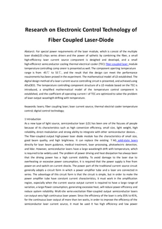
  • 7. DC / DC circuit. DAC1 output control voltage is used as the circuit fault protection control signal. According to Figure 4, the digital control driven by the LD module is realized through programming. Figure 6 shows the physical diagram of the fiber-coupled LED module drive current source and temperature control module. Figure 7 is a sampling waveform diagram of the semiconductor laser power supply current at the moment of system power-up under the environment of -40°C. It can be seen that the semiconductor laser driving circuit has no power-on impact.
  • 8. 4. Temperaturecontrol technology of optical fiber coupled LD module According to different use conditions, the temperature control of the LD module can adopt cooling methods such as water cooling and air cooling. In this paper, the semiconductor refrigeration (TEC) temperature control working mode is adopted, which has the advantages of small size and low power consumption. Figure 8 is a schematic diagram of the LD drive module and TEC control structure. It is mainly composed of LD chipset, chip carrier, PIN back-monitoring photodiode, TEC thermoelectric device, NTC platinum resistance temperature sensor, LD drive laser current source module, TEC temperature control current source module, etc., Pwr. The line filter is an electromagneticcompatibility filter. The schematic diagram of the TE module temperature control circuit of the LED module in Figure 8 is shown in Figure 9. A platinum resistor Rt with a positive temperature coefficient is attached to the surface of the chip carrier. A CC4 mA constant current source provides a DC bias for the platinum resistor temperature measurement. The current source is a small current constant current source composed of an operational amplifier. By detecting the DC voltage across the platinum resistor, the temperature and temperature change rate of the LD module are calculated to determine the use of different TEC drive currents under different environmental conditions to achieve The purpose of optimizing (or nearing optimal) temperaturecontrol.
  • 9. V / I conversion circuit composed of DC / DC conversion, etc., whose output current is proportional to the control voltage, provides driving current for TEC, and its output current is controlled by the DC voltage output from the DAC0 port of the ADUC8311 single-chip microcomputer. The current is between 0 and 5 A. Continuously controllable. The DC voltage output from the DAC1 port is used to control the on / off of the V / I conversion circuit to complete the power protection function. The switches S and S in the converter bridge circuit consist of non-contact switches with MOS field effect transistors with extremely low on-resistance. The two I / O ports of the microcontroller control the on and off of the switches S1 and S2. Simultaneously turn on, make S1 and S2 have the interlock function in the circuit design. The cooling or heating mode is changed by changing the direction of the current flowing through the TEC. In the figure, Rs is the TEC working current detection sampling resistor, and the working current flowing through the TEC is calculatedby detecting the voltage across it. 4.1 Optimization of TEC working current Application environmental conditions require the TEC temperature control system to have the fastest response speed and high efficiency as possible. After completing the selection of the TEC device and the design of the heat dissipation structure of the laser module, the coefficient of performance ξ of TEC can be expressed as: ξ = f (I, Tcs, ΔT), (14) In the formula, the control terminal temperature Tcs is a preset temperature value, so the working current I and the temperature difference ΔT are the main factors affecting the coefficient of performance. The relationship between the heat of the control terminal TEC of the TEC, the coefficient of performance ξ, and the operating current I of the TEC is shown in Figure 10. It can be seen that when the coefficient of performance ξ is the largest, Zc cannot reach the maximum. When Zc reaches the maximum, the coefficient of performance will decrease. Therefore, the best working area of the refrigeratoris: Iopt ≤ I ≤ Imax. (15) In the optimal working area, when I increases, the heat at the control end increases and the work efficiency decreases.
  • 10. 4.2 Temperaturecontrol method of optical fiber coupled LD module The temperature range of the external working environment of the fiber-coupled LD module is wide. In order to control the wavelength of its output laser, avoid excessive wavelength drift, and decrease the emission efficiency when the junction temperature increases, it is required to control the temperature around the LD module at -5°C to 20 ℃. As shown in Figure 10, when the driving current of TEC is between Iopt and Imax, although the heat at the control end increases with the increase of the driving current, the rate of change of heat dzc / dt decreases significantly, even when I> Imax dzc / dt is negative. As shown in Figure 11, the system uses a combination of fuzzy control and traditional PID control. When the temperature exceeds the set temperature range, a fuzzy control algorithm is used, which is determined based on the detected control end heat Qc and its change rate dQc / dt. The magnitude of the control current I and its rate of change is found by the algorithm to approximate Iopt. When the temperature enters the set temperaturerange, it switches to the PID control algorithm.
  • 11. Figure 12 shows the temperature rise curve around the chip carrier measured by the TEC heating control under the ambient temperature of the LCD module at -55°C. Figure 13 shows the cooling curve around the chip carrier measured by the TEC cooling control under the ambient temperature of 55°C. It can be seen that the steady-state temperature change curve of the temperature control system has a large fluctuation (overshoot), which is caused by the laser module emitting a laser, which generates a heat loss of more than 30W, which causes the temperaturearound the chip carrier to rise continuously.
  • 12. 5 Conclusion Based on the fiber-coupled LD module drive current source circuit model, a mathematical model of a high-efficiency current source system based on PWM DC / DC conversion technology is established, and a design method to avoid the current impact caused by power-on of the current source is proposed and analyzed. The main factors affecting the accuracy and stability of the current source are described. By establishing an optimized current source equivalent second-order analog system mathematical model and transforming the Jiang analog system into a digital system, the digital design of the current source control circuit of the LD module was realized, and the LD module based on the ADu8C31 microcontroller was successfully developed to drive the current source component. , Improve the stability and reliability of the c urrent source system. As the laser chip junction temperature rises, its output optical power will decrease and its wavelength drift. A temperature control structure model of the LD module based on TEC is proposed, and a digital model of a temperature controller with strong applicability is established. An optimization design method is proposed for the performance coefficient ξ of the TEC, the heat Qc at the control end, and the working current I of the TEC. By using the ADu8C31 single-chip microcomputer to adaptively adjust the respective working current I of the TEC by detecting the temperature and the temperature change rate, the system temperature control has the characteristics of faster response time and smaller steady-state overshoot. The mechanical dimensions of the fiber-coupled LD module driving current source component and the laser module temperature control component are 64x48mmx22mm, the output electric power is greater than 50W, the current source efficiency is more than 85%, and the output current is continuously adjustable from 0 to 5A. 0.5%, the environmental test proved that the design index requirements were met.