Recommandé

Recommandé
Contenu connexe
Tendances
Tendances (19)
En vedette
En vedette (10)
Similaire à Offshore 1D infinite slope modeling in seismic conditions with opensees
Similaire à Offshore 1D infinite slope modeling in seismic conditions with opensees (20)
Dernier
Dernier (20)
Offshore 1D infinite slope modeling in seismic conditions with opensees
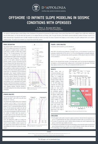
- 1. OFFSHORE 1D INFINITE SLOPE MODELING IN SEISMIC CONDITIONS WITH OPENSEES C. Piatti, L. Zuccarino & O. Zanoli Corresponding Author Contact: claudio.piatti@dappolonia.it The response of submerged slopes to seismic loading is often a key-element in the geohazard risk assessment for offshore projects. Seismic-induced slope failures in NC or slightly OC clays usually involve relatively large areas but limited depths, such that the infinite slope assumption can be employed (Biscontin and Pestana, 2006). This paper describes a Finite Element numerical model which simulates the dynamic response of an infinite submerged slope. A hypothetical uniform normally consolidated soil profile was chosen as case study. The results of transient-in-time analyses are used to develop a site specific stability plot which can be useful for preliminary design. The outputs of the simulations are compared with pseudo-static solutions. DYNAMIC ANALYSES The assumed soil properties are typical of a NC medium plasticity clay (Table 1) with a stiff to very stiff soil at the base (Vs = 260 m/s). The assumed shear modulus decay curve is compared to literature curves in Figure 2. A set of seven time historieswasselectedconsideringarangeof magnitude between 5.0 and 7.5 and epicentral distance less than 40 km. The time histories were scaled to the stiff soil Peak Ground Acceleration (PGA), applied at the base of the model and propagated through the soil column. The condition of incipient failure was assumed to be reached when the mean permanent shear strain exceeded 10% (established on the basis of advanced laboratory tests results). Strain and displacement profiles are strongly time history dependent (Figure 3). This reflects the inherent record to record variability in seismic response, but also suggests that a proper selection of time histories representative for the site is a key issue for strategic projects. CONCLUSION ƒƒ The FE analysis results would correspond to apply an acceleration reduction factor β ranging from 0.10 to 0.15, i.e. significantly lower than values recommended by standard codes (e.g. Eurocode β ≥ 0.5) ƒƒ The choice of a pseudo-static seismic coefficient without accepting some seismic displacements could lead to a conservative slope stability assessment ƒƒ Theeffectivenessandreliabilityof theproposedmethodologyisenhancedbyhighqualityinputgeotechnical data and advanced laboratory test results such as bender elements, resonant column and cyclic tests ƒƒ The methodology can be readily applied to more complex soil stratigraphy REFERENCES Biscontin, G. & Pestana J. M. 2006. Factors affecting seismic response of submarine slopes. Natural Hazards and Earth System Sciences 6(1): 97–107 PEER 2010. Open System for Earthquake Engineering Simulation (OpenSees) http://opensees.berkeley.edu MODEL DESCRIPTION The numerical model is implemented using OpenSees (PEER,2010)softwareandconsistsof a1Dsoilcolumn with application of suitable boundary conditions and gravity loads to simulate an infinite slope condition (Figure 1). The 1D model represents a 100 m high soil column. It is constituted by 500, four nodes, quadrilateralelementstoallowanadequatepropagation of the desired range of frequencies. Lateral infinite extension of the model is obtained by tied-nodes boundary condition. The soil is represented using the Pressure Independ Multi Yield material model. This is a general constitutive model for cohesive soils in which the soil strength is independent of effective stress. The soil is modelled as a nonlinear hysteretic material with a Von Mises multi-surface kinematic plasticity model. The model focuses on reproduction of the soil hysteretic elasto-plastic shear response including permanent deformation. Plasticity is exhibited only in the deviatoric stress-strain response. Plasticity is formulated based on the multi-surface (nested surfaces) concept, with an associative flow rule. The nonlinear shear stress strain backbone curve is represented by the Kondner hyperbolic model. Numerical damping is specified as a combinationof stiffnessandmassproportionaldamping matrix (Rayleigh damping). Hysteretic damping is intrinsically developed from the nonlinear elasto-plastic soil behavior. Figure 2. Assumed shear stiffness degradation curve compared with literature curves for cohesive soils. Figure 3. Permanent shear strain and horizontal displacements at the end of seismic motion for α = 14° and PGA= 0.3 g. Figure 4. Stability chart: FEM results compared with pseudo-static solutions. PSEUDO - STATIC ANALYSES In accordance with Eurocode 8, kh can be calculated as: where PGA* is the peak ground acceleration on soil type A (rock), g is the acceleration of gravity, ß is an acceleration reduction factor (0.5 for rock to 0.7 or 0.9 for soft soil depending on earthquake magnitude). The factor of safety for a submerged slope under the assumption of infinite slope for total stress conditions can be computed as: where Su is the undrained shear strength, α is the slope angle, γ and γ’ are the total and submerged soil unit weights, kh is the horizontal seismic coefficient and z is vertical depth to the shear plane. The critical slope angle as a function of kh (i.e. PGA) can be obtained for the limit case of Fs =1. RESULTS Shear strains tend to concentrate downslope in the upper 5 to 10 m of the profile (Figure 3). A stability plot was developed to define the boundary between stable and unstable conditions (Figure 4). The FEM stability curve represents the critical slope angle as a function of PGA values (i.e. return period). PGA values are referred to the acceleration applied at the base of the model. Since the dynamic stability analysis is performance based, the condition of limit stability (or critical condition) is strictly related to the threshold criterion assumed (permanent shear strain reached 10%). The stability curve obtained for the NC cohesive profile is almost linear in the range of PGAs considered. Figure 1. Sketch of the model. The full paper can be downloaded here