Combustion in Internal Combustion (IC) Engines
•
3 j'aime•2,176 vues

A century and nearly two decades later there has been immense progress in the field of IC engines, though many phenomenon taking place are still to be understood physically. This blog aims at comprehension of some of the astonishing research that has been done in this field restricting our interest to combustion with some amusing facts.

Recommandé
Contenu connexe
Tendances
Tendances (20)
En vedette
En vedette (20)
Similaire à Combustion in Internal Combustion (IC) Engines
Similaire à Combustion in Internal Combustion (IC) Engines (20)
Plus de iMentor Education
Plus de iMentor Education (20)
Dernier
Dernier (20)
Combustion in Internal Combustion (IC) Engines
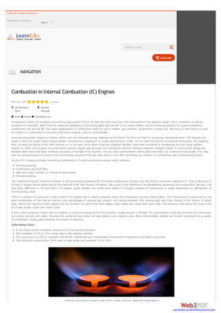
- 1. Login or Create an Account My Account Contact USD $ Search Course Cart (0) NAVIGATION Combustion in Internal Combustion (IC) Engines Rate this item (4 votes) 28 February, 2014 Print Email: Ganesh Visavale Comments (1) Combustion marks its existence since Stone Age period in form of mere fire and since then this phenomenon has played a major role in evolution as well as revolution of mankind. Right from its mediocre application of providing light and warmth to its sheer brilliant use for rocket propulsion for space expedition, combustion has done it all. The major applications of combustion being its use in boilers, gas turbines, automotive, rockets etc, the focus of this blog is to give an insight on combustion in internal combustion engines used for automobiles. Internal combustion engine is a device which uses the chemical energy released by the fuel in the form of heat for producing mechanical work. The engines are made to work for cycles which include intake, compression, expansion or power and exhaust cycles. Let us trace the history of internal combustion (IC) engines first, turning the clocks in the 19th century i.e. in the year 1876 when a German engineer Nicolaus Otto was successful in developing the first spark ignition engine. In 1892, the concept of compression ignition engine was brought into practice by another German engineer, Rudolph Diesel. A century and nearly two decades later there has been immense progress in the field of IC engines, though many phenomenon taking place are still to be understood physically. This blog aims at comprehension of some of the astonishing research that has been done in this field restricting our interest to combustion with some amusing facts. Study of IC engines includes interesting combination of varied physical processes which includesThermodynamics Combustion and fluid flow Heat and mass transfer or transport phenomena Chemical kinetics The method of fuel air mixture formation is the governing parameter for the whole combustion process and the further processes related to it. The combustion in SI and CI engine hence varies due to the method of air fuel mixture formation. Also due to this difference, the parameters governing the combustion will vary. The first basic difference is the fact that in SI engine, spark initiates the combustion while in CI engine initiation of combustion is solely dependent on self ignition of the fuel being used. There is variation of pressure in every cycle of IC engine and it majorly depends upon the combustion process taking place. This combustion is governed by the local composition of the fuel air mixture, the percentage of residual gas present and mixing between this residual gas and fresh charge in the vicinity of spark plug. Hence the maximum heat release and the duration for which this heat release takes place also varies with each cycle. The pressure and hence the torque and the brake power varies with every cycle. A fuel, when combusts reacts with an oxidizer to produce energy and in this process, stable species is formed. For hydrocarbon fuels the products of combustion are carbon dioxide and water. However the entire process does not take place in one reaction step. Many intermediate radicals are formed resulting from a series of competition taking place between N number of reactions. Interesting facts : In any hydrocarbon oxidation process CO is the primary product. The oxidation of CO to CO2 comes late in the reaction scheme. The conversion to CO2 is retarded until all the original fuel and intermediate hydrocarbon fragments have been consumed. The hydroxyl concentration (OH) rises to high levels and converts CO to CO2. Internal combustion engine seen from inside (Source: National Geographic) converted by Web2PDFConvert.com
- 2. Combustion in spark ignition engine Unlike CI engines where the fuel in injected after air has been heated at the end of compression stroke, in SI engines air fuel mixture obtained in the carburettor is supplied through intake manifold in the combustion chamber. At the end of compression stroke, the thoroughly mixed fuel is ignited with spark generated by a spark plug. The flame that is created on ignition by spark plug is generally circular. After spark is discharged, there is a period during which energy release from the flame being developed is too small for the pressure rise. On further propagation of flame, the pressure rises and reaches a maximum after top dead centre and then decreases as during power stroke the cylinder volume increases. These processes vary cycle to cycle due to change in the pressure, volume fraction of fuel ignited. The flame growth depends on the local air fuel mixture as well as its motion in the engine cylinder. The mixture composition in the vicinity of the spark plug at the spark discharge governs the development of flame front in early stages. The density of unburned mixture ahead of the flame front is as large as four times the density of burned gas which lies behind the flame. 25% of the mass still remains unburnt even if the entire combustion chamber is enflamed. Hence combustion in SI engines can be divided in the following phasesSpark ignition Early flame development Flame propagation Flame termination A term called maximum brake torque (MBT) denotes the optimum time of spark which if obtained produces maximum expansion work. If the spark timing advances or retards than that of MBT less torque is produced. The flame established by spark plug is essentially laminar of the thickness 0.1 mm. This flame which appears like a thin reaction sheet is moderately wrinkled because of the local variation of air flow field. The flame becomes highly wrinkled as it progresses further in the expansion stroke, reaching the far end of wall. This is the time when maximum pressure occurs. The turbulent flame is also called as “Brush” whose thickness becomes of the order of 1 cm. Flame propagation in a stoichiometric ethylene-air mixture, 6 ms after ignition (Source: Transient Plasma Systems) Amazing facts about ignition: During ignition the gas around the spark plug ionizes and becomes plasma, called as breakdown phase The temperature at this point is around 60000 K which is accompanied by a pressure wave which causes heat transfer and reduces its temperature to 10000 K and all this takes place in 1 nano second Following breakdown phase is arc phase with 6000 K temperature and duration having time scale in microseconds. The last phase is the glow phase is the glow discharge phase having temperature 3000 K Three different phases of combustion in a cylinder (1. Ignition and flame propagation in quiescent atmosphere, 2. Wrinkle formation due to subtle turbulence, 3. Large turbulence affecting the flame) (Source: http://www.cssci.org/ , Central States Section of The Combustion Institute) Video-1: The below video shows Schilieren photography of a square wall piston engine showing all the strokes i.e from intake, compression, combustion and power stroke converted by Web2PDFConvert.com
- 3. and then exhaust stroke. The valve opening and closing can be clearly seen. (Source: www.youtube.com) Combustion in CI engineIn CI engine after induction of air into the combustion chamber, the compression stroke begins and then at the end of this stroke fuel is injected at very high velocities in one or more jets. The fuel gets atomized due to high velocity injection and vaporises due to high temperature. The fuel reaches the self ignition temperature and thus combustion begins. In CI engines the following combustion phases taking place in expansion stroke is divided in following phases: Ignition delay - This is the period between fuel injection initiation and beginning of combustion Premixed or rapid combustion phase - The fuel accumulated in the combustion chamber ignites as the fuel reaches its self ignition temperature. High heat release rate is obtained during this phase. Mixing controlled combustion phase - The burning rate in this phase is of controlled manner and the heat release decreases in this phase. Late combustion phase - Heat release rate is lowest in this phase, as small amount of fuel is available for burning. In CI engine the fuel when sprayed into the combustion chamber, the fuel droplets are larger than the diameter of nozzle at lower jet speed, called as Rayleigh regime. The break up in this regime is due to unstable growth of surface waves caused by surface tension. As the jet velocity increases, forces due to relative motion of jet and surrounding also increase which are higher than surface tension force and thus resulting in breakup of fuel into drop size equal to jet diameter. This is called first wind induced break up regime. Further increase in jet velocity decreases the drop diameter thus atomizing it. Atomization process (Source: J. Warnatz, U. Mass, R. W Dibble, Combustion) Atomized drops get evaporated when they come in contact with hot ambient air inside the combustion chamber. The rate of evaporation depends upon: Heat transfer taking place from the surrounding to the drop Drop deceleration due to drag Mass transfer of the fuel that has been vaporized in the direction away from drop Heat transfer coefficient between air and drop Mass and temperature of the droplet The evaporated fuel simultaneously mixes with air and auto ignites itself at the end of compression stroke thus producing power. Few facts about injection : The cylinder pressure at injection is 50 to 100 atm Fuel injection pressure is in the range of 200 to 1700 atm For multi cylinder engines producing 20 to 100 kW Brake power (BP) fuel injectors work at a pressure between 300 to 1200 atm Video 2: The following video shows injection in a square piston engine with glass wall, which is being played in slow motion. converted by Web2PDFConvert.com
- 4. (Source: www.youtube.com) Video 3: The flame propagation can be clearly seen in the below video. (Source: www.youtube.com) Factors governing combustion in engines : Mixing of fuel and air Compression ratio Spark timing (For SI)/ self ignition temperature (For CI) Turbulent mixing Load on engine Engine speed Fuel characteristic like octane number (For SI)/ cetane number (CI) Dual fuel combustion of syngas with different amounts of injected diesel fuel (Source: Combustion and Exhaust Emission Characteristics of Diesel Micro-Pilot Ignited Dual-Fuel Engine, Ulugbek Azimov, Eiji Tomita and Nobuyuki Kawahara) Abnormal combustion in SI and CI engines : Abnormal combustion generally results in high pressure and temperature rise in combustion chamber which may result in severe engine damage. It even produces noise which is undesirable. Knock is defined as spontaneous ignition of the fuel at the end part of the gas which is just ahead of flame propagating through combustion chamber. Spark knock occurs when the end gas ahead of combustion flame front ignites and substantial pressure rise takes place due to instant heat release. Another reason of abnormal combustion is surface ignition wherein pre ignition or post ignition of the charge prior to actual combustion due to hot surfaces like spark plug tip or valves. Methods to avoid abnormal combustion in SI engines : Using fuel having high octane number Retarding the MBT timing of spark Reducing intake temperature and pressure In CI engine, the knock occurs when fuel has high ignition delay and the fuel accumulates to a larger quantity such that a large amount of fuel ignites causing abrupt increase in pressure and heat release. The factors that are responsible for spray formation and evaporation will also affect ignition delay and knock in CI engine. Intake air pressure and temperature are major factors affecting knock. Methods to avoid abnormal combustion in CI engine : Using fuel having high cetane number Reducing intake temperature and pressure Coming up in next part : converted by Web2PDFConvert.com
- 5. In this part, we saw major phenomenon taking place during combustion in IC Engines. In the next blog, we will see application of CFD in analysis of combustion in IC engines, how it is done and what are the merits as well as limitations of CFD. References: 1. 2. 3. 4. 5. 6. 7. 8. John B. Heywood, Internal Combustion Engine Fundamentals, Tata McGraw-hill Irvin Glassman, Richard A. Yetter, Combustion, J. Warnatz, U. Mass, R. W Dibble, Combustion Ulugbek Azimov, Eiji Tomita and Nobuyuki Kawahara, Combustion and exhaust emission characterstics of Diesel Micro-Pilot Ignited Dual-Fuel Engine, http://www.cssci.org/ , Central state section, The combustion institute www.nationalgeographic.com , Natinal geographic www.transientplasmasystems.com, Transient plasma systems www.youtube.com; http://www.youtube.com/user/kcedrone?feature=watch Share 10 Like 10 Tweet Share 3 12 Share 1 Read 305 times Fundamentals Tagged under Fundamentals Combustion Ganesh Visavale Co-Founder & General Manager, LearnCAx Inspire | Educate | Mentor Website: LearnCAx.com Email: ganesh@cctech.co.in Latest from Ganesh Visavale An Insight into Cavitation Phenomena What's new in CAE ? Related items An Insight into Cavitation Phenomena in Fundamentals By Ganesh Visavale We all must have heard about the term ‘Cavitation’ sometime, more certainly if we have dealt with pumps or similar fluid application and probably might have also seen some effects of ‘Cavitation’. Cavitation is very common term in engineering domain especially if we are dealing with fluids. So let us have a detailed insight into this ‘Cavitation’ phenomenon through this blog. The Falling Droplet in CFD By Ganesh Visavale We all have seen the rain drops falling on roof tops or road or car roofs, or water droplets falling from tap. When we usually see these phenomenons occur around us they happen within no time. We don’t even notice them. But if we look closely there are very complex physics involved in them. What if we could really slow down time and observe closely these phenomenon occurring? Like this video from Discovery Channel which shows a slow motion capture of a droplet falling into a liquid surface. Multiphase Flow Modeling : Part 4 - Mathematical treatment in Fundamentals By Ganesh Visavale After a thematic representation about the different modeling approached of multiphase flows in Multiphase Flow Modeling using CFD, we shall now have a look at the mathematical treatments involved behind all these models viz., Eulerian-Lagrangian, Eulerian-Eulerian and Volume of fluid. Multiphase Flow Modeling : Part 3 - CFD Approaches in Fundamentals By Ganesh Visavale "Thermodynamically a phase refers to states of matter which we generally classified as solid, liquid and gaseous". (Clayton T. Crowe; Multiphase Flow Handbook). Before we enter into any further discussion it is very important to understand what exactly do we mean by phase. From modeling point of view there is a slight modification from the definition. Multiphase Flow Modeling : Part 2 - Terminologies in Fundamentals By Ganesh Visavale The terminologies used in the study of multiphase flows are as follows : Continuous phase or Primary phase : This is basically the carrier fluid, that is present in bulk. Dispersed phase or Secondary phase : This is the discrete phase which is usually in the form of particles, droplets, or bubbles. More in this category: « An Insight into Cavitation Phenomena converted by Web2PDFConvert.com
- 6. #1 Ganesh Visavale 2014-03-04 17:18 0 Quote Hi All, this is the first blog in the series to follow on CFD study of Combustion. I would be glad to reply if you have any specific query on this article. Feel free to contact at ganesh cctech.co.in Refresh comments list Add Comment Name (required) E-mail (required, but will not display) Notify me of follow-up comments Refresh Send about us support follow us Copyright © 2014 LearnCAx, CCTech. All Rights Reserved. www.LearnCAx.com, www.cctech.co.in converted by Web2PDFConvert.com