DESIGN AND ANALYSIS OF HEAVY VEHICLE CHASSIS USING HONEY COMB STRUCTURE
20160406_Project report_Final
1. STAFFORDSHIRE UNIVERSITY
FACULTY OF COMPUTING, ENGINEERING AND TECHNOLOGY
NEGOTIATED FINAL PROJECT
BEng (Mechanical)
Project Report
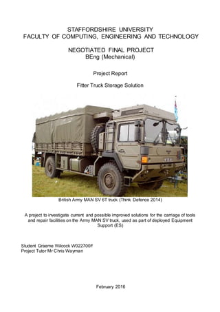
Fitter Truck Storage Solution
British Army MAN SV 6T truck (Think Defence 2014)
A project to investigate current and possible improved solutions for the carriage of tools
and repair facilities on the Army MAN SV truck, used as part of deployed Equipment
Support (ES)
Student Graeme Wilcock W022700F
Project Tutor Mr Chris Wayman
February 2016
2. i
Abstract
“Create and design an adaptable and modular storage system for the carriage of tools and
repair assets on the Army MAN Support Vehicle, used as part of deployed Equipment
Support (ES)”.
When deployed out of barracks ES personnel need to store tools, special test equipment
and spares on the MAN Support Vehicle (SV). There is currently no standard storage unit
for this and local modifications for storage are proving time-consuming to implement,
potentially unsafe and unable to accommodate all items securely.
In order to understand the situation this project first established a customer requirement of
equipment to be carried. This was achieved through a customer survey of 150 personnel
from across the Land ES environment. From this a Product Design Specification (PDS)
was created with a list of items and criteria deemed essential. Research into current
storage solutions, civilian modular systems and complete ISO container based systems
was conducted with the findings assisting in the creation of a self-designed storage
system.
This design was based around the dimensions of standard NATO storage boxes and
vehicle mechanic toolboxes. By utilising Computer Aided Drawing (CAD) software a
technical design specification was created for a storage unit based around 4 main pillars
of box section steel combined with 3 shelving units that can be moved up and down the
pillars to accommodate different storage requirements. The pillars also allowed for further
shelves to be used to extend the storage unit lengthways thereby creating a modular
system. A securing bracket was designed to mount onto the truck bed to which the
storage unit could sit on and mathematical calculations proved the integrity of the design.
A concept prototype was built to prove the practicality of building the design within local
unit capabilities, although achievable it ultimately highlighted the high degree of accuracy
and time required and was therefore deemed unfeasible to manufacture within local unit
capabilities, and full production should be sought through civilian industry. Further CAD
modelling was instead used to prove the storage capability of the design.
This report concludes that to provide deployable storage for ES equipment across a range
of customer bases, while maintaining the crucial ability to quickly remove it, an adaptable
and modular system such as the one this project has designed offers the best solution.
Despite the manufacturing requirements this solution is both practical and achievable
whilst at a greatly reduced cost when compared with containerised solutions.
3. ii
Acknowledgements
This project would not have been possible without the support and help of the
following persons:
1. Mr Daniel Errington from DE&S. Senior manager for the MAN vehicle
for initial project assistance.
2. Mr Gary Daniels. Manager for all Deployable Machine Repair
Solutions for information on ISO container based systems.
3. Mr Chris Wayman. Project tutor from Staffordshire University for
continual assistance and guidance.
4. Captain Chris Marsh (REME). My line manager and senior officer
within my workshop for his authorisation of the use of Army facilities.
5. Members of 6 RLC LAD. The authors peer group who were
instrumental in synthesising ideas.
6. Members of the ES Land environment. For their time and effort in
completing the customer surveys without which no specification
could’ve been created.
4. iii
Contents
Chapter Page
Abbreviations ...................................................................................................................... iv
1. Introduction................................................................................................................. 1-1
2. Project Management ................................................................................................. 2-1
3. Identifying the Required Change............................................................................. 3-1
4. Designing the Change .............................................................................................. 4-1
5. Produce the items to effect the change.................................................................. 5-1
6. Implement the Change.............................................................................................. 6-1
7. Monitor the Effect....................................................................................................... 7-1
8. Conclusion and Recommendations........................................................................ 7-4
Bibliography...................................................................................................................... 7-6
Annexes
A Project Analysis Table ...............................................................................................A-1
B Initial Gantt Chart ......................................................................................................A-2
C Updated Chart ............................................................................................................A-3
D Fitter truck storage data requirements ....................................................................A-4
E Technical Design Solution ........................................................................................A-5
F Storage Unit Calculations ..........................................................................................A-6
G Securing Frame Calculations ...................................................................................A-7
Appendix 1 to Annex G&H Data Tables ......................................................................A-8
5. iv
Abbreviations
AESP Army Equipment Support Publication
ASM Artificer Sergeant Major
CCM Configuration Change Management
CAD Computer Aided Design
CD CSS Capability Director Combat Service Support
CES Cambridge Engineering Selector
COTS Comercial Of The Shelf
DE&S Defence Equipment and Support
DMS Deployed Machine Shop
DMRS Deployable Mechanical Repair Systems
DTSS Deployable Technical Support Solutions
ES Equipment Support – i.e. maintenance, inspection and repair
JSP Joint Service Publication
LAD Light Aid Detachment
MOD Ministry Of Defence
NATO North Atlantic Treaty Organisation
PME Pump Mounted Equipment
POL Petroleum, Oil and Lubricants
PT Project Team
REME Royal Electrical and Mechanical Engineers
RM Royal Marines
TC OPO Transportable Container Operational
TDU Trials and Development Unit
SV Support Vehicle
VM Vehicle Mechanic
6. 1-1
Chapter 1. Introduction
1.1 Background
1.2 Project Selection
1.3 Selection of a project
1.4 Fitter Truck
1.5 Project Aim
1.6 Objectives
1.7 Success Calculation
1.1 Background
As a vehicle artificer in the Army’s Royal Electrical and Mechanical Engineers (REME) the
author chose a project based on land equipment as this is relevant to his career and
interest. Three potential projects were initially investigated and these were found through
the authors experience, discussion with colleagues and advice from the MOD Defence
Equipment and Support (DE&S) Project Teams who manage all equipment for the MOD.
1.2 Project Selection
Three options were considered:
1. Quad bike loading. Investigate a means for safely loading and unloading
quad bikes (fig 1) from flatbed trucks without the use of a crane in order to reduce
the logistics burden for quad bikes.
2. Recoveryvehicle winch snapping. Investigate the reasons for failure of
the winch fairlead shackle on the MAN SV recovery vehicle (fig 2).
3. Repair section “fitter” truck. Investigate current and possible improved
solutions for the carriage of tools, POL, repair facilities and specialist items on the
MAN SV truck in support of deployed operations.
Fig 1. Quad bike Fig 2. MAN SV Recovery
(British Army n.d Crown Copyright) (Defence update n.d)
7. 1-2
1.3 Selection of a project
The technique of “SWOT” analysis was used to help choose between the options. This
highlighted the Strengths, Weaknesses, Opportunities and Threats to each one as shown
in the author’s proposal document. The threats identified during this analysis resulted in
options 1 and 2 being discounted.
In consultation with Staffordshire University project tutor for advice on suitability it was
decided to go forward with option 3, hereafter known as the fitter truck storage project
detailed below. This is relevant to the authors career and interest, has the required
supporting information freely available and access to the equipment.
1.4 Fitter Truck Storage
Army equipment is maintained and repaired by REME sections from Light Aid
Detachments (LADs) attached to each Army unit. When deployed out of barracks they
carry all tools and repair equipment on their vehicles, and in armoured units there are
special armoured repair vehicles available with built-in storage and repair facilities.
However in non-armoured units they use standard issue flatbed trucks such as the MAN
Support Vehicle (SV) 6t (Fig 3.) and convert the back of them in an ad hoc manner to use
as repair trucks with tool storage, spares, vices and drills etc.
Fig 3. MAN SV 6t (CST) (Think defence 2014)
This conversion is done by placing workbenches and storage units on the load bed
secured by ratchet straps, correct securing angles and tensions are difficult to achieve
which results in the equipment moving around during cross-country driving (fig 4) which
8. 1-3
can lead to damage. The storage units are also heavy and cannot be moved by hand
which leads to excessive time to set up the repair truck.
Fig 6. Evidence of items moving around during transport. (Wilcock 2015)
Project Analysis
Project analysis was conducted to look to at the issues, implications and deductions for
this project and this can be seen at Annex A. The project aimed to firstly establish what
the exact requirement for repair trucks was from the Land environment1
. It then
investigated current and alternative solutions before designing and evaluating a self-
designed system. The intent was to design a solution that is easily removable and
modular in nature.
1.5 Project Aim
“Create and design an adaptable and modular storage system for the carriage of tools and
repair assets on the MAN SV truck, used as part of deployed Equipment Support (ES)”.
1.6 Objectives
To complete this project the following objectives have been set:
1. Create a Product Design Specification (PDS) based on feedback
from customer surveys.
1 Defence terminologymeaning users operating on the ground,in this case referring to Army and Royal
Marine units ES units.
9. 1-4
2. Investigate current and alternative options for storage solutions.
3. Propose and design a modular solution for testing by creating a Technical
Design Specification which accommodates the PDS.
5. Investigate feasibility of solution by building an example.
5. Prove chosen solution is fit for purpose.
6. Produce cost evaluation for solution.
7. Validate solution against specification.
8. Complete all objectives in accordance with project timeline.
These were designed using “SMART” principles. They are specific to the REME and the
Army’s fleet of MAN vehicles, they are measurable in that they can be marked as
achieved/not achieved during and at the end of the project, achievable and realistic as
data collection, designing a solution and testing it are within the authors capabilities at the
unit, and time based in accordance with a project timetable.
1.7 Success Calculation
The project will be a success if all objectives have been met and a modular and adaptable
solution has been designed which can be proved to offer a suitable means of storing all
items required by the customer. A validation of the solution will be conducted to show that
each criteria of the PDS has been met whilst remaining within safe design limitations
10. 2-1
Chapter 2. ProjectManagement
2.1 Guidance
2.2 Planning
2.3 Resources
2.5 Technical Review
2.5 Data Requirements
2.1 Guidance
The success of any project depends heavily on the efficient management of it, there are
many established practices for managing projects with PRINCE 2 being one of the most
common. As this project is related to MOD equipment JSP 886 was used as the guiding
doctrine.
Joint Service Publication (JSP) 886, Vol 5, Part 2A. This is the MOD guidance on
Configuration Change Management (CCM) or modification and is open source
information. It details 5 stages for modifying in-service equipment and the project used
these stages as follows:
1. Identify the required change. Issue surveys to units and analyse results
to establish a customer requirement, begin data gathering.
2. Design the Changes. Research safety and other limitations for any
solutions. Research current and alternative storage methods.
3. Produce the items and documentation to effect the change. Produce
detailed design drawings for a modular storage solution, select materials,
and prove design is capable mathematically
4. Implement the Change. Build solution and analyse feasibility. Conduct
cost and ecological analysis.
5. Monitor the Change. Validate solution.
2.2 Planning
When considering the timeline a top down analysis was used by “identifying the major
blocks of work in the project” (Nokes, Major, Greenwood, Allen, & Goodman, 2003) and
then detailing tasks within each of them. The major blocks for this project were the five
stages as defined by JSP 886. These major blocks and tasks were planned on an excel
spreadsheet with time limits for each of them shown at Annex B. A period of up to 12
months was given for this project to allow it to fit in with other commitments. The project
11. 2-2
was broken down into week long blocks which were placed within month periods, the
Gannt chart was used to monitor what was achieved at the end of each month period
(indicated in yellow) against what was planned. Further resources could be added during
the course of the project. 2 periods of 2 week breaks for summer and Christmas were
factored in.
2.3 Technical Reviews
Technical reviews were conducted at the end of each month, following September’s
review it was realised that the research had extended past the aim of the project, with the
author looking at fitter trucks as a whole piece, i.e. the H+S of personnel working on the
back, how electricity could be brought into the back of the truck etc., This was outside of
the aim of the project and so focus was reapplied to only addressing those aspects
directly related to the project aim.
During January’s review it was felt that the manufacture of a full working prototype was
beyond the time available of the author and that more time should be devoted to
mathematical calculations to prove the design with a simpler version of the design
produced to validate the concept. The Gannt chart was therefore altered to reflect this
new approach and is shown at Annex C.
A short notice deployment in support of a European Union Battle Group exercise in April
through to June resulted in the original deadline for completion being pushed back.
However if this had not occurred then the project would’ve been finalised to schedule.
2.4 Resources
The following resources were utilised for this project.
1. Computer Aided Design software. CAD software assisted in drawing a
solution which was then be used to manufacture it.
2. Cambridge Engineering Selector software. While only a reference tool,
this allowed for the investigation of materials properties
3. Microsoft based software. Excel was used for project management and
data analysis, Word was used for project write up and Power Point was
used for presentation work.
12. 2-3
4. Basic hand and machine tools during the build phase with the assistance of
the unit metalsmith.
2.5 Research
A mixed method approach to research was used using questionnaires as the primary
information source to collect quantitative data, in order to establish a customer
requirement, secondary research was used to establish limiting criteria such as size,
weight and legal impediments and then to research current and alternative storage
systems in both the military and civilian domains.
By looking at the key information required it was possible to break this down into more
specific questions to pose or investigate. These are shown at Annex D.
13. 3-1
Chapter 3. Identifying the Required Change
3.2 Primary Research
3.3 Further considerations on survey results
3.4 Customer Requirement
3.5 Specification
3.2 Primary Research
The focus for the first part of the project was to establish exactly why there was a need for
a fitter truck and what was required of it. In order to do this a customer survey was
created to establish a customer requirement from the land environment. Some knowledge
of writing surveys was gained from “a quick guide to research” by Jones T, L. Jones
(2013) states to “place easy important questions near the start, group common themes
and arrange it in a logical manner”, the survey was therefore designed as a set of 10
questions to establish how the customer currently fulfils this capability, what they carry on
it and what they want from a fitter truck.
In order to prove this question set was sufficient an alpha test was conducted by print outs
of the on-line survey and distributed to members within the authors workshop. From this it
was discovered that question 4 did not provide the opportunity to state how many of each
item was carried, this is crucial information as it is needed to calculate size and weight
requirements.
The survey was emailed to 150 personnel across the Land environment within the Army
and the Royal Marines2
. 45 personnel completed the survey and these results were taken
to be indicative of the customer requirement. 4 key questions from the survey were
identified which give the quantative data required and are detailed below. The other
questions in the survey were able to give important information on what the customer
needed to do in a fitter truck and what they would like from it, while not specific to the
issue of storage; they did give a better understanding of the larger issue.
3.2 Results
The results from question one showed that the overwhelming majority of units were using
the MAN SV 6T truck as a vehicle for fitter trucks. This gave a vehicle type to base ideas
on. It was clear however that the other 2 main types of MAN truck (9t and 15t) were also
2Although much smaller in number and less vehicle dependant,the Royal marines still deploya number of
vehicles and therefore also have a requirementfor a deployable fitter truck.
14. 3-2
used by some units; therefore a solution should be adaptable for use across the range of
MAN vehicles in use.
Question 2 explained how fitter trucks are currently fitted out with storage units, the
majority of units use large storage drawers and cages which are then filled with NATO
green storage boxes. Question 3 detailed how these storage units are fixed to the fitter
truck bed, in the overwhelming case they are ratchet strapped to the load bed. The fact
that no units weld their storage units to the truck bed relates to the requirement of it being
easily removable.
Question 4 was the most important question as the answers to this question gave the
amount of equipment that any solution must be capable of handling. It was slightly
disappointing that the number of VM toolboxes carried did not produce a clearer result but
3 was taken as the number of required toolboxes due to this being the highest scoring
result, this is also the total number of personnel that can sit in the driving cab. For each
item the highest scoring number of items was taken as an essential requirement for the
specification, this was caveated by taking bench drill and grinder as an anomaly due to
the low number of responses for them and placing it as a desirable requirement only.
3.3 Further considerations on surveyresults
Further to the results displayed above qualitative data was also received from people’s
opinions and comments, from these the following conclusions were:
15. 3-3
1. That available space for carrying a tent should be available with the
consensus being that an Army issue 9x9 tent would be key.
2. That space should also be available for carrying a Light Field Generator
(LFG).
3. That space should be available for at least 2 X 25 litre drums of Oil.
4. 3 of the questions asked were about how units stored difficult to measure
equipment such as spare parts, large and bulky tools, as well as COSHH and
POL, the common answer was by placing them in green NATO storage containers.
5. That any solution must have the ability to have a worktop placed on top of it
to provide a firm, flat working environment.
6. In-line with the policy detailed in JSP 886 and on advice from CD CSS the
solution must not permanently alter the vehicle but be able to be quickly removed
in order to return the vehicle to its standard cargo carrying variant.
3.4 Customer Requirement
By analysing the information from the survey a customer requirement was designed of
what the customer requires from a fitter truck.
“Based on the feedback from the survey, design a storage solution to store and use the
items identified that is able to be placed onto the MAN SV vehicle whilst complying with all
mandatory safety regulations.”
3.5 Product Design Specification
The Product Design Specification (PDS) is a spreadsheet of the essential, highly desirable
and desirable criteria as defined by the customer surveys (Table 1). The essential criteria
are those items that any solution must be able to achieve. The highly desirable and
desirable criteria are the nice to haves and were used to compare solutions with each
other during comparison if required.
16. 3-4
Table 1. Product Design Specification (PDS)3
31st
Line repair facilities refers to unitworkshops. 2nd
Line repair facilities refers to larger supporting
workshops. Work lasting more than 30 hours would be referred to civilian or Base Overhaul repair.
17. 3-5
Further investigation was conducted to ascertain the importance of each of these items in
relation to the others, i.e. Is a basic toolbox more or less important than a laptop? This
was achieved through the use of pair analysis. By using a group discussion of personnel
from the authors unit it was possible to compare and rank each criteria against the others.
For the purpose of clarity storage items were compared separate to vehicle requirements.
Tables 2 and 3 refer.
Table 2 Pair analysis equipment
Table 3 Pair analysis Vehicle requirements
The pair analysis proves that the toolboxes and not affecting safety are the most important
criteria and one that any solution must be able to accommodate. This will be important to
factor in when comparing solutions.
E1 E2 E3 E4 E5 E6 E7 E8 E9 E10 E11 E12 E13
Total
Score
E1 VMToolbox x 1 1 1 1 1 1 1 1 1 1 1 1 12
E2 VMSupplementary box 0 x 1 1 1 1 1 1 1 1 1 1 1 11
E3 Cable repair kit 0 0 x 0 0 0 0 1 1 0 1 0 1 4
E4 Jacks 0 0 1 x 1 0 0 1 1 0 1 1 0 6
E5 Axle stands 0 0 1 0 x 1 0 1 1 0 1 0 0 5
E6 Portable drill 0 0 1 1 0 x 1 1 1 0 1 0 0 6
E7 Air kit 0 0 1 1 1 0 x 1 1 0 1 1 0 7
E8 Planning board 0 0 0 0 0 0 0 x 0 0 0 0 0 0
E9 Laptop 0 0 0 0 0 0 0 1 x 0 1 0 0 2
E10 JUD 0 0 1 1 1 1 1 1 1 x 1 1 1 10
E11 Tent 0 0 0 0 0 0 0 1 0 0 x 0 0 1
E12 LFG 0 0 1 0 1 1 0 1 1 0 1 x 0 6
E13 Oil drums (25 LTR) 0 0 0 1 1 1 1 1 1 0 1 1 x 8
18. 4-1
Chapter 4 DESIGINING THE CHANGE
4.1 Secondary Research
4.3 Safety Requirements
4.3 Alternative Solutions
4.4 Analysis of alternative solutions
4.5 Selecting a solution.
4.1 Secondary Research
With a clear and detailed customer requirement it was then necessary to define the
limiting criteria against which the solution must adhere to as well as investigating current
storage systems in order to draw out best practices. The secondary research was
therefore to investigate the following:
1. Safety Requirements. This is based around ensuring that the storage
units are secured correctly to the vehicle.
2. Alternative Solutions. Investigating the current storage solutions as well
as alternative ideas from within the military and civilian areas to generate ideas for
a modular storage system.
4.3 Safety Requirements
Loading
Load Interfaces Safe Designers Guide. This document produced by MAN
Nutzfahrzuege AG is the manufacturers guide for loading equipment onto the MAN SV. It
consists of a series of technical drawings describing loading envelopes to assist users in
placing loads onto the truck to ensure the Centre of Gravity (C of G) is not dangerously
altered. MAN 2014 states that “If the load falls within the load envelopes, no further
testing is required”, meaning that provided the load can be placed within the load
envelopes then it will be deemed safe to carry.
Page 22 of MAN 2003 provides a pictorial representation of the load envelope (not open
source information), this detailed the exact weight limits across the bed, and it also gave a
height limit of 1.3m. This gave boundary limits for any solution; the storage solutions must
be less than 1.3 m tall and not exceed the weights as indicated, the lowest weight of
1000kg as indicated was used for this project. The total weight on the load bed must also
remain under 6000Kg and the imbalance between left and right hand side weights must
be under 6%.
19. 4-2
Securing the load to the bed
Code of Practice for Carriage of Loads. The Department for Transport (DfT) code of
practice for load carriage states that:
“The strength of the load restraint must be sufficient to withstand a force not less
than the total weight of the load forward…and half of the weight of the load
backwards and sideways”. (Department for Transport. 2002)
This means that the effect of braking causing the load to move forwards is the primary
area for restraint. The MAN SV trucks have a series of lashing points on the flatbed for
load security as shown in fig 1 and these are what are currently used to lash the items to
the flatbed with a large strap, of note is the statements made in the code of practice about
the use of lashings and the angle of them, DfT (2002) states that lashings must “not be at
an angle greater than 60o
as the lashing force is greatly increased above this”. This would
be difficult to achieve and still include the number of storage units required and could also
be a reason why the current solutions are moving about during cross-country driving.
Fig 1. MAN SV flatbed (Think Defence 2014)
DfT 2002 also states that the restraining effect from “friction between the load and the
vehicle platform…should be regarded as a bonus”, this means that any storage solution
must be securable without relying on friction as a means of restraint.
DfT 2002 is backed up by the European best practice guidelines on cargo securing for
road transport (EUROPEAN COMMISSION DIRECTORATE-GENERAL FOR ENERGY
AND TRANSPORT). This gives a guide of inertia forces acting on loads as:
20. 4-3
a. 0.5 x weight of the load when accelerating.
b. 0.5 x the weight of the load when cornering.
c. 0.8 of the load when decelerating.
The force required to be restrained will be proportional to the total mass of it. Restraining
force can be supplied by strapping the load to the bed through the lashing points to
provide a force equal to the inertia force or bolting the storage units to the load bed with
bolts of shear strength greater than the inertia force acting on them.
4.4 Alternative solutions
Current in-service storage solutions
The army is currently equipped with several means of storing kit and equipment and these
are often used by units when designing local fitter trucks. The pictures below show the 2
most common items, Chest unit twin drawer (fig 3) and Container Bulk (fig 4). However
these are general purpose storage units and not specifically designed for mounting on the
MAN SV truck.
Fig 3. Chest Unit Twin Drawer Fig 4. Container Bulk
Although these are secure and well-built storage items they suffer in that the means used
to secure them to the flatbed is with the use of ratchet straps, due to the size of them and
the desirable position for placing them on the bed (i.e. along the sides so as to allow an
area to walk in the middle) they are difficult to secure sufficiently in accordance with the
DfT code of practice, the result being a load that moves around during driving.
Advantages Disadvantages
Provides a ready to use system. Heavy mass of each unit means they can
only be moved using MHE.
21. 4-4
Sturdy, durable construction Difficult to secure sufficiently with ratchet
straps.
Another common item used by the MOD for the storage of smaller items is the NATO box,
based on the Euro box (fig 5) this is a plastic box which comes in a variety of sizes.
These boxes are durable, waterproof, oil resistant and not easily damaged.
Fig 5 Euro Box (Think Defence 2014)
The elegance of this system of storage units is the ability to stack them neatly and this
comes about from an ISO arrangement of sizes whereby the boxes share a common
width and length but with 3 different heights. A smaller box is dimensioned so as to be
half the length of the larger boxes and so 2 small boxes can sit on top of the larger box.
These boxes are universally used throughout the MOD for storage and in particular are
used throughout ES units to store tools and spare parts (fig 6), an ideal solution would
therefore encompass a method for using these boxes, as this would allow for a rapid
transfer of stores and spares from workshop buildings to fitter trucks and back again.
22. 4-5
Fig 6 NATO Storage boxes in general use
In addition these boxes have also been seen fitted to Dakar Rally support trucks (fig 7),
these are similar to the fitter truck concept in that mechanics are working and living of
these trucks and need to carry forward all tools and spares.
Fig 7 Dakar rally support truck (storage boxes in centre)
Advantages Disadvantages
Already in use throughout the Army. Requires a sufficient storage unit to hold
them securely which means a new design
Modular design allows for different options
Strong, durable and water/oil resistant
23. 4-6
Deployable Mechanical Repair Systems (DMRS). There are already deployable
workshops in MOD use, and these also provide for the storage of tools and repair
functions. The two main pieces of deployable equipment are the Deployable Machine
Shop (DMS) and the Transportable Container Office Royal Marine (TC OPO RM). Figs
8&9. These are both based on a standard 20 foot ISO container.
Fig 8. DMS (Think Defence 2013)
The DMS is a well-lit and well laid out repair facility, its primary purpose is to provide a
deployable workshop for manufacture of small items and engineering fitting, it is primarily
used by 2nd
line units in support of weapon repair. To aid in this task it is fitted with:
a. Harrison M300 Centre Lathe.
b. WARCO Drilling machine.
c. Makita cut off saw.
d. Union UGW8B Grinder/Buffer.
e. Degreaser.
f. 2 Workbenches.
While this could potentially form the basis of a fitter truck, there is no requirement for such
extensive manufacturing equipment as these tasks would not routinely be done at most
units. Additionally due to the amount of fitted equipment it is highly unlikely that it would
be able to accommodate the equipment identified from the customer surveys.
TC OPO and RM Variant. The Transportable Container Operational Portable Office (TC
OPO) is a deployable office which is used for logistics planning. It is based around a
standard 14 foot ISO container and is equipped with tables, chairs and environmental
control systems which are powered by a towed Field Electrical Power System (FEPS)
24. 4-7
generator. It is mounted on the back of a suitable truck but can also be ground mounted if
required. Of interest is that some of these TC OPOs have been modified for other uses
such as radio and electronic equipment repair, as well as a Royal Marine (RM) repair
version (fig 8 and 9).
Fig 8. TC OPO Fig 9. TC OPO RM
The TC OPO RM is a standard TC OPO that was refitted by the Royal Marines to provide
a base for equipment support functions in a wide range of climatic conditions. The TC
OPO RM is fitted with the following items:
a. Power supply via a fused switchboard.
b. 4 four drawer work units with stainless steel tops.
c. 1 Vice.
d. Articulated task light.
e. 4 240v AC outlet sockets.
f. Eyewash and first aid station.
g. Chair.
h. Planning board.
I. 2 x Air Conditioning Units (ACU).
The TC OPO RM is a well thought out and efficient fitter truck solution. At the moment
this is only used by Royal Marine forces and not by the Army, this is primarily due to the
far higher number that would be required by the Army to issue it as a solution, the storage
units are based on the chest unit twin drawer as previously discussed.
25. 4-8
Advantages Disadvantages
Provides a ready to use system. Cost per unit is around £44,000. This
impacts on ability to be bought in sufficient
numbers for larger Army use.
Provides adequate storage of equipment. Increases height of vehicle.
Already trialled and accepted by MOD. Can only be moved from one truck to
another with the use of specialist
equipment.
ISO container solutions are used across a wide range of applications within the military,
they offer a self-contained solution that due to its ISO dimensions is able to be accepted
onto a wide range of transportation modes. A general drawback is that they require
specialist equipment to move them which cannot be guaranteed to be in place and this
inhibits the ease with which they can be moved from one vehicle to another if, for
example, a vehicle suffers a breakdown or is damaged due to enemy action. Although
the TC OPO RM is a feasible solution its use within the Army would depend entirely on
the funds being available for it.
4.10 Civilian Industry Solutions.
Various civilian companies offering storage solutions were investigated and of note was a
company called FlexQube who design modular transportable pallets for use in
warehouses and production lines (fig 10). They have developed an interesting method for
allowing customers to design a modular and adaptable system for storing ready to use
parts on mobile racking systems with the aim being to reduce the requirement for and
implications of forklift truck operations.
Fig 10 FlexQube transportable pallet (www.flexqube.com)
26. 4-9
The system is built around a common base to which is then added sections of metal work
to produce the required cart shape, all these pieces of metalwork have holes placed in
them which accept screws and bolts to secure shelving. The whole system is based
around 5 parts and is designed around a key dimension of 700mm.
Although this is aimed at transporting ready to use goods within a production line the idea
of a simple solution built around a few common parts that users can alter to suit their
needs is very appealing. With a change of focus to securing equipment during movement
and with a hard work top on the top this could provide a suitable solution to this project.
After contacting FlexQube they were unable to offer a solution suitable to the needs of this
project.
Another company investigated was a UK company called Bristor systems. This company
supplies bespoke van storage solutions and are therefore specifically aimed at providing
storage in moving vehicles (fig 11). These are adaptable shelving units that could be
used for a range of storage applications.
Fig 11. Bristor storage system fitted to a van (www.bri-stor.co.uk)
These storage units come complete with their own securing brackets to mount them to the
van floor (fig 12). However part of the securing system also relies on brackets fixing the
shelving units to the van sides and roof which would not be possible on an Army MAN SV.
After initially contacting them it would not be feasible to get a quote from them for a re-
designed system to fit the MAN SV within the timelines of this project.
27. 4-10
Fig 12. Securing arrangement (www.bri-stor.co.uk)
Advantages Disadvantages
Modular and adaptable. No work top.
FlexQube built around a few easily
replicable parts.
Not currently part of the MOD stores
system.
Enables the customer to dictate the end
look.
Lack of an ability to secure the frames to
the vehicle.
FlexQube would enable rapid movement
from one vehicle to another.
BriStore does not allow for it to be used off
the vehicle or for rapid movement between
vehicles.
BriStor units are specifically designed for
mobile storage.
4.9 Current solutions ideas from Land Environment.
30 Signal Regiment LAD. A current storage solution from the Army investigated was
from 30 Signal Regiment LAD, this solution as designed by Cpl Roy Flanagan and Cpl
Bailey utilizes 2 strips of metal attached to the flatbed which is secured with bolts in place
of the load shackles (fig 13).
28. 4-11
Fig 13. Securing brackets
Standard issue storage units are then placed on top of these metal strips and are secured
through the use of M12 bolts (Fig 14). This provides for an effective platform for mounting
storage units but only for those storage units already within the NATO system.
Fig 14. Storage units mounted on vehicle bed
Of note is that all the items used for this solution are either NATO parts or locally
manufactured and although it is not stated in the report it is not believed to require longer
than 30 hours to produce.
29. 4-12
Advantages Disadvantages
Utilises current in-service storage units. No work top on the units.
Built around a few easily replicable parts. Can only be moved from one truck to
another with the use of forklifts.
Enables the customer to dictate the end
look.
The metal strips are very heavy to move.
This solution seems to offer an effective and simple to manufacture method for fitting the
current in-service storage equipment onto the flatbed of the truck. A big disadvantage of
this is the heavy mass of the storage drawers and units, these can only be moved on and
off the vehicle with the aid of a crane or forklifts and so the ease of removal and re-fitting
is reduced.
Another alternative LISLM is shown below (fig 13), this shows an attempt to design and
build a solution based around accommodating the NATO storage boxes. This is a smart
and practical solution and fulfils the aim well. However this also serves to demonstrate
the point that while being able to accommodate the NATO storage boxes very well, it is
unable to accommodate the vehicle mechanic basic and supplementary boxesl. Clearly a
better solution would be adaptable to allow for all of these items to be secured correctly.
Fig 15. Storage system based on NATO Storage box
Authors Solution
In line with this projects objectives it was decided to design a solution taking forward as
many of the ideas highlighted in the previous solutions. The design would be based
around the following assumption:
30. 4-13
That a storage solution should be based around the NATO storage box and VM toolboxes
and should be capable of being adaptable to accommodate securely the different sizes of
these items.
This assumption was based on the pair analysis and information received from the survey
as to how items are stored which indicated that the NATO storage boxes are used. It was
also felt that as professional rally teams are using such systems it would be sensible to
investigate around this idea.
A process called “Invitational Stem Analysis” (Matthews, 2012) was used to conceptualise
how such a solution should look, this was done by using the collective questions and
ideas from fellow soldiers within the unit. Rough drawings were then done (fig 16).
Fig 16 Rough drawings
The frame would be constructed from individual pieces to allow for easy transport and
assembly and be dimensioned to allow small, medium and large containers to be placed
within its shelves. The large containers on the bottom can be removed and toolboxes or
other items put in their place. A wooden worktop could be screwed on to the top of the
frame
Advantages Disadvantages
Modular and adaptable. Requires the use of a metalsmith to
manufacture them.
Built around a few easily replicable parts. Using metal available may be heavy which
may compromise its ability to be moved
31. 4-14
without forklifts, but this is mitigated by it
being easy to disassemble.
Enables the customer to dictate the end
look.
Would enable rapid movement from one
vehicle to another.
Dimensioned around the NATO storage
box ensuring maximum functionality
Users can choose how many of these units they wish to fit onto their trucks and so areas
on the truck bed can be left clear to accommodate bulkier or longer items such as jacks,
axle stands, tents or an LFG by strapping them to the floor. This storage solution could
also be used in barracks which would minimise the time required to “set-up” a fitter truck
by being able to use the same storage systems on deployment as those used in-barracks.
4.11 Analysis and Comparison of available solutions
Several different storage solutions have now been analysed and each of these offer
advantages and disadvantages over the others. Reflecting on them and applying them
specifically to the military environment the following issues can be considered:
a. A need for specialist movement equipment which may not be available.
b. Ability to quickly and easily move storage solution from one vehicle to
another.
c. Ability to adapt the storage unit depending on the needs of the customer
but keeping the number of parts and therefore the manufacturing
time/costs to a minimum.
d. Ability to use the storage units both in-barracks and when deployed. This
will reduce the time required to prepare for deployment by reducing the
time taken to pack/unpack.
Taking these points into consideration it can be seen that a solution which can draw on all
of the advantages of the researched options should provide a solution that matches all
elements of the PDS. The next stage is to take this idea and create it into a working
prototype; this shall be achieved through conceptual experimentation to establish rough
working dimensions and then using CAD software to produce a Technical Design Solution
(TDS).
32. 5-1
Chapter 5. Produce the items to effect the change
5.1 Analysis of the equipment identified from the customer requirement
5.2 Technical Design Specification
5.3 Material Selection
5.4 Proof Loading
5.5 Mounting the Storage unit to the truck bed
5.6 Analysis
5.1 Analysis of the equipment identified from the customer requirement
The first part of the detailed design phase was to establish the exact working dimensions and
weights of the items required by the customer to be stored. These are shown at table 1. The
planning board criteria was removed as it was established through group discussion to be a
simple item that could be placed “anywhere” and does not really fit in with the aim of storage.
Tent was also removed as this will need to be accommodated in the middle of the floor due to
its size.
Item Length Width Height Volume Mass
NATO storage box L 600mm 400mm 420mm 0.10m3
25Kg
NATO storage box M 600mm 400mm 230mm 0.056 m3
25Kg
NATO storage box S 600mm 400mm 150mm 0.036 m3
25Kg
VM Toolbox 480mm 300mm 340mm 0.049 m3
17Kg
VM Supplementary bob 570mm 480mm 330mm 0.090 m3
Cable repair kit 570mm 480mm 330mm 0.090 m3
16Kg
Jacks 1700mm 490mm 280mm 0.23 m3
Axle stands 570mm 570mm 650mm 0.21 m3
19Kg
Portable drill Carried in Green storage boxes
Air kit Carried in Green storage boxes
Soldering station Carried in Green storage boxes
Laptop Carried in Green storage boxes
JUD Carried in Green storage boxes
LFG 600mm 450mm 400mm 0.108m3
24kg
Oil drum 25 Ltr 490mm 280mm 280mm 0.038 m3
25Kg
Table 1 Dimensions of Essential items
33. 5-2
Idea Synthesis
From the pair analysis it was seen that the VM toolboxes were the most important items.
Many other items can also be stored easily in the NATO storage box. The length of the VM
Supplementary box and the storage boxes were very close so this was the first point of
measure, from there some rough conceptual work was done to work out how these items
could be stored in a similar sized frame (fig 1 and 2).
Fig 1 and 2. Conceptual Study
From this it was established that a box roughly 650mm x 490mm would allow for the following
variations to be accommodated:
a. 1 x large green box.
b. 1 x VM supplementary box.
c. 2 x VM basic boxes.
d. 2 x 25 Litre oil drums (on their sides).
e. 3 x 20 Litre Jerry cans (not on requirement but added bonus).
Attention then turned to the z axis, as the toolboxes and storage boxes were not standardised
in height a solution that could be adaptable in the Z axis was required. It was decided to
utilise movable shelf units that could be moved up or down to alter the z axis accordingly, this
allows the user the ability to store these main items in whichever combination best suits them.
5.2 Technical Design Specification
By utilising CAD software it was possible to model these ideas and modify dimensions until a
reasonable solution was created. The storage unit is built around 4 main pillars of 50mm x
34. 5-3
50mm steel box sections with 3 identical shelving units, the shelving units are made of four
25mm x 25mm angled steel sections, the front and back parts are 25mm longer on the front
face than the bottom face, a hole through this section allows a bolt to slide through it and
align with one of a series of holes running up and down the pillars, this bolt with a nut on the
back secures the shelving unit in position, and this is repeated for each shelving unit to make
a complete storage unit (fig 3).
The four 25mm x 25mm angled sections are bolted to each other and to a piece of flat metal
which forms the bottom of the shelf. The total width of one standard unit is 755mm x 490mm
x 980mm as shown on the Technical Design Specification at Annex E.
Fig 3 3D drawing of solution (one shelf removed for clarity)
The double run of holes on each pillar allow for extra shelving units to be used to add to the
length of the unit by linking up with extra pillars, in this way extra storage units can be added
easily according to the customers desire by simply adding shelving units, multiple storage units
therefore “share” a central supporting pillar which helps minimise weight (fig 4).
35. 5-4
Fig 4 Storage solution concept of modular extension
5.5 Mounting the Storage unit to the truck bed
In order to mount the storage units to the truck bed to prevent movement a securing frame
was designed to mount the storage units to. The securing frame is comprised of 2 pieces of
50mm angled steel facing each other which are joined by welding 25mm metal strips to form
a ladder type arrangement (fig 5&6). 2 holes on each of the 25mm metal strips allow the
bracket to be bolted to the removed tie down shackles (fig 6).
Fig 5 Load bed securing Bracket (Top View)
Bracket is secured
through the load
bed shackles.
36. 5-5
Fig 6 Load bed securing bracket set up
Running along the length of the upward facing part of the angled steel are a series of holes
that align with the holes on the storage frames, M8 bolts and nuts are then used to secure the
2 together (fig 7). The total usable length of the MAN SV 6T load bed is 4500mm, therefore
up to six of these storage units can be fitted.
Fig 7. Securing Bracket
5.3 Material Selection
The materials would need to be readily available, easy to work with, have the required
strength to support the loads applied and be as low cost as possible. In order to comply with
Bracket is secured
through the load
bed shackles.
Frame is secured
with bolts through
these holes.
37. 5-6
criteria E15, NATO sourced parts were required and therefore composite materials were not
investigated. Cambridge Engineering Selector (CES) was utilised and with searches
completed for Density, Price, Shear Modulus and Formability.
Fig 8
Fig 9
As can be seen Low Carbon Steel offers a material with low price, good shear modulus
values and good formability. The drawback to this material is that it is relatively dense
38. 5-7
resulting in a heavier storage unit, this is mitigated though by the design being “flat pack” in
nature. From this research and after consultation with the workshop metalsmith it was
decided to use low carbon steel. Table 2 details the materials selected.
Table 2. Material Selection
5.4 Parts list and Total Mass
Taking the measurements and description from the TDS and the material information the total
mass of each storage unit, securing bracket and the number of pieces was calculated (Table
3). Each shelf is designed to hold up to 25kg of stores, therefore a total of 75kg can be
added to each storage unit.
Total mass of each storage unit= 109.30 KG (frame mass of 34.3kg plus load of 75kg)
Mass of each subsequent storage unit = 100.168 KG
Maximum mass of 6 storage units = 610.14 KG
Mass of securing bracket = 43.233 kg
Total all up mass for 6 loaded storage units and securing bracket = 653.373 kg
39. 5-8
Table 3. Parts list and mass of storage unit and securing bracket
5.4 Proof loading
The all up mass of the storage frames with loads on and the securing bracket are within the
limits from the MAN SV Load Interfaces Safe Designers Guide as detailed at Chapter 4
section 4.3. In order to ensure that the storage units and securing bracket are physically
capable of the task and are safe to use the following proof calculations were completed:
a. Maximum deflection of shelving units.
b. Shear force acting on shelving unit bolts.
c. Maximum tensile force on securing bracket bolts.
d. Maximum shear force acting on securing bracket bolts.
Piece Material
Material Mass
per metre
Length (m) Mass
Number of
pieces
Total (kg)
Pillar
50mmx50mm
Tube
4.66kg 0.98 4.5668 4 18.27
Shelf (front
and rear)
25mm x 25mm
angle
1.11kg 0.705 0.783 8 6.2604
Shelf
(Sides)
26mm x 25mm
angle
1.11kg 0.49 0.54 6 3.2634
Shelf
bottoms
Sheet Metal 6.288kg per m^2 0.345m^2 2.17 3 6.50808
Sub-Total 34.302
Total of
each
additional
unit 25.17
Total of 6
units 160.144
Piece Material
Material Mass
per metre
Length (m) Mass
Number of
pieces
Total (kg)
Securing
Bracket
main frame
50mm angle 4.47kg 4.5 20.115 2 40.23
Securing
Bracket
joining strips
25mm x 25mm
angle
1.11kg 0.386 0.429 7 3.003
Sub-Total 43.233
Total of
unit and
frame 68.403
Storage unit
Securing Bracket
40. 5-9
For these calculations assumptions were made that each shelf can be considered to be a
simply supported beam with a Uniformly Distributed Load (UDL) on it and so standard case
calculations can be used, also that bolts are under single shear force only. All loads are
considered to be distributed evenly across the shelf.
Young’s Modulus of Elasticity (E)4
was taken as 205 GPa, this figure was taken from
Cambridge Engineering Selector (CES) software as well as other sources, CES is an
established and justifiable information tool for materials but an exact figure for E would only
be available after detailed material analysis. Two pieces of reference materials were used for
comparing tensile and shear strengths of bolts, these were:
a. Shear strength and tensile strength of bolts taken from PDF document given to
the author by Staffs University project tutor (title unknown).
b. Bolt Proof loads taken from internet PDF document (Thomson Engineering
Design Ltd, 2012)
Calculations were based on bolts of grade 8.8. The detailed calculations are shown at Annex
F and G for the storage unit and securing bracket respectively. The following results were
obtained:
a. Maximum deflection of shelving units = 0.068mm
b. Shear force acting on shelving unit bolts = 8.67 Nmm2
total and 2.17 N/mm2
per each of the 4 bolts securing the shelf to the frame.
c. Maximum force on securing bracket bolts in tension = 493.05 N
d. Maximum shear force on storage bracket securing bolts = 2.67 N/mm2
.
Notes
a. The deflection is small and is what would be expected for this choice of material and
the relatively low mass on the shelf. Of note is that the calculation is simplified by considering
only the bottom (load carrying) section of the angled 25mm steel section, in reality the front
facing part of the steel section would add to the structural rigidity of the item by increasing the
second moment of area about which Ixx is calculated, this should in turn result in a lower
amount of flex. The deflection is allowable for this application.
4 Youngs Modulus of Elasticity defined as Stress / Strain. (Matthews, 2012)
41. 5-10
b. From the data table at Appendix 1 to Annexes F and G maximum shear strength of
grade 8.8 bolts is 375 N/mm2
, the bolts securing the shelves are being subjected to just 2.17
N/mm2
so the choice of bolt is sufficient for this purpose.
c. The total force of a fully loaded set of 6 storage units is 6409.589 N, bolts are
designed primarily to work in tension, and according to the data table at appendix 1 an M8
bolt should withstand up to 2120 kg (20797.2 N) in tension. The bolts selected are therefore
adequate for securing the frame and storage units to the truck bed.
d. The major force acting to move the storage units will be shear force, with rapid
deceleration being the main area for concern. The calculations show that each bolt will be
subject to a shear force of 2.67 N/mm2
(ignoring any reduction in force as a result of friction).
Grade 8.8 bolts should be able to withstand up to 375 n/mm2
in shear, the bolts selected
should therefore be sufficient for restraining the storage units in place.
5.6 Analysis
The solution designed is a modular and adaptable storage unit that is able to accommodate
all items as required by the Product Design Specification (PDS) as well as other items such
as fuel cans. This design offers the customer the ability to adapt the layout according to their
own requirements. The number of units carried on each truck can also be tailored to the
customer’s requirement with space being left to accommodate other items if required.
The calculations proved that the material choice and securing methods are sufficient, and the
total mass of the storage units and securing bracket does not exceed those limits as dictated
by the MAN SV Load Interfaces Safe Designers Guide.
42. 6-1
Chapter 6. Implementthe Change
6.1 Solution Build
6.2 Cost of manufacture by Military resources
6.3 Ecological Considerations
6.1 Solution Build
A concept build was conducted to investigate the feasibility of building this design within local
unit lines. All materials were sourced from the LAD store and basic measuring tools and
bench and hand tools were used to facilitate the build. It soon became apparent that there
would be some issues with this build and these were:
1. The degree of accuracy required by the technical drawings was extremely tight
and this proved difficult to achieve consistently without the use of accurate
bench measuring equipment.
2. The time required to make the components was extensive.
Unfortunately due to time constraints on the author due to a short notice deployment and the
lack of sufficient cutting tools within the unit and the MOD as a whole it was not possible to
completely finish a storage unit build, the work did though prove that it was possible to build a
storage unit based on the TDS.
Fig 1. Storage unit basic build
43. 6-2
In order to further assess this storage unit, CAD modelling was again used to show the
different types of setup achievable (fig 2).
SUPPLEMENTARY BOX
FRONT
VM BOXES FRONT
VM BOXES TOP
SMALL NATO BOX FRONT
MEDIUM NATO BOX FRONT
MEDIUM NATO BOX FRONT
SUPPLEMENTARY BOX
TOP
MEDIUM NATO BOX FRONT
LARGE NATO BOX FRONT
MEDIUM NATO BOX FRONT
NATO BOX TOP
SMALL NATO BOX FRONT
Fig 2. Three variations to Storage unit
This shows the 3 main storage options for this solution, options for the storage of 3 types of
NATO storage box and options for the storage of 1 x supplementary tool box or 2 VM basic
toolboxes. The items are all dimensioned according to the measurements shown in chapter
5. The top drawings show how the different items fit on the storage unit along the x and y
axis, whilst the bottom drawings show how they fit in the x and z axis.
6.2 Cost of manufacture by Military resources
Cost of manufacture was completed by taking the mass for each item and multiplying it by a
cost per kg as given by CES, the version of CES used is a 2009 version and records cost in
£/kg, the actual cost that the MOD would pay for steel is not known to the author but this CES
version served to give an appreciation of the cost. To the cost of material was added labour
44. 6-3
charges, these charges were taken from the MODs labour costs for service personnel and is
based on the prediction of how many hours each unit would take based on the work
completed so far. Cost table is shown below.
Table 1. Cost estimation
These figures show clearly the contrast of the low cost of the material itself with the high cost
for labour. Specifically the build required a large amount of the author’s time to measure and
drill. The cost of labour could be reduced if more of the build were automated, particularly
with measuring and drilling.
The overwhelming cost of manufacture for this project is therefore not in materials but in
labour costs, it was therefore decided to approach civilian industry to investigate a price,
several UK companies were approached but unfortunately due to time constraints as a result
of the authors deployment it was not possible to chase up these companies for quotations,
Piece Material
Material
Mass per
metre
Length
(m)
Mass
Number
of
pieces
Total
(kg)
Cost per kg
(Estimated
from CES)
Total
Cost
(£)
Pillar
50mmx50mm
Tube
4.66kg 0.98 4.5668 4 18.27 0.64 2.92
Shelf (front and
rear)
25mm x
25mm angle
1.11kg 0.705 0.783 8 6.2604 0.64 0.50
Shelf (Sides)
26mm x
25mm angle
1.11kg 0.49 0.54 6 3.2634 0.64 0.35
Shelf bottoms Sheet Metal
6.288kg per
m^2
0.345m
^2
2.17 3 6.5081 0.64 1.39
Sub Total 5.16
Storage Frame
main frame
50mm angle 4.47kg 4.5 20.115 2 40.23 0.64 25.75
Storage Frame
joining strips
25mm x
25mm angle
1.11kg 0.386 0.429 7 3.003 0.64 1.92
Sub Total 27.67
No of Man
hours to build
28.00
Cost per Man
hour
50.00
Sub Total 1400.00
Unit Cost 1432.83
Storage unit
Storage Frame
Labour
45. 6-4
however it is reasonable to assume that a civilian company working to scale should be able to
produce the authors design at a smaller cost than self-build at unit LAD level.
6.3 Ecological Considerations
It was decided to investigate the ecological implications of this design in order to understand
the environmental costs incurred as a result of manufacture. Utilising the CES software the
eco properties of low carbon steel were investigated and contrasted against those with an
alternative material (in this case plywood was used with basic dimension calculations
completed to determine a like for like comparison for 1 storage unit made out of the 2
materials). The results are shown below.
Table 2. Ecological Considerations
The environmental impact for steel is considerably higher than that for plywood however
plywood could not be considered as durable in this application as steel due to the likelihood
of oil contamination during use, the strength of plywood is also much lower than steel and so
it would not be as practical for this application although it would offer a lower mass.
Additionally due to its construction plywood is not as easily as recyclable as steel. For this
project the use of low carbon steel is a justifiable choice.
46. 7-1
Chapter 7 Monitor the effect
7.1 Validation
7.2 Implementation Plan
7.3 Conclusion
7.4 Recommendations
7.1 Validation
Firstly referring back to the project analysis at Annex A, this project has been able to achieve
a successful outcome to solve all issues highlighted. Table 1 refers.
Serial Issue Result of Project
1
There is no universal and
agreed statement of what a
fittertruckis requiredtostore.
Authors design is adaptable to
carry the key items required.
2
Current storage units being
used do not provide for an
efficient means of securing
stored items
Authors design is proportioned
to preventexcessivemovement
of items which can be further
secured with a small strap
around the shelves.
3
Current storage units can only
be secured to the truck bed
with ratchet straps.
Authors design includes a
securing bracket to mount the
storage units securely to the
vehicle bed.
4
Current storage units are
heavy and require Manual
Handling Equipment (MHE) to
move.
Authors design is easily
manhandled by 2 people and
can be further broken down
into easily manageable parts.
Table 1. Comparison with Project analysis
Validating the authors design against the PDS is shown overleaf. Of note is criteria E4, E5,
E11 and E12, due to these being large bulky items it was not possible to accommodate them
within the shelves, however, the nature of this design means that users can simply allocate
space on the truck to not fit a storage unit, this space then being allocated to secure those
items. Criteria E18 would be a matter for the user to decide how many of the storage units he
or she wanted to have a worktop mounted on, but this would be easy to affix with bolts to the
top of the storage unit.
47. 7-2
Table 1. Validation
This project has therefore been able to satisfy the requirements of the PDS within certain
acceptable design limits.
7.2 Implementation Plan
The MOD operates an equipment acquisition programme under the mnemonic CADMID
to cover the full life cycle of any equipment purchases. CADMID stands for:
48. 7-2
Conception. This is the initial idea phase where the requirements for any
equipment are investigated.
Assessment. During this phase further detailed investigation is conducted and
at this stage finance may be allocated to the project
Demonstration. Working prototypes are constructed to prove the feasibility of
the equipment. At the end of this phase a single solution is selected.
Manufacture. The equipment is manufactured and all spares, technical
publications and other items are purchased.
In-service. This phase covers the period of in use service life. It will also
include the periodic depth maintenance and modification programme.
Disposal. This phase consists of the withdrawal from service and disposal of the
equipment.
This project report has considered the conception and assessment phase for this
particular design solution. This report can now be presented to Capability Director
Combat Service Support Capability development branch (CD CSS Cap Dev) for
consideration. Should this branch consider this project to be of worthwhile application
then the following timeline could be followed:
Stage Timeline
(Weeks)
Notes
CD CSS accept this for further trial work 3
Funds allocated for trial 2 Funds for trial allocated by trial
sponsor (CD CSS Cap Dev?)
MAN SV Safety case updated to include
carriage of this storage unit
4 Safety case updated to cover
means of build, securing frame
fitment and limitations of use.
Local manufacturer produces enough
units for one or two vehicle
2 Enough sets to allow for
sufficient trial process.
Trial and development conducted 8 To be completed at Combat
Service Support Trials and
Development unit (CSS TDU)
49. 7-3
Remedial work as a result of trial phase
adopted
4 Redesign based on trials
feedback. Safety case
updated.
Unit selected for continuation trials (to
include a thorough exercise phase)
12 Extended timeline to allow for
thorough exercise testing.
Storage unit formally selected for
adoption throughout the ES Land
environment
3 CD CSS and PT decide on
number of units to be procured.
Remedial work as a result of unit
exercise phase adopted
4 Redesign based on trials
feedback. Safety case
updated.
Funds allocated for full scale production 3 Funds allocated as part of
wider Army Equipment budget
PT selects manufacturer for full scale
issue
4 PT invite industry to tender for
manufacture
Full Manufacture 4
Documentation produced 3 Build instructions, safety
instructions
Units made aware of the new storage
units through official media
2 Local magazines as well as
official bulletins.
Storage unit made available to units
through MOD stores system
As per direction from CD CSS
Total time 58
Weeks
Subject to change
This implementation plan is a rough idea of the further work to be done in order to bring
this design into general use. It is envisaged that should this idea be selected by CD
CSS Cap Dev then further design work would still need to be completed.
50. 7-4
7.3 Conclusion
The aim of this project was to design an adaptable and modular storage system for the
carriage of tools and repair facilities on the Army MAN SV truck and this has been achieved.
By conducting a survey of customers taken from the Land Environment this report was able
to establish a list of standard items that were required to be carried on any storage solution.
This was a vital piece for this project and it is believed this is the first time that a fitter truck
storage solution has been investigated based on an established customer requirement.
One of the key requirements of fitter truck storage is that it must be adaptable to reflect the
different roles of Army units and in particular the different spares, tools and test equipment
required to be carried. By designing a storage unit on the dimensions of the NATO storage
boxes and vehicle mechanic toolboxes, this project has attempted to build a storage unit that
can be used effectively across as many units as possible by ensuring it can accommodate
the most important items as noted by the pair analysis.
Another key requirement is the ability to quickly and easily remove the storage units in order
that the vehicle can be retuned back to a standard truck, and this may become important on
operations as vehicle availability reduces due to failure or enemy action. This is not possible
with current storage units which require manual handling equipment to do so and is the main
reason why ISO container based systems, while attractive, may not be the perfect solution.
It is likely that there may not be a perfect storage system due to Army ES units not having a
standard role across the Army. This project has however designed a solution that
accommodates all the customer requirements whilst remaining lightweight enough to be
moved without the use of MHE and without comprising any safety aspects. The use of CAD
software was key in establishing the dimensions for this solution. Whilst it is disappointing it
was not possible to manufacture within unit capabilities it is perhaps more practical in the long
term to have one manufacture building to scale with the inherent cost reductions that come as
a result of this, this in turn also reduces the burden of work on the frontline Army ES units.
This project has achieved its aims and offered CD CSS Cap Dev a possible solution to fitter
truck storage. Further work to be done in the concept of fitter trucks in general is covered in
the next section.
51. 7-5
7.4 Recommendations
This project of fitter truck storage is also one part of a whole fitter truck concept. The
requirements of a fitter truck involves not just the carriage of tools, spares and equipment but
the ability for ES personnel to deploy and operate from the back of the fitter truck. This
storage solution has been designed with that in mind and space for a worktop to be placed on
top of the storage unit was always an essential criteria.
Currently the MAN SV safety case does not allow for ES personnel to conduct repair activities
within the confines of the rear of the vehicle. Such activities may include stripping of engine
sub-components, the use of soldering equipment to repair damaged electrical equipment,
minor bench fitting such as filling, drilling or stud extraction. These activities would also likely
include the use of chemicals and heat.
Further work is therefore required to assess the risks that these activities involve as well as
the means to mitigate them. The work of this project and in particular the customer survey
has highlight the very strong desire from the customer base that an ability to deploy and
operate from fitter trucks is crucial to successful equipment support when deployed.
52. 7-6
Bibliography
Blacksfasteners. (2016, April 03). Blacksfasteners. Retrieved from Blacksfasteners:
http://www.blacksfasteners.co.nz/Tech-Info-MSDS/downloads-technical-
manual-nuts-bolts-__I.135
Department for Transport. (2002). Safety of Loads on Vehicles. 3. Retrieved from
http://www.fta.co.uk/_galleries/downloads/loading_of_vehicles/safetyloadsonve
hicles-1.pdf
EUROPEAN COMMISSION DIRECTORATE-GENERAL FOR ENERGY AND
TRANSPORT. (n.d.). European Best Practice Guidelines on Cargo Securing
for Road Transport. Retrieved July 26, 2015, from
http://ec.europa.eu/transport/road_safety/vehicles/doc/cargo_securing_guidelin
es_en.pdf
Flanagan, R., Bailey, P., & Nicholls. (2012). FITTER TRUCK MODIFICATION
PROJECT.
Greer, A. &. (1989). Tables, Data and Formulae for Engineeers & Mathematicians.
Cheltenham: Stanley Thomas.
Jones, T. L. (2013). A quick guide to survey research (1 ed., Vol. 95).
Matthews, C. (2012). ENGINEERS DATA BOOK (Fourth ed.). Chichester: John Wiley
& Sons, Ltd.
MOD. (2011). An Introduction to System Safety.
MOD. (2014, November 27). JSP 886 The Defence Logistics Support Chain Manual.
Configuration Management Land Modifications, 5(1.5), Part 2A.
MOD. (2014, December 22). PART 8.02 PACKAGING, HANDLING, STORAGE AND
TRANSPORTATION. JSP 886 DEFENCE LOGISTICS SUPPORT CHAIN
MANUAL, 1.6.
MOD. (n.d.). PACKAGING, HANDLING, STORAGE AND TRANSPORTATION. JSP
886 DEFENCE LOGISTICS SUPPORT CHAIN MANUAL, 7(1.6).
Nokes, Major, Greenwood, Allen, & Goodman. (2003). the definitive guide to project
managment. Prentice Hall Financial Times.
Thomson Engineering Design Ltd. (2012, December). Thomsondesignuk. Retrieved
April 02, 2016, from http://www.thomsondesignuk.com/:
http://www.thomsonrail.com/Technical%20Resources/A%20short%20guide%2
0to%20metric%20nuts%20and%20bolts.pdf
53. A-1
Annex A
Project Analysis
Serial Issue Implication Deduction
1
There is no universal and agreed
statement of what a fitter truck is
required to store.
Each unit has different loads to store
and so storage units are set up in
different manners.
A storage solution is required that is based
around a standard set up but which can be
altered according to the requirements of
the customer.
2
Current storage units being used do
not provide an efficient means of
securing stored items
Poorly secured equipment is able to
move around during driving with the
potential to cause damage.
A storage solution is required that can
secure a range of itemssufficientenoughto
prevent excessive movement.
3
Current storage units can only be
securedtothe truck bedwithratchet
straps.
Due to the size and nature of the
storage units it is difficult to secure
them correctly and easily.
A storage solution is required that can be
secured quickly and easily, preferably
without the need of ratchet straps.
4
Current storage units are heavy and
require Manual Handling Equipment
(MHE) to move.
MHE is not always available and this
can lead to time delays in preparing a
repair truck.
A storage solution is required that can be
moved quickly and easily, preferably
without needing MHE.
54. A-2
Annex B
Initial Gannt Chart
Month
Week 1 2 3 4 5 6 7 8 9 10 11 12 13 14 15 16 17 18 19 20 21 22 23 24 25 26 27 28 29 30 31 32 33 34 35 36 37 38 39 40 41 42 43 44 45 46 47 48 49 50 51 52
Activity Duration Precedence Resources
Synopsis Mentor
Research possible project
ideas 1 week
DE&S, Other
tradesmen in unit.
Select Project 1 week a Project tutor
Investigate resource material
available 3 weeks b Internet, DII.
Analyse resource material 2 week c
Formulate timeplan 3 weeks b Excell
Write synopsis 3 week d Word
Synopsis reflection 1 week f
Identify the required change
Mentor
Write and test surveys 2 weeks
Word, Internet
survey websites
Issue Surveys 1 week h DII, AESP's
Gather Data
3 weeks -
potential to
continue further
None, already
begun
DII emails, internet
search, AESP, JSP,
DE&S assistance
Analyse data 2 weeks J
Create solution specification 2 weeks k
Gathered data and
survey results
Validate specification 1 week m Excell
Design the change
Mentor
Resarch alternative solutions
& limitations ofproject 4 weeks k
Internet, DII.
Design solutions 4 weeks n CAD, CES
Select solution 1 week o
Excell, fellow
artificers, project
tutor
Evaluate solution against
specification 1 week p Excell
Produce the itemsto effect the
change
Mentor
Finalise CAD drawing 1 week q CAD programme
Build solution 3 weeks r LAD Metalsmith
Write implementation plan 1 week s Word
Implement the change
Fit solution to vehicle 1 week t
Write Risk Assesment 1 week v
Army risk
assesment forms,
Unit HSEadvisor
Analyse the fitting ofthe
solution 1 week w
Monitor the effect
Mentor
Monitor the solution in use 5 weeks v
conduct interviews with users 1 week z
Conduct group discussion on
project. 1 week aa
Write up Project report from
notes 4 weeks bb Word
Produce Project presentation 1 week cc Powerpoint
Submit report 1 day cc
Give presentation 1 day dd
May June July August September
EX TJ
October MayFebruary March AprilNovember December January
Aerodynamics module
55. A-3
Annex C
Updated Gannt Chart
Month
Week 1 2 3 4 5 6 7 8 9 10 11 12 13 14 15 16 17 18 19 20 21 22 23 24 25 26 27 28 29 30 31 32 33 34 35 36 37 38 39 40 41 42 43 44 45 46 47 48 49 50 51 52
Time constraints
Serial Activity Duration Dependance Resources
Synopsis Mentor
a Research possible project ideas 1 week
DE&S, Other tradesmen in
unit.
b Select Project 1 week a Project tutor
c
Investigate resource material
available 3 weeks b Internet, DII.
d Analyse resource material 2 week c
e Formulate timeplan 3 weeks b Excell
f Write synopsis 3 week d Word
g Synopsis reflection 1 week f
Identify the required change
Mentor
h
Write and test surveys 2 weeks
Word, Internet survey
websites
i Issue Surveys 1 week h DII, AESP's
j Gather Data-primary research
through surveys
3 weeks -potential
to continue further
None, already
begun
DII emails, internet search,
AESP, JSP, DE&S assistance
k Analyse data 2 weeks i
m
Create solution specification 2 weeks k
Gathered data and survey
results
n Validate specification 1 week m Excell
Design the change
Mentor
Research alternative solutions &
limitations of project-secondary
research 4 weeks k
Internet, DII.
o Design solutions 3 weeks n CAD, CES
p
Select solution 1 week o
Excell, fellow artificers,
project tutor
q Evaluate solution against
specification 1 week p Excell
Produce the itemsto effect the
change
Mentor
r
Finalise CAD drawing 1 week q CAD programme
s
Build demonstration piece to
prove feasability 3 weeks r LAD Metalsmith
t
Prove mathmatical safety of
solution 2 weeks s CES
Implement the change
u Analyse build feasability 1 week s
v Cost of local manfacturer build 1 week s
Monitor the effect
w
conduct interviews with users to
establish customer satisfaction 1 week s
y
Write up Project report from
notes 4 weeks bb Word
z Produce Project presentation 1 week cc Powerpoint
aa Submit report 1 day cc
bb Give presentation 1 day dd
May
EX TJ EX DF
November December January February March AprilMay June July August September October
graeme:
Christmas leave graeme:
EX TJ Fitter truck away graeme:
Christmas leave graeme:
Safety case review
graeme:
Current position.
56. A-4
Annex D
Fitter truck data requirements
Fitter Truck Data Requirements
Serial Information required Need for information Posed to Answer Any secondary questions?
1 Requirement for Fitter truck
Will give a starting point for the
whole project
ES Land environment
This has been answered
through the customer survey.
2 Manner ofand number of
equipment to be carried.
Vital information ES Land environment
This has been answered
through the customer survey.
Dimensions ofitems to be required?
3 What are the requirements for
securing loads
Vital legal information Details in report.
4 Safety rating ofeach tie down
point
distribution ofweight for LISLM
MAN Load interface Safe
Designers Guide
2000kg or 19620N How much total weight does my solution have?
5 Safe loading envelope ofMAN
trucks
Will explain where on the truck
storage units can be placed.
MAN Load interface Safe
Designers Guide
This document is not open
source information socannot
be answered here.
6 Info on TC Opo RM Comparison for preferred choice DTTS, RMCDO LOG Costs approx. £35000 Has this been cleared through PTand MAN?
7 Size ofISO that can be
encompassed oneachMAN truck
limitations, if6t is most numerous
truck but cannot accommodate a
standard TC Opo,then there may be
a problem
AESP, OWN
MEASUREMENTS AND
PROOF OFFERED BY TC
OPO IN UNIT
MAN SV6t is designed and
able to accommodate the
size ofa TC Opo but not the
Deployable Machine
Workshop..
8 Number of1st line LADs
this will provide a figure for the
required number offitter trucks
CD CSS ES Cap Dev Exact figure unknown Estimated to be 100+
9 Size and WeightofNATO storage
boxes and VMboxes
These arekey items thatunits use to
store equipment.
Measured by me Details in report.
10 Size and weight ofstoragesystem
This combined with the answers to
serial 14 will tell me how much
weight (force) I need to secure.
Calculated
mathematically based
on material information
Details in report.
11 Strength ofmaterials in point
loading and shear loading
Will confirm ifchosen design and
materials remain safe working limits
Calculated
mathematically based
on material information
Details in report.
57. A-5
Annex E
Technical Design Solution
755
705
655
50
50
490
980
275
45
605
12.5
Ø8
25
38
25
25
Ø6
Ø6
Each shelf is made up of 4 x
(25mm x25mm) angle steel
sections bolted together at
each corner. A piece of steel
plate then sits on top of these
to make up the shelf. Each
storage unit contains 3 x shelf
units.
Main frame is made up of 4
x (50mm x 50mm) steel box
section pillars. Pillars are
held together by the
shelving units, each frame
has a series of holes as
indicated running through
them allowing for the
shelving units to be moved
according to the customers
desires.
58. A-6
Annex F
Storage unit calculations
Total mass of each storage unit= 109.30 KG = 1072.23 N
Youngs modulus of elasticity = 205 KN/mm2 = 205 GPa
http://onlinelibrary.wiley.com/doi/10.1002/9780470775097.app1/pdf
Maximum Deflection
Considering the shelf as a 2 dimensional beam with dimensions of 675mm (0.675m) long by 5
mm (0.005m) high (thickness of material) then the shelf can be considered a standard case
beam with a Uniformly Distributed Load (UDL) of up to 25kg/245.25 N (based on H+S limits
for a one man lift).
Therefore Max Deflection5 = 5xWxL4 / 384 x E x I
Second moment of Area6 (IXX) = bd^3 / 12 = 0.675 x (0.005^3) / 12 = 0.007x10⁻⁶m4
Therefore 5 x 245.25 x0.6753 / 384 x (205x109) x (0.007x10-6)
= 68.44X10⁻⁶m
= 0.000068m total deflection
=0.068mm total deflection
Based on calculations from Matthews, 2012 and advice from Staffs University Project tutor.
Shear Force acting on bolts
Each bolt is M6 class 8.8.
The load on the shelving units is carried by the 4 bolts at each corner of the shelving units.
Shear stress = Shear Load / Shear Area.
Shear load = 245.25 N
Bolt is M6 8.8, therefore area in shear is equal to the cross-sectional area of bolt thread face.
Therefore Shear stress equals
245.25 / (3.14 x 32) x 4 bolts = 2.17 N/mm2 shear force acting on each bolt
5 Standard Case Beam calculations page 141 (Matthews, 2012)
6 Second Moment of Area (I) page 139 (Matthews, 2012)
59. A-7
Annex G
Securing frame calculations
Tensile Force
Total mass of each storage unit= 109.30 KG (frame mass of 34.3kg plus load of 75kg)
Mass of each subsequent storage unit (minus 2 legs) = 100.168 KG
Maximum mass of 6 storage units = 610.14 KG
Mass of securing frame = 43.233 kg
Total = 653.373 kg
F= m*a therefore total force = 6409.589 N or 6.409589 KN
Each securing frame is secured to the truck bed via 13 M8 (8.8) bolts, these are bolted into
the removed tie down shackles fitted as standard to the truck bed. Each bolt is acting in
tension to pull the securing frame onto the truck bed.
Total force on each bolt is therefore 6409.589 / 13 = 493.05 N
Shear Force
Taking rapid deceleration as the highest possible momentum force to resist, assuming that in
this case the securing bolts will be subject to a single plane shearing force and taking just one
storage unit into consideration the following calculations were used.
Total mass of each storage unit= 109.30 KG
X 9.81 m/s = 1072.233N
Bolts used = M8 bolts grade 8.8
Max Shear force acting on bolts = Max Shear Load / Shear Area = 1072.233 / 3.14 x 42
= 21.33 N/mm2
Each storage unit is mounted to the securing frame via 8 M8 bolts, total shearing force is
therefore divided by these 8 bolts.
Total Shear Force = 21.33 / 8 = 2.666 N/mm2.
60. A-8
Appendix 1 to Annex E & G
Data Tables
Table 1 Bolt Shear Capacity (Courtesy of Staffs Tutor Chris Wayman)
Table 2 Proof loads (Thomson Engineering Design Ltd, 2012)