IJET-V3I2P18

The steady increase in non-linear loads on the power supply network such as, AC variable speed drives, DC variable Speed drives, UPS, Inverter and SMPS raises issues about power quality and reliability. In this subject, attention has been focused on harmonics . Harmonics overload the power system network and cause reliability problems on equipment and system and also waste energy. Passive and active harmonic filters are used to mitigate harmonic problems. The use of both active and passive filter is justified to mitigate the harmonics. The difficulty for practicing engineers is to select and deploy correct harmonic filters , This paper explains which solutions are suitable when it comes to choosing active and passive harmonic filters and also explains the mistakes need to be avoided.

Recommandé
Recommandé
Contenu connexe
Tendances
Tendances (19)
Similaire à IJET-V3I2P18
Similaire à IJET-V3I2P18 (20)
Plus de IJET - International Journal of Engineering and Techniques
Plus de IJET - International Journal of Engineering and Techniques (20)
Dernier
Dernier (20)
IJET-V3I2P18
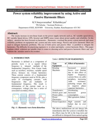
- 1. International Journal of Engineering and Techniques - Volume 3 Issue 2, March-April 2017 ISSN: 2395-1303 http://www.ijetjournal.org Page 103 Power system reliability improvement by using Active and Passive Harmonic filters K.V.Imayavaramban1 R.Karhikeyan2 1 PG Scholar , 2 Assistant Professor , Department of EEE, SCSVMV University, Enathur, Kancheepuram -631 561 I. INTRODUCTION Harmonics is defined as a component of periodic wave ( or a signal) whose frequency is integral multiple of the fundamental frequency. Non Linear loads such as rectifiers, inverters, variable speed drives, furnaces etc. Create harmonics These current consists of a fundamental frequency component rated at 50 Hz, plus a series of overlapping currents, with frequencies that are multiples of fundamental frequency. The result is deformation of the current (and, as a consequence, voltage) that has a series of associated secondary effects. Fig : 1 : Harmonic wave form distortion Table1: EFFECTS OF HARMONICS Type of Equipment Effect of harmonics Rotating Machines Increased power losses, over heating due to skin effect as higher frequency current flows on cable periphery, increasing cable resistance, pulsating torque due to negative phase sequence harmonics Transformers, Switch gears and Power cables Overheating, Increased power consumption Power Electronics Mal operation, failure, Power Capacitors High currents and failure due to over load The above malfunctions are not always felt immediately after the system is installed, but the effects may be felt in the long term and are difficult to distiguish from natural ageing RESEARCH ARTICLE OPEN ACCESS Abstract: The steady increase in non-linear loads on the power supply network such as, AC variable speed drives, DC variable Speed drives, UPS, Inverter and SMPS raises issues about power quality and reliability. In this subject, attention has been focused on harmonics . Harmonics overload the power system network and cause reliability problems on equipment and system and also waste energy. Passive and active harmonic filters are used to mitigate harmonic problems. The use of both active and passive filter is justified to mitigate the harmonics. The difficulty for practicing engineers is to select and deploy correct harmonic filters , This paper explains which solutions are suitable when it comes to choosing active and passive harmonic filters and also explains the mistakes need to be avoided.
- 2. International Journal of Engineering and Techniques - Volume 3 Issue 2, March-April 2017 ISSN: 2395-1303 http://www.ijetjournal.org Page 104 of equipment.Hence it is immprtant to some basic knowledge about harmonics and find solutions for the same II. HARMONICS AND POWER QUALITY The load influenced by harmonics on the power system network has increased drastically over the past few years. Harmonic currents are caused by non-linear loads. A non-linear load is a electricity consuming equipment that draws a non- sinusoidal current from the sinusoidal voltage power supply network. These harmonic currents flow in addition to the “active” sine wave current and generate additional losses in electrical installations, theses additional losses can result in thermal overload. Harmonic currents flow through the system impedance, and it causes voltage drops that will affect voltage quality. Sensitive loads, such as medical Equipments, IT equipments, Electronic equipments with communication port will have their operation affected if the voltage supply is distorted. Corrective Measures for reducing harmonics are implemented in order to resolve this issue and comply with national and international standards at every level of the power system network. In this article, we will discuss only on the use of passive and active harmonic filters in low- voltage installations III. TOPOLOGIES OF NON LINEAR LOAD In our further discussions we will be discussing on the six pulse rectifier bridge. The three-phase rectifier plays a key role. Major portion of the electrical energy is drawn from loads with this type of six pulse Rectifier Bridge. One general application that can be mentioned is the variable speed drive, VSD has been used for many years in every industrial application. The most general six-pulse rectifier topologies are shown in Figure 2. Topology A does not include any choke for smoothing the current. Topology B is operated using an upstream AC inductor Lac, usually in the form of a laminated line-reactor. Topology C has a built-in DC choke Ldc, which is often built in higher power motor drives. In all three topologies the grid, including the line impedance, is shown on the left-hand side. On the right the constant power sink “P=const” represents the active power drawn from the DC/AC inverter and motor that is considered, for example, to be 22 kW. (A) without Line Choke (B) with Line Choke Lac (C) : with DC Choke Ldc
- 3. International Journal of Engineering and Techniques - Volume 3 Issue 2, March-April 2017 ISSN: 2395-1303 http://www.ijetjournal.org Page 105 Figure 3 shows the input current i for topologies A, B and C from a balanced three-phase power line. Zline denotes the equivalent impedance of a distribution transformer, distribution line, fuses, etc., which are assumed to be half inductance and half resistive in our example (L=18uH; R=6mOhm). The following values are used: DC-link capacitor Cdc: 2000uF AC-reactor (topology B) Lac: 500uH (2%) DC-link choke (topology C) Ldc: 1mH Figure 3 shows the input current i for topologies A, B and C Figure 3: Input current i (white) and its active ia (green) and reactive ib (red) components for topologies A, B and C from Figure 3. All indicated values are in ARMS. The non-sinusoidal currents i (white waveforms in Figure 3), drawn from the sinusoidal voltage source, can be split into two orthogonal components, ia (active) and ib (reactive): a b i = i + i A B C Fig: 2 : Common Non Linear Load topologies with six pulse rectifier (A) Without choke (B) With Line Choke (C) with DC choke Ldc
- 4. International Journal of Engineering and Techniques - Volume 3 Issue 2, March-April 2017 ISSN: 2395-1303 http://www.ijetjournal.org Page 106 The active current ia (green), is a sinusoidal fundamental component in phase with the voltage. This is the only component of the current involved in transferring real power from the source to the load. The reactive current ib (red), is therefore the remaining component of the current, indicating the difference between the white and green curves. It only moves reactive power back and forth between the source and load, and is not at all involved in transferring real power. The reactive current spectrum consists of harmonics and reactive components of the fundamental frequency.. However, the reactive components of the fundamental in the waveforms in Figure 2 are negligible. The reactive current ib mainly consists of the 5th, 7th, 11th, 13th, 17th, 19th, 23rd and 25th harmonics, where higher-frequency harmonics (>25th harmonic) are also negligible. The reactive current generates additional losses in the power lines, and results in non-sinusoidal voltage drops across the line impedance, Reactive currents are mainly responsible for power line voltage distortions and thus for poor power quality. Consequently, it can be said that the reactive current is counterproductive. Hence reactive current should therefore be eliminated as far as possible. Figure 4: Harmonic spectrum of the line current i for topologies A, B, and C in Figure 3 . In addition to the harmonics (blue bars), the table represents the limits of standard EN61000-3-12 (white fields) and the actual THD values, as well as the individual harmonics (5th, 7th, 11th, 13th) and PWHD (partially weighted harmonic distortion). The values with red background indicate non-compliance with the standard, and the green background compliance with the standard. On the far right of each graph is a slider that can be used to select the Rsce parameter (Rsce=120 in our example Figure 4 Harmonic Spectrum of line Curent i for topologies A,B and C The RMS values of the currents i, ia, ib denoted as I, Ia , Ib are related according to the following formula: 2 2 2a b I = I + I It can be noted that the reactive current Ib will have a large variety of values, depending on the topology used. In our A B C
- 5. International Journal of Engineering and Techniques - Volume 3 Issue 2, March-April 2017 ISSN: 2395-1303 http://www.ijetjournal.org Page 107 example the RMS current values are 45.5 A, 17.4 A and 13.9 A (Figure 2). The reactive current has a considerable influence on the input current I. In this example the RMS value of the line current varies according to the topology (for the same output power) from 53.4 A to 31.1 A. Only the active current Ia remains more or less equal in all three topologies (28.0 A and. 27.8 A respectively). The understanding that can be drawn from the above reading is that the RMS value for the active current Ia (which is proportional to the real power absorbed from the voltage source) can, in the case of non-linear loads such as six-pulse rectifiers, be significantly lower than the value of the input current I. In other words, it is not possible to determine the active current Ia if only the value of the input current I is known. The most direct way to get Ia is to calculate it from the real power absorbed from the power line P: real power drawn from the three-phase power line Up-n: RMS value of the phase-neutral voltage The value for the real power P can be calculated from: PM: real power absorbed by the motor η: efficiency of the motor drive (typically 0.96) THE IDEAL HARMONIC FILTER The ideal harmonic filter can be seen as a equipment that is capable of completely removing reactive current ib by removing harmonics and correcting the phase of the fundamental current. As a result, this kind of filter converts the non-sinusoidal line current into a sinusoidal current, and thus the non-linear load into a linear load that only draws useful active current ia. If we provide the loss-free operation of the filter, the real power drawn from the power line will not be changed by the presence of the filter and thus the active current ia will not be increased. Figure 5: six-pulse rectifiers arranged in topologies A, B and C with the passive harmonic filter connected on the line side. Note: Passive harmonic filters must be connected directly at the input of a non- linear load (or group of non-linear loads). Due to the voltage distortion at the filter output, which occurs as a result of the non sinusoidal voltage drop across the series impedance, it is not appropriate to supply power to other loads at the filter output. PHF PHF PHF
- 6. International Journal of Engineering and Techniques - Volume 3 Issue 2, March-April 2017 ISSN: 2395-1303 http://www.ijetjournal.org Page 108 Figure 6 illustrates the shape of the waveform for the input current of one phase when passive harmonic filters are used, in the case of all three rectifier topologies. Figure 6: The line current i (white) and its active ia (green) and reactive ib (red) components for topologies A, B and C with an passive harmonic filter installed at the input. IMPORTANT OBSERVATIONS If passive series harmonic filters, are used at the input of the six-pulse rectifier, the following important observations can be made: Reactive current ib (red) is not visible in the waveforms (Figure 6). Table 2: Reactive current comparison Topology Reactive Current (Ib) with out Passive Filter Reactive Current (Ib) with Passive Filter A 45.5 Arms 1.1 Arms B 17.4 Arms 1.2 Arms C 13.9Arms 1.2 Arms The RMS value of the line current i (white) are reduced; the line current’s shape is almost sinusoidal (free from harmonics). Table 3: Line Current comparison Topology Line Current (i) with out Passive Filter Line Current (i) with Passive Filter A 53.4 Arms 28.3 Arms B 32.8 Arms 28.3 Arms C 31.1 Arms 28.3 Arms The active current ia (green) has remained practically unchanged. Table 4: Active Current comparison Topology Active Active A B C
- 7. International Journal of Engineering and Techniques - Volume 3 Issue 2, March-April 2017 ISSN: 2395-1303 http://www.ijetjournal.org Page 109 Current (ia) with out Passive Filter Current (ia) with Passive Filter A 28.0 Arms 28.3 Arms B 27.8 Arms 28.3 Arms C 27.8 Arms 28.3 Arms Note: The increase in active current is a result of the fact that a harmonic filter will never be ideal, but always there is slight loss. However, due to the minimal power losses due to passive filter is negligible. CORRECT SELECTION OF PASSIVE HARMONIC FILTERS The conclusions obtained above clarify that where the problem lies: the proper rating of a harmonic filter must be concluded from the ratings of a non-linear load without a harmonic filter. The comparison between the following two tables makes it clear that the line current of the non-linear load is not suitable for selecting a harmonic filter, such as any make passive filter, as it changes according to the topology Table 5: Rating of non-linear load (topologies A, B, C) without harmonic filters. Rectifier A(Without magnetic) A rms B (with Lac) A rms C ( with Ldc) A rms Line Current (I) 52.4 32.8 31.1 Active Current (Ia) 28 27.8 27.8 Reactive current( Ib) 45.5 17.4 13.9 Active 20 20 20 real power (KW) Table 6: Rating of the passive harmonic filters for topologies A, B and C. Rectifier A(Without magnetic) A rms B (with Lac) A rms C ( with Ldc) A rms Line Current (I) 28.3 28.3 28.3 Active Current (Ia) 28.3 28.3 28.3 Reactive current( Ib) 1.1 1.2 1.2 Active real power (KW) 20 20 20 In fact, only the active current Ia and real power P are identical for all three topologies, thus making them suitable for sizing the filter. Unfortunately, the active current Ia (which is actually the harmonic filter’s input rated current) is generally not known based on the specifications of non- linear loads (e.g. motor drives). The only indicative value that is suitable without any restrictions for sizing the passive harmonic filter is therefore the real power P of the non-linear load. To simplify the filter selection for the user The Passive harmonic filters based on the motor drive’s power rating and not on the input current.
- 8. International Journal of Engineering and Techniques - Volume 3 Issue 2, March-April 2017 ISSN: 2395-1303 http://www.ijetjournal.org Page 110 CORRECT SELECTION OF ACTIVE HARMONIC FILTERS Unlike passive harmonic filters, active filters are installed in parallel to the power line (shunt filters). Note that only topologies B and C are represented in figure 7. Topology A is not advisable because active shunt filters require magnetic components on the load for economic reasons. This is obvious from another look at the waveforms in Figure 2. If there were no magnetic components (topology A) the required corrective current of the active filter would be so high that the filter would need to be significantly oversized. Figure 7: six-pulse rectifiers for topologies B and C with an active harmonic filter connected in parallel(shunt filter). If, for simplicity’s sake, an ideal shunt filter is considered based on topologies B and C in Figure 7, it is not difficult to realize that the line current corresponds to the active current ia in Figure 3 (B and C), the filter’s corrective current corresponds to the reactive current ib in Figure3 (B and C), the rectifier’s input current corresponds to the input current i in Figure 3 (B and C). These statements are true, provided that the line impedance Zline is negligible in relation to the impedances of Lac (topology B) and Ldc (topology C). In our example this condition is fully met. When selecting active harmonic filters, a similar issue needs to be addressed as when choosing the passive versions. One must calculate the filter rating based on the rectifier parameters without a filter. Table 3 lists key parameters for topologies B and C (without a filter). The only value that is really of any use is the reactive current Ib, which describes the active filter’s most important parameter: the corrective current required Table 7: Rating the active harmonic filter for topologies B and C. The values in red are usually not available from the load specifications. Rectifier B with Lac B with Ldc Line Current ( I) 32.8 31.1 Active current Ia 27.8 27.8 Reactive current (Ib) 17.4 13.9 Active real power KW 20 20 Unlike in the case of passive harmonic filters, there is a difference when it comes to dimensioning active harmonic filters for topologies B and C. The required corrective current for topology B is 17.4 Arms, whereas it is only 13.9 Arms for topology C. To give the complete picture, it should also be mentioned at this point that the corrective current required without any choke (topology A) would be 45.5 Arms. Unfortunately, the value for the
- 9. International Journal of Engineering and Techniques - Volume 3 Issue 2, March-April 2017 ISSN: 2395-1303 http://www.ijetjournal.org Page 111 reactive current Ib is usually not available from the specification of the non-linear load. The simplest way to find this value of Ib would be to calculate it from the following formula: I: rms of the line current of the non-linear load without a harmonic filter P: real power of the load Up-n: phase-neutral voltage of the power line All these values can usually be found in the specification of the non-linear load. The calculated results tally exactly with the values from Figure 2 which were calculated using FFT (Fourier Transformation) CONCLUSION Proper selection of passive and active harmonic filters is really difficult task for practicing engineers due to complexity in understanding the cause and effects of harmonics and due to misunderstandings of many number of unknown parameters of the non-linear load. But selecting the correct size of filter is key task to achieve the optimum cost/benefit ratio, i.e. the desired reduction in current harmonics with minimal filtering effort. Given that some motor drive peripherals such as EMI filters, line-reactors or output filters are designed and selected based on the line current I, it is often wrongly assumed that this is also appropriate for harmonic filters. The correct and best procedure however is to select passive harmonic filters based on the load’s real power P, and to select active harmonic filters based on the calculated reactive current Ib. Hence by selecting the correct solution and selection Passive and Active Harmonic filters, power system reliability will be improved from the ill effects of harmonics in the power system infrastructure. REFERENCES 1. Fryze, S. (1932) Wirk-, Blind- und Scheinleistung in elektrischen Stromkreisen mit nichtsinusförmigem Verlauf von Strom und Spannung, Elektrotechnische Zeitschrift, June, 596-9. 2. A. Pietkiewicz, Virtual Laboratory for Harmonics Filtering Visualization, Proceedings of IEEE International Symposium on Power Electronics, Electrical Drives, Automation and Motion,(SPEEDAM 2008), Ischia, Italy, p.508 512. 3. IEC 61000-3-12: Electromagnetic compatibility (EMC) – Part 3-12: Limits for harmonics currentproduced by equipment connected to public low-voltage systems with input current >16A and <75A per phase. IEC, Aug. 2004. 4. Engineering Recommendation G5/4-1 Planning levels for harmonic voltage distortion and the connection of nonlinear equipment to transmission systems and distribution networks in the United Kingdom. Energy Network Association, Oct. 2005. 5. IEEE Recommended Practices and Requirements for Harmonic Control in Electrical Power Systems. IEEE Std 519- 1992